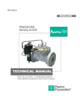
PRESSURE REGULATOR
DIXI
TECHNICAL MANUAL MT035
INSTALLATION, COMMISSIONING AND MAINTENANCE ISTRUCTIONS
E

2
TECHNICAL MANUAL MT035
DIXI
INLET PRESSURE
PILOT FEED
OUTLET PRESSURE
MOTORIZATION
Issue November 2002

TECHNICAL MANUAL MT035
3
The PIETRO FIORENTINI SPA with registered office in Milan (Italy) – via Rosellini, 1, declares under its sole
responsibility that the apparatus series Dixi bearing the CE marking showed in this manual are designed,
manufactured, tested and inspected in accordance with the provisions of Pressure Equipment Directive 97/23/EC
(PED).
Following conformity assessment procedure has been carried out:
➤EC type-examination (module B) by DVGW (ID n°0085) – report 02/232/4301/855 issued 09rd July 2002.
In this report all versions are classified as safety accessories according to clause 2.1.3 of art. 1 of PED.
➤Production quality assurance (module D) by BUREAU VERITAS (ID n°0062) – Attestation d’Approbation
du Système Qualité N°CE-PED-D-FIO001-02-ITA issued 15th May 2002.
Further it declares that the classification of the performances characteristics has been verified by DVGW
according to the procedures given by European standard EN 334 and/or by standard DIN 3381. The classification is
detailed in the aforesaid DVGW report.
Arcugnano 25/9/2002 The Pietro Fiorentini SpA
DECLARATION OF CONFORMITY

4

TECHNICAL MANUAL MT035
5
GENERAL PRECAUTIONS
- The apparatus described in this manual is a device subject to pressure installed in systems under pressure;
- the apparatus in question is normally installed in systems for transporting flammable gases (natural gas, for
example).
PRECAUTIONS FOR THE OPERATORS
Before proceeding with installation, commissioning or maintenance, operators must:
- examine the safety provisions applicable to the installation in which they must work;
- obtain the authorisations necessary for working when so required;
- use the necessary means of individual protection (helmet, goggles, etc.);
- ensure that the area in which they operate is fitted with the means of collective protection envisaged and with
the necessary safety indications.
HANDLING
The handling of the apparatus and of its components must only be carried out after ensuring that the lifting gear
is adequate for the loads to lift (lifting capacity and functionality). The apparatus must be handled using the lifting
points provided on the apparatus itself.
Motorised means must only be used by the persons in charge of them.
PACKING
The packing for trasportation of equipment and of relevant spare parts are designed and shaped to avoid damage to any
part during transportation, warehousing and handling activities. Therefore the equipment and spare parts shall be kept
into their packing until their installation in the final site. After packing is open, check that no damage occured to any
goods. If damage occured inform the supplier and keep packing for any verification.
INSTALLATION
If the installation of the apparatus requires the application of compression fittings in the field, these must be
installed following the instructions of the manufacturer of the fittings themselves. The choice of the fitting must
be compatible with the use specified for the apparatus and with the specifications of the system when envisaged.
PRECAUTIONS

TECHNICAL MANUAL MT035
COMMISSIONING
Commissioning must be carried out by adequately trained personnel.
During the commissioning activities, the personnel not strictly necessary must be ordered away and the no-go
area must be properly signalled (signs, barriers, etc.).
Check that the settings of the apparatus are those requested; if necessary, reset them to the required values in
accordance with the procedures indicated in the manual.
When commissioning, the risks associated with any discharges into the atmosphere of flammable or noxious
gases must be assessed.
In installations in natural gas distribution networks, the risk of the formation of explosive mixtures (gas/air) inside
the piping must be considered.
CONFORMITY TO DIRECTIVE 97/23/EC (PED)
Pressure regulator Dixi is classified as fail close regulator according to the standard EN 334 therefore it is
categorized as safety accessory according to directive 97/23/EC (PED).
The regulator Dixi when incorporating slam shut valve LA/... with pressure switches for overpressure is
categorized as safety accessory according to PED, therefore it can be used both as pressure accessory and safety
accessory to PED.
Conformity with Directive 97/23/EC of pressure regulator and relevant accessory bearing the CE marking require
installation in the system with minimum requirements according to EN 12286.
6

7
TECHNICAL MANUAL MT035
1.0 INTRODUCTION. . . . . . . . . . . . . . . . . . . . . . . . . . . . . . . . . . . . . . . . . . . . . . . . . . . . . . . . . . . PAGE 9
1.1 MAIN SPECIFICATIONS . . . . . . . . . . . . . . . . . . . . . . . . . . . . . . . . . . . . . . . . . . . . . . . . . . . . . . . . . . . . . . . . . . . 9
1.2 OPERATION . . . . . . . . . . . . . . . . . . . . . . . . . . . . . . . . . . . . . . . . . . . . . . . . . . . . . . . . . . . . . . . . . . . . . . . . . . . . 9
1.3 SETTING SPRINGS . . . . . . . . . . . . . . . . . . . . . . . . . . . . . . . . . . . . . . . . . . . . . . . . . . . . . . . . . . . . . . . . . . . . . 11
2.0 INSTALLATION. . . . . . . . . . . . . . . . . . . . . . . . . . . . . . . . . . . . . . . . . . . . . . . . . . . . . . . . . . . . . . . 12
2.1 GENERAL . . . . . . . . . . . . . . . . . . . . . . . . . . . . . . . . . . . . . . . . . . . . . . . . . . . . . . . . . . . . . . . . . . . . . . . . . . . . 12
3.0 ACCESSORIES . . . . . . . . . . . . . . . . . . . . . . . . . . . . . . . . . . . . . . . . . . . . . . . . . . . . . . . . . . . . . . . 14
3.1 RELIEF VALVE . . . . . . . . . . . . . . . . . . . . . . . . . . . . . . . . . . . . . . . . . . . . . . . . . . . . . . . . . . . . . . . . . . . . . . . . . 14
3.1.1 DIRECT INSTALLATION IN THE LINE . . . . . . . . . . . . . . . . . . . . . . . . . . . . . . . . . . . . . . . . . . . . . . . . . . . . . . . . 15
3.1.2 INSTALLATION WITH ON/OFF VALVE . . . . . . . . . . . . . . . . . . . . . . . . . . . . . . . . . . . . . . . . . . . . . . . . . . . . . . . . 16
4.0 MODULARITY . . . . . . . . . . . . . . . . . . . . . . . . . . . . . . . . . . . . . . . . . . . . . . . . . . . . . . . . . . . . . . . 17
4.1 LA/... INCORPORATED SLAM-SHUT . . . . . . . . . . . . . . . . . . . . . . . . . . . . . . . . . . . . . . . . . . . . . . . . . . . . . . . . . 17
4.1.1 LA/... SLAM-SHUT SETTING SPRINGS . . . . . . . . . . . . . . . . . . . . . . . . . . . . . . . . . . . . . . . . . . . . . . . . . . . . . . . 19
4.2 MONITOR . . . . . . . . . . . . . . . . . . . . . . . . . . . . . . . . . . . . . . . . . . . . . . . . . . . . . . . . . . . . . . . . . . . . . . . . . . . . 20
4.2.1 IN-LINE MONITOR . . . . . . . . . . . . . . . . . . . . . . . . . . . . . . . . . . . . . . . . . . . . . . . . . . . . . . . . . . . . . . . . . . . . . . 21
5.0 START UP. . . . . . . . . . . . . . . . . . . . . . . . . . . . . . . . . . . . . . . . . . . . . . . . . . . . . . . . . . . . . . . . . . 22
5.1 GENERAL . . . . . . . . . . . . . . . . . . . . . . . . . . . . . . . . . . . . . . . . . . . . . . . . . . . . . . . . . . . . . . . . . . . . . . . . . . . . 22
5.2 GAS INPUT, CONTROL OF EXTERNAL TIGHTNESS AND SETTING. . . . . . . . . . . . . . . . . . . . . . . . . . . . . . . . . . . 23
5.3 COMMISSIONING THE REGULATOR. . . . . . . . . . . . . . . . . . . . . . . . . . . . . . . . . . . . . . . . . . . . . . . . . . . . . . . . . 24
5.4 COMMISSIONING THE REGULATOR WITH INCORPORATED SLAM-SHUT VALVE . . . . . . . . . . . . . . . . . . . . . . 25
5.5 COMMISSIONING THE REGULATOR PLUS DIXI IN-LINE MONITOR WITH INCORPORATED SLAM-SHUT. . . . . . 29
6.0 TROUBLE-SHOOTING . . . . . . . . . . . . . . . . . . . . . . . . . . . . . . . . . . . . . . . . . . . . . . . . . . . . . . . . . . 32
6.1 DIXI REGULATOR . . . . . . . . . . . . . . . . . . . . . . . . . . . . . . . . . . . . . . . . . . . . . . . . . . . . . . . . . . . . . . . . . . . . . . 32
6.2 LA/... SLAM-SHUT . . . . . . . . . . . . . . . . . . . . . . . . . . . . . . . . . . . . . . . . . . . . . . . . . . . . . . . . . . . . . . . . . . . . . 33
7.0 MAINTENANCE . . . . . . . . . . . . . . . . . . . . . . . . . . . . . . . . . . . . . . . . . . . . . . . . . . . . . . . . . . . . . . 34
7.1 GENERAL . . . . . . . . . . . . . . . . . . . . . . . . . . . . . . . . . . . . . . . . . . . . . . . . . . . . . . . . . . . . . . . . . . . . . . . . . . . . 34
7.2 PROCEDURE FOR DISASSEMBLING COMPLETELY CHANGING THE SPARE PARTS, AND REASSEMBLING . . . . . .
OF DIXI PRESSURE REGULATOR WITH P90 + RR40 PILOT . . . . . . . . . . . . . . . . . . . . . . . . . . . . . . . . . . . . . . . 35
8.0 FINAL OPERATION . . . . . . . . . . . . . . . . . . . . . . . . . . . . . . . . . . . . . . . . . . . . . . . . . . . . . . . . . . . . 41
8.1 TIGHTNESS AND SETTINGS CONTROL . . . . . . . . . . . . . . . . . . . . . . . . . . . . . . . . . . . . . . . . . . . . . . . . . . . . . . 41
8.2 START UP . . . . . . . . . . . . . . . . . . . . . . . . . . . . . . . . . . . . . . . . . . . . . . . . . . . . . . . . . . . . . . . . . . . . . . . . . . . . 41
9.0 LIST OF RECOMMENDED SPARE PARTS . . . . . . . . . . . . . . . . . . . . . . . . . . . . . . . . . . . . . . . . . . . . . . 43
INDEX

8

TECHNICAL MANUAL MT035
The scope of this manual is to provide the essential information for the installation, commissioning, disassembly,
reassembly and maintenance of Dixi regulators.
A brief illustration of the main features of the regulator and its accessories ia also provided.
1.1 MAIN SPECIFICATIONS
The DIXI pressure regulator is a regulator of the piloted type for medium and high pressures.
The Dixi is a fail close type regulator and therefore closed in the event of:
•rupture of the main diaphragm;
•rupture of the pilot diaphragm/s;
•pilot circuit supply failure.
It permits the down-line pressure to be maintained constant with variations in the up-line pressure or the
requested flow.
The main features of this regulator are:
• use of non-corrosive gases, previously filtered;
• design pressure: 16 bar;
•design temperature: -10 °C to +50 °C;
• ambient temperature: -20°C to +60 °C;
•inlet pressure range bpe: 0.5 to 16 bar;
•possible regulation range Wh: 0.02 to 6 bar (depending on the pilot installed);
•minimum pressure differential: 0.5 bar;
•class of accuracy RG: up to 5;
•closing pressure class SG: up to 20.
1.2 OPERATION (FIG. 1)
If there is no pressure, the obturator 3 is maintained in the closed position by the spring 43 and rests on the valve
seat 2. The upstream pressure, even if variable, does not modify this position as the obturator, because of the hole
A, finds itself between two equal pressures acting on equal surface areas. The rod 9 is also between two equal
pressures as the upstream pressure is also brought to the chamber C through the hole A.
The obturator is controlled by the diaphragm 15 on which the following forces are exerted:
•downwards: the load of the spring 43, the thrust deriving from the regulated pressure Pa in the chamber D and
the weight of the mobile assembly;
•upwards: the thrust from the motorization pressure Pm in the chamber E, supplied by the pilot.
The motorization pressure is obtained by taking gas from the regulator at the upstream pressure.
9
1.0 INTRODUCTION

TECHNICAL MANUAL MT035
10
Fig. 1
Connections to be made by the customer
Ref. No. for the connections
Internal regulator
connections
P90 + RR40
The gas is filtered through filter 28 and undergoes an initial decompression in the adjustable pre-regulator RR40
(fig. 2), composed essentially of an obturator 31, a spring 40 and a diaphragm 25, to a value Pep which depends
on the setting of the regulator.
Fig. 2
P90 + RR40 Pilot
P9…Regulation ring
RR40 Regulation ring

TECHNICAL MANUAL MT035
11
The adjustment of Pep is made by turning the ring 10 (clockwise to increase it and anticlockwise to reduce it), and
its value can be read on the pressure gauge installed directly on the body of the pre-regulator. From the chamber
G the pressure Pep then passes through the hole F in the incorporated pilot P9.. which regulates it by means of
the obturator 17 up to the regulator head inlet value Pm.
The regulation of Pm is obtained by means of the contrast between the force exerted by the setting spring 71 of
the pilot and by the action of the regulated pressure Pa acting in the chamber B on the diaphragm 23. The setting
is modified by turning the setting ring 11; the pressure Pm, and therefore the regulated pressure Pa are increased
by turning clockwise; vice-versa by turning anticlockwise.
If during operation, for example, there is a drop in the downstream pressure Pa (because of an increase in the flow
rate demand, or a drop in the upstream pressure) there is an imbalance in the mobile assembly 16 of the pilot
which moves and increases the opening of the obturator 17. As a result, the value of the motorization pressure
Pm also increases and, acting on the chamber E below the diaphragm 15 (fig. 1) causes the obturator 3 to move
upwards and therefore an increase in the opening of the regulator until the regulated pressure set point is restored.
Vice-versa, when the regulated pressure begins to increase, the force exerted on the diaphragm 23 shifts the
mobile assembly 16 and moves the obturator 17 towards the closed position. The pressure Pm then drops, due
to the transfer between chambers E and D through orifice 30, and the force exerted by spring 43 causes the
obturator 3 to move downwards, thereby returning the regulated pressure to the set point.
In normal working conditions, the obturator 17 positions itself so that the value of the motorization pressure Pm
is such as to maintain the downstream pressure Pa around the preset value.
The Dixi regulator uses the P90, P92 and P94 pilots with the RR40 pre-regulator incorporated.
Tables 1 and 2 show the fields of regulation of the pre-regulator and of the various pilots.
Tab. 1 RR40 Pre-regulator setting springs
Code Colour De Lo d i it Setting range in bar
1 2700338 WHITE 1,3 8,75 10,75 0,11 ÷0,22
2 2700375 YELLOW 40 1,5 5,25 6,75 0,22 ÷0,58
3 2700464 ORANGE 15 1,7 8,5 10,5 0,5 ÷0,86
4 2700510 RED 2 5,25 7,25 0,85 ÷2
5 2700745 GREEN 35 2,5 5,25 7,25 1,95 ÷4,7
6 2700980 BLACK 3 6 8 4,6 ÷8,2
1.3 SETTING SPRINGS
N.B.: Recommended set-point: Pep= Pa + (0.15 ÷ 0.2) bar
Tab. 2 Pilots P90-92-94 setting springs
PILOT P90
Code Colour De Lo d i it Setting range in mbar
1 2700400 WHITE 1,5 7 9 6 ÷15
2 2700545 YELLOW 25 55 2 7,5 9,5 14 ÷50
3 2700790 ORANGE 2,5 8 10 49 ÷120
4 2701010 RED 3 7 9 110 ÷270
PILOT P92
1 2701010 RED 25 55 3 7 9 260 ÷660
2 2701225 GREEN 3,5 6 8 650 ÷1110
PILOT P94
1 2701010 RED 3 7 9 1000 ÷2100
2 2701225 GREEN 25 55 3,5 6 8 2000 ÷5000
3 2701475 BLACK 4 6 8 4900 ÷6000
De = Ø external diameter d = Ø wire diameter i= active coils Lo = Lenght it = total coils

MANUALE TECNICO MT49
12
Fig. 3 (Standard regulator)
2.1 GENERAL
Pressure regulator does not require any supplementary upstream safety accessory for protection against
overpressure compared with its design pressure PS, when upstream reducing station is sized for a max
downstream incidental pressure MIPd ≤1,1 PS.
Before installing the regulator it is necessary to ensure that:
- the regulator can be inserted in the space provided and that subsequent maintenance operations will be
sufficiently practicable;
- the upstream and downstream piping is at the same level and capable of supporting the weight of the regulator;
- the inlet/outlet flanges of the piping are parallel;
- the inlet/outlet flanges of the regulator are clean and the regulator itself has not been subject to damage during
transport;
- the piping upstream has been cleaned to expel residual impurities such as welding scale, sand, paint residues,
water, etc.
The normally raccomended set-up is:
2.0 INSTALLATION

TECHNICAL MANUAL MT035
13
Regulator
Outlet connection
Sensing line Control pressure gauge
Bleed cock
On/Off valve
Tab. 3 CONNECTING THE APPARATUSES
The connections between the apparatus and the main piping must be made using stainless steel or copper pipe
with minimum internal diameter of 8 mm.
IN-LINE INSTALLATION
INSTALLATION AT RIGHT ANGLES
Regulator
Outlet connection
Sensing line
Control pressure gauge
Bleed cock
On/Off valve

TECHNICAL MANUAL MT035
14
1 and 2Connect to regulators heads
3 and 4Connect to pilots
5 and 6Connect accelerator and slam-shut
The regulator must be installed in the line with the arrow on the body pointing in the gas flow direction.
It is indispensable for good regulation for the position of the downstream pressure take-offs and the speed of the
gas at the take-off point to respect the values given in tables 3 and 4 (positioning) and 5 (speed).
The pressure regulator, when installed on a reducing station, shall be installed at least according to the
requirements of standard EN 12186.
All venting connections shall be connected as required by above mentioned standard.
The following is recommended so as to prevent the accumulation of impurities and condensate in the lines of the
pressure take-offs:
a) the lines themselves must slope down towards the downstream piping with a slope of about 5-10%;
b) the connectors on the piping must always be welded on the top of the piping itself and there must be no burr
or inward protrusions in the hole in the piping.
NB. WE RECOMMEND NOT TO PUT ON/OFF VALVES ON THE IMPULSE TAKE-OFFS.
Tab. 4 DETAIL OF MULTIPLE TAKE - OFF WITH OF THE IMPULSE TAKE - OFF REFERENCE NUMBERS
Tab. 5
The speed of the gas must not exceed the following values in the piping downstream from the regulator:
Vmax= 30 m/s for Pa > 5 bar
Vmax= 25 m/s for 0,5 < Pa < 5 bar
Vmax= 15 m/s for Pa < 0,5 bar
3.0 ACCESSORIES
3.1 RELIEF VALVE
The relief valve is a safety device which releases a certain quantity of gas to the exterior when the pressure at the
control point exceeds the set-point as a result of shortlasting events such as, for example, the very fast closing of
the on/off valves and/or overheating of the gas with zero flow rate demand. The release of the gas to the exterior
can, for example, delay or block the intervention of the slam-shut valve for transitory reasons deriving from dama-
ge to the regulator.

TECHNICAL MANUAL MT035
15
Obviously the quantity of gas released depends on the extent of the overpressure with respect to the set-point. The
different models of relief valves available are all based on the same operating principle which is illustrated below
with reference to the valve VS/AM 55 (fig. 4).
It is based on the contrast between the thrust on the diaphragm 24 deriving from the pressure of the gas to control
and the thrust from the setting spring 20. The weight of the mobile assembly, the static thrust and the residual
dynamic thrust on the obturator 4 also contribute to this contrast.
When the thrust deriving from the pressure of the gas exceeds that of the setting spring, the obturator 4 is raised
and a certain quantity of gas is released as a result.
As soon as the pressure drops below the set-point, the obturator returns to the closed position. Proceed as
indicated below to control and adjust intervention of the relief valve.
3.1.1 DIRECT INSTALLATION IN THE LINE (FIG. 5)
When the relief valve is fitted directly in the line, that is without inserting an on/off valve, proceed as follows:
1)Ensure that the downstream on/off valve V2 and the bleed cock 6 are closed;
2)Increase the pressure in the downstream section up to the value envisaged for intervention in one of the
following ways:
- if the spring fitted on the pilot permits it (see tables 1-2), increase the setting of the pilot itself until the
desired value is obtained;
- connect a controlled auxiliary pressure to the cock 6 and stabilize it at the desired value;
3)Check the intervention of the relief valve and adjust it necessary by turning the internal adjustment ring 14
appropriately (clockwise to increase and anticlockwise to decrease).
Fig. 5
Fig. 4

TECHNICAL MANUAL MT035
16
3.1.2 INSTALLATION WITH ON/OFF VALVE (FIG. 6)
1) Close the on-off valve 16.
2) Connect a controlled auxiliary pressure to the nipple 17 and increase it slowly up to the value envisaged for
intervention.
3) Check the intervention of the relief valve and adjust it necessary by turning the internal adjustment ring 14
appropriately (clockwise to increase and anticlockwise to decrease).
Fig. 6

TECHNICAL MANUAL MT035
17
4.0 MODULARITY
The modular-type conception of DIXI series regulators means that it is also possible to fit the slam-shut
incorporated with the body itself even after the installation of the regulator.
Furthermore, the regulator can be adapted for operation as with in-line monitor by istalling a special device.
4.1 LA/... INCORPORATED SLAM-SHUT
This is a device (fig. 7-8) which immediately blocks the gas flow if, because of some failure, the downstream
pressure reaches the point set for its intervention, or if it is actuated manually.
With the Dixi pressure regulator, the slam-shut can be incorporated on both the service regulator or on the in-line
monitor. Three versions (LA/BP, LA/MP and LA/TR) are available depending on the intervention pressure ranges.
The main features of the slam-shut device are as follows:
•cover design pressure: 16 bar;
•intervention for pressure increase and/or decrease;
•accuracy AG: ± 5% of the set point for pressure increases; ± 15% of the set point for pressure drops;
•internal by-pass device;
•manual button-operated actuating device.
Fig. 7

TECHNICAL MANUAL MT035
18
The slam-shut valve LA/.. consists essentially of an obturator (fig. 8) fitted on a rod, a releasing lever system, a
control head and a manual resetting system.
The pressure to control Pa, in chamber C of the control head, acts on the diaphragm 28 which is integral with the
cam shaft 16.
The load of the pressure Pa on the diaphragm is countered by the springs 34 and 35 which respectively determine
intervention for pressure increase or decrease.
The device is set by turning the rings 17 and 18. Turning the rings clockwise increases the intervention value;
turning anticlockwise decreases it.
Intervention as a result of a pressure increase occurs as follows: when the pressure Pa exceeds the setting valve,
the load on the diaphragm 28 increases until it overcomes the resistance of the spring 34. This causes the shaft
to translate towards the left so that the cam shifts the feeler 33. In this way, the rod 5 with the obturator 19 is freed
and closed by the spring 8.
On the other hand, intervention as a result of a pres-sure decrease occurs as follows: as long as the pressure Pa
stays above the load of the spring 35, the spring support rests on the support 12. If the pressure Pa drops below
the setting, the spring 35 translates the support to the right and with it the shaft. The cam shifts the feeler 33 and
trips the lever mechanism 29.
The slam-shut is reset by unscrewing the threaded bushing 7 and pulling it downwards until the lever mechanism
29 is reset. During the first phase of the operation, it will be necessary to wait until the upstreamupstream
pressure, through the internal by-pass, passes downstream from the obturator to rebalance it. After resetting, the
bushing 7 must be screwed back to its seat It is possible to see from the outside whether the slam-shut is open
or closed by observing the position of the nut 37 through the aperture in the bushing 7, as shown in figure 8.
Table 6 shows the field of intervention for the pressure switches available.
LA/BP Slam-shut
Fig. 8
C
Detail of manual button
operated actuating device
Note: the O-ring 25 is used for particular
versions

TECHNICAL MANUAL MT035
19
De = Ø external diameter d = Ø wire diameter i= active coils Lo = Length it = total coils
4.1.1 Tab.6 LA/... SLAM-SHUT SETTING SPRINGS
Springs characteristics LA/BP/MP SLAM-SHUT
Code Colour De Lo d i it SETTING RANGE in mbar
Intervention for max pressure
1 2700632 WHITE 34 43 2,2 5,5 7,5 30 ÷60
2 2700912 YELLOW 46 2,8 5 7 60 ÷180
Intervention for min pressure
4 2700327 WHITE 15 45 1,3 6,5 8,5 6 ÷60
Intervention for max pressure
5 2701143 ORANGE 34 40 3,2 4,5 6,5 180 ÷280
6 2701139 RED 50 3,2 4,5 6,5 280 ÷450
Intervention for min pressure
7 2700514 YELLOW 15 40 2 6,75 8,75 60 ÷240
LA/TR SLAM-SHUT
Intervention for max pressure
11 2701143 ORANGE 40 3,2 4,5 6,5 250 ÷550
12 2701139 RED 50 3,2 4,5 6,5 550 ÷850
13 2701246 BLACK 34 50 3,5 5 7 850 ÷1500
14 2701522 BLUE 50 4 4 6 1500 ÷2500
15 2701775 VIOLET 50 4,5 4,5 6,5 2500 ÷4000
16 2702064 SKY-BLUE 50 5 4 6 4000 ÷5500
IIntervention for min pressure
17 2700514 YELLOW 40 2 6,75 8,75 100 ÷600
18 2700989 ORANGE 15 40 3 6,5 8,5 600 ÷2000
19 2701185 RED 43 3,2 7,5 9,5 2000 ÷3500

TECHNICAL MANUAL MT035
20
4.2 MONITOR
The monitor is an emergency regulator which comes into operation to replace the service regulator if, for any
reason, the latter permits the downstream pressure to rise up to the value set for its intervention.
The in-line monitor solution is available on the Dixi regulator (fig. 10). In this configuration, the monitor regulator
is identical in every way to a standard regulator while there is a constructive variant in the service regulator, as
illustrated in fig. 9.
This variant is necessary because the pressure which feeds the service regulator pilot is taken off upstream from
the monitor from its intermediate flange, and then brought by an external connection to the intermediate flange of
the service regulator. This pressure must therefore be isolated from the pressure which arrives from the zone
upstream from the service regulator itself through the hole in the rod.
Fig. 9
Standard regulator Variant to service regulator in applications with monitor
Page is loading ...
Page is loading ...
Page is loading ...
Page is loading ...
Page is loading ...
Page is loading ...
Page is loading ...
Page is loading ...
Page is loading ...
Page is loading ...
Page is loading ...
Page is loading ...
Page is loading ...
Page is loading ...
Page is loading ...
Page is loading ...
Page is loading ...
Page is loading ...
Page is loading ...
Page is loading ...
Page is loading ...
Page is loading ...
Page is loading ...
Page is loading ...
Page is loading ...
Page is loading ...
Page is loading ...
Page is loading ...
Page is loading ...
Page is loading ...
Page is loading ...
Page is loading ...
/
