Page is loading ...

AVR250
HANDBOOK
Arcam AVR250 surround sound receiver
English
Français
Deutsch
Nederland
s

AVR250
E-2
AVR250
E-3
English
RISQUE DE CHOC ELECTRIQUE
NE PAS OUVRIR
ATTENTION
CAUTION
RISK OF ELECTRIC
SHOCK DO NOT OPEN
CAUTION: To reduce the risk of electric shock, do not remove cover (or back). No user serviceable parts
inside. Refer servicing to qualied service personnel.
WARNING: To reduce the risk of re or electric shock, do not expose this apparatus to rain or moisture.
The lightning ash with an arrowhead symbol within an equilateral triangle, is intended to alert the user to the presence
of uninsulated ‘dangerous voltage’ within the product’s enclosure that may be of sufcient magnitude to constitute a risk
of electric shock to persons.
The exclamation point within an equilateral triangle is intended to alert the user to the presence of important operating
and maintenance (servicing) instructions in the literature accompanying the product.
CAUTION: In Canada and the USA, to prevent electric shock, match the wide blade of the plug to the wide
slot in the socket and insert the plug fully into the socket.
Safety guidelines
Important safety instructions
This product is designed and manufactured to meet strict
quality and safety standards. However, you should be aware
of the following installation and operation precautions:
1. Take heed of warnings and instructions
You should read all the safety and operating instructions
before operating this appliance. Retain this handbook for
future reference and adhere to all warnings in the handbook
or on the appliance.
2. Water and moisture
The presence of electricity near water can be dangerous. Do
not use the appliance near water – for example next to a
bathtub, washbowl, kitchen sink, in a wet basement or near
a swimming pool, etc.
3. Object or liquid entry
Take care that objects do not fall and liquids are not
spilled into the enclosure through any openings. Liquid
lled objects such as vases should not be placed on the
equipment.
4. Ventilation
Do not place the equipment on a bed, sofa, rug or similar
soft surface, or in an enclosed bookcase or cabinet, since
ventilation may be impeded.
5. Heat
Locate the appliance away from naked ames or heat
producing equipment such as radiators, stoves or other
appliances (including other ampliers) that produce heat.
6. Climate
The appliance has been designed for use in moderate
climates.
7. Racks and stands
Only use a rack or stand that is recommended for use with
audio equipment. If the equipment is on a portable rack it
should be moved with great care, to avoid overturning the
combination.
8. Cleaning
Unplug the unit from the mains supply before cleaning.
The case should normally only require a wipe with a soft,
damp, lint-free cloth. Do not use paint thinners or other
chemical solvents for cleaning.
We do not advise the use of furniture cleaning sprays or
polishes as they can cause indelible white marks if the unit
is subsequently wiped with a damp cloth.
9. Power sources
Only connect the appliance to a power supply of the type
described in the operating instructions or as marked on the
appliance.
10. Power-cord protection
Power supply cords should be routed so that they are not
likely to be walked on or pinched by items placed upon or
against them, paying particular attention to cords and plugs,
and the point where they exit from the appliance.
11. Grounding
Ensure that the grounding means of the appliance is not
defeated.
12. Power lines
Locate any outdoor antenna/aerial away from power lines.
13. Non-use periods
If the unit has a stand-by function, a small amount of
current will continue to ow into the equipment in this
mode. Unplug the power cord of the appliance from the
outlet if left unused for a long period of time.
14. Abnormal smell
If an abnormal smell or smoke is detected from the
appliance, turn the power off immediately and unplug the
unit from the wall outlet. Contact your dealer immediately.
15. Servicing
You should not attempt to service the appliance beyond that
described in this handbook. All other servicing should be
referred to qualied service personnel.
16. Damage requiring service
The appliance should be serviced by qualied service
personnel when:
A. the power-supply cord or the plug has been damaged,
or
B. objects have fallen, or liquid has spilled into the
appliance, or
C. the appliance has been exposed to rain, or
D. the appliance does not appear to operate normally or
exhibits a marked change in performance, or
E. the appliance has been dropped or the enclosure
damaged.
17. Speaker connections
Any speakers must be connected to the AVR250 using Class
2 wire (i.e., no connection to earth should be made). Failure
to observe this precaution may cause the AVR250 to be
damaged.
Safety compliance
This product has been designed to meet the IEC 60065
international electrical safety standard.

AVR250
E-2
AVR250
E-3
English
Contents
Safety guidelines......................................E-2
Important safety instructions ............................E-2
Safety compliance ........................................... E-2
Before you start! ......................................E-4
Installation ..............................................E-6
Positioning the unit .......................................... E-6
Notes on installing the AVR250.......................... E-6
Audio connections............................................ E-7
Video connections............................................ E-8
Connecting loudspeakers ..................................E-9
Zone 2 connections.......................................... E-9
Connecting the AM and FM antennas................ E-10
Control connections ....................................... E-10
Connecting to a power supply ......................... E-10
Conguring the AVR250 .........................E-11
Set-up mode................................................. E-11
The ‘Basic’ Set-up Menus................................ E-12
The ‘Advanced’ Set-up Menus.......................... E-16
Saving Settings and Exit Set-up ...................... E-17
Remote control.......................................E-18
Operating your AVR250..........................E-19
Switching on/off ............................................ E-19
Volume control.............................................. E-19
Front panel display ........................................ E-19
Input selection .............................................. E-20
Stereo Direct ................................................ E-20
Zone 2 ......................................................... E-20
Headphones.................................................. E-20
Effects/FX..................................................... E-21
Mode ........................................................... E-21
Treble/Bass................................................... E-21
Remote control buttons .................................. E-21
Using the tuner ............................................. E-22
Using the Main Menu...................................... E-23
Using Zone 2 ............................................... E-24
Surround modes..................................... E-25
Introduction.................................................. E-25
Digital multi-channel sources .......................... E-25
Two-channel source modes ............................. E-26
Multi-channel source modes............................ E-26
DSP Effects Modes......................................... E-27
Speaker positioning ...............................E-27
Bi-wiring and bi-amping loudspeakers...E-28
Before you start – important information! ......... E-28
Bi-wiring your loudspeakers ............................ E-28
Bi-amping your system .................................. E-28
Troubleshooting.....................................E-29
SCART connections.................................E-31
IR Remote Codes.................................... E-32
Technical specications.......................... E-34
Guarantee ..............................................E-35
Worldwide Guarantee ..................................... E-35
On line registration ........................................ E-35
Appendix: Serial programming interface E-36
Introduction.................................................. E-36
Command Specications / Spécications .......... E-37
The small print:
n
Manufactured under licence from Dolby Laboratories, Inc.
‘Dolby’, ‘Pro Logic’, ‘Surround EX’ and the double-D symbol are
trademarks of Dolby Laboratories.
Confidential unpublished works. Copyright © 1992–1999 Dolby
Laboratories, Inc. All rights reserved.
n
Manufactured under license from Digital Theater Systems, Inc.
U.S. Pat. No’s. 5,451,942; 5,956,674; 5,974,380; 5,978,762;
6,226,616; 6,487,535 and other U.S. and world-wide patents
issued and pending. “DTS”, “DTS-ES”, “Neo:6”, and “DTS 96/24” are
trademarks of Digital Theater Systems, Inc.
Copyright © 1996, 2003 Digital Theater Systems, Inc. All Rights
Reserved.

AVR250
E-4
AVR250
E-5
English
Before you start!
Introduction
The AVR250 is a high quality and high performance home cinema processor and multi-channel audio
amplier built to Arcam’s traditional high quality design and manufacturing standards. It combines
high resolution digital processing with high performance audio and video components to bring you an
unrivalled home entertainment centre.
In addition to the built-in tuner, the AVR250 allows switching and volume control of seven analogue and
six digital sources, making it an ideal companion for both home cinema and two-channel stereo systems.
Since many of these source components are also capable of outputting high quality video signals, the
AVR250 includes broadcast quality video switching for composite, S-video, component and most RGB
video signals. There are inputs and outputs for both tape and VCR, as well as a digital output. DVD-
Audio or SACD can be connected via the multi-channel input. Control of the AVR250 is either by front
panel control buttons, IR remote control or an RS232 port (which also can be used to upload future
software enhancements).
As well as providing the audio and video being used in the main listening area, the AVR250 allows
the same, or a different, source to be routed to a second area (called ‘Zone 2’), such as the kitchen,
bedroom, lounge, etc. Zone 2 can have full remote control over the source selection and volume in that
area.
The customised installation of the AVR250 in a listening room is an important process which requires
care at every stage. For this reason, the installation information is very comprehensive and should be
followed carefully.
Using this handbook
Thank you for purchasing the Arcam AVR250 Surround Sound Receiver.
This handbook has been designed to give you all the information you need to install, connect, set up
and use the Arcam AVR250 Surround Sound Receiver. The remote control handset supplied with the
equipment is also described.
It may be that the AVR250 has been installed and set up as part of your Hi-Fi installation by a qualied
Arcam dealer. In this case, you may wish to skip the sections of this handbook dealing with installation
and setting up the unit and move directly to the section detailing the operation of your unit.
Safety
Safety guidelines are set out on page 2 of this handbook.
Many of these items are common sense precautions but, for your own safety, and to ensure that you do
not damage the unit, we recommend that you read them.
This is a class 1 product and requires an earth connection.
What’s in the box?
Please conrm that the following items are in the box when you receive it:
n
Arcam AVR250 surround-sound receiver — the model number is shown on the right of the front
panel of the player;
n
Arcam CR-80 remote control with 2 ‘AAA’ batteries — the remote control model number is shown
on the front at the bottom of the remote control;
n
FM ribbon and AM loop antennae;
n
Mains power lead appropriate for the mains supply in your area;
n
Product registration card and envelope.
If any of these items are missing or incorrect, please contact your Arcam dealer immediately.

AVR250
E-4
AVR250
E-5
English
Before making connections
Before connecting your equipment it is important to think about the following points, as these will affect
your choice of connections and subsequent use of the system.
Audio
Wherever possible, connect both analogue and digital outputs of digital sources. This enables use of
a digital input for the main zone with the corresponding analogue input used for recording onto an
analogue tape deck or VCR, or for the Zone 2 output.
Video
The AVR250 allows for conversion between different video formats. This means that the AVR250 can
convert between composite, S-video and component, if required.
For example, if you are watching a composite input from a VCR, you may view it from the S-video or
Component/RGB video outputs of the AVR250. This allows you to use a single (typically high-quality
Component/RGB) connection between the AVR250 and your display device.
However, neither the record loops nor Zone 2 work from the video converter. This means that to record
a S-video or composite signal, a S -video or composite signal (respectively) must be supplied; to view
video in Zone 2, a composite signal is required.
The video quality hierarchy is as follows:
n
Component/RGB – highest
n
S-video – middle
n
Composite – lowest
If all the video inputs are connected simultaneously from one device, e.g., a DVD player, the AVR250 will
select automatically the best format available.
Zone 2
A line-level signal from the stereo analogue audio together with the composite video inputs are available
for Zone 2. The analogue inputs from source components are required because the AVR250 provides no
analogue-to-digital, DSP processing or digital-to-analogue conversion; the composite video connections
are required since the AVR250 does not perform video format conversion for Zone 2.
For these reasons, we recommend that source devices that have a digital connection are also connected
to the analogue inputs. High quality YUV/RGB and S-video sources should also have their composite
outputs connected to the AVR250 for use in Zone 2.
Inserting the batteries into the remote control
The remote control requires 2 ‘AAA’ batteries to operate. To insert the batteries
into the remote control, please follow these instructions:
1. Open the battery compartment cover on the back of the remote control.
2. Insert two AAA batteries into the battery compartment, following the
polarity indications given inside the compartment itself.
3. Close the cover.
Notes on inserting the remote control batteries
n
Incorrect use of batteries can result in hazards such as leakage and
bursting.
n
Do not mix old and new batteries together.
n
Do not use different kinds of battery together—although they may look
similar, different batteries may have different voltages.
n
Ensure that the plus (+) and minus (—) ends of each battery match the
indications in the battery compartment.
n
Remove batteries from equipment that is not going to be used for a month
or more.
n
When disposing of used batteries, please comply with governmental (or
other) regulations that apply in your country or area.
Using the remote control
Please keep in mind the following when using the remote control:
n
Ensure that there are no obstacles between the remote control and the
remote sensor on the AVR250. The remote has a range of about 7 metres.
(If the remote sensor is obscured, the remote control input jack on the
rear panel is available. Please contact your dealer for further information.)
n
Remote operation may become unreliable if strong sunlight or uorescent
light is shining on the remote sensor of the AVR250.
n
Replace the batteries when you notice a reduction in the operating range of
the remote control.
A. Open the cover of the remote control
battery compartment
B. Insert the batteries into the remote
control
C. Close the cover of the remote control
battery compartment

AVR250
E-6
AVR250
E-7
English
Installation
Positioning the unit
n
Place the receiver on a level, rm surface.
n
Avoid placing the unit in direct sunlight or near sources of heat or damp.
n
Do not place the unit on top of a power ampli er or other source of heat.
n
Ensure adequate ventilation. Do not place the unit in an enclosed space such as a bookcase
or closed cabinet unless there is good provision for ventilation. The receiver is designed to run
warm during normal operation. We recommend a minimum distance of 50mm (2 inches) around
the sides and top of the appliance to provide adequate ventilation.
n
Make sure the IR receiver in the centre of the front panel display is unobstructed, otherwise
this will impair the use of the remote control. If line-of-sight is impractical, an infrared remote
repeater can be used with the rear panel IR connector.
n
Do not place your record deck on top of this unit or any other unit which is mains supplied.
Record decks are very sensitive to the noise generated by mains power supplies which will be
heard as ‘hum’ if the record deck is too close.
Do not place any other component or item on top of the AVR250 as this may obstruct the ventilation
holes, causing the AVR250 to run hot. (The unit placed on top of the AVR250 would become hot, too.)
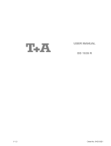
Notes on installing the AVR250
The inputs are named to make it easier to reference when connecting source components to the AVR250
(e.g., a DVD or VCR), but all inputs have the same circuitry. This means that there is no reason why you
should not connect a different device from that labelled to any of the inputs. For example, if you had two
DVD players and the AV input was not being used, then the second DVD player could be connected to
the AV input.
Cables
We recommend the use of high quality screened analogue, digital and video cables, since inferior
quality cables will degrade the overall quality of your system. Use only cables that are designed for the
particular application as other cables will have different impedance characteristics that will degrade
the performance of your system (for example, do not use cabling intended for audio use to carry video
signals). All cables should be kept as short as is practically possible.
Video and digital connections must be made with cables that are designed for this purpose, i.e., coaxial
cable with a 75Ω impedance. If substandard cables are used you may suffer from poor picture quality
such as ghost images and/or grainy picture quality (snow).
Speaker cables should be kept short to ensure ef cient power transmission and avoid audible distortion.
It is good practice when connecting your equipment to ensure that the mains power supply cabling is
kept as far away as possible from your audio and video cables, as this will provide the best sound and
picture quality. Failure to do so may result in unwanted noise in the audio and video signals.
TAPE
CD DVD-A IN AUDIO VIDEO DIGITAL IN
REMOTE
RS232 CONTROL
FR FL CEN RS LS RSB LSB
OUT
IN
VCR
OUT
IN
PVR
AV
SAT
DVD
S
C
MON
OUT
ZONE2
VIDEO
OUT
DIGITAL
OUT
CD
AV
DVD
SAT
PVR
TAPE
R
L
R
L
IN
IN
OUT
FR
RS
RSB
CEN
FL
LS
LSB
SUB
IN
ZONE
2
IN
LOCAL
OUT
1/RGB 2/S-VID
12V
TRIGGER
(Z1 & Z2)
VIDEO TRIGGER
AC
INLET
AV
DVD
OUT
SAT
AM
GND
HIGH QUALITY VIDEO IN
FM
(USA) 10K
(EU) 9K
AM STEP
GROUND
LIFT
GROUND
230
SPEAKER
IMPEDANCE
AUDIO
PREOUT
SUB.
The AVR250 rear panel

AVR250
E-6
AVR250
E-7
English
Audio connections
n
Wherever possible, connect both the analogue and digital outputs of digital sources. This enables
use of a digital input for the main zone and the corresponding analogue input for recording onto
an analogue tape deck or VCR, and for the Zone 2 output if used.
n
Take care to place the audio cables as far from any power supply cabling as is practically possible
to reduce hum and other noise problems.
Analogue audio connections
STEREO INPUTS
2
VCR,
4
PVR,
5
AV,
6
SAT,
7
DVD,
br
TAPE IN,
bs
CD.
Connect the left and right outputs of your source equipment to the left and right inputs.
Connection of record decks:
The AVR250 is not tted with a phono pre-ampli er. If you wish to connect a record deck
to the AVR250, then you will need an external pre-ampli er. Please contact your dealer for
further information and recommendations on the best option for your system.
MULTI-CHANNEL DVD-A/SACD INPUTS
8
RIGHT,
9
LEFT,
bk
RIGHT SURROUND,
bl
LEFT SURROUND,
bo
CENTRE,
bp
SUB.
Connect the audio outputs of your DVD-Audio or SACD player to these input sockets.
bm
RS BACK, and
bn
LS BACK.
These are available for formats requiring eight channels. Currently no formats are available
requiring these connections, which are provided for future compatibility.
The multi-channel input is intended for use with sources that decode the surround channels
internally, such as DVD-A or SACD players.
The AVR250 switches these analogue inputs directly to the analogue outputs via its own volume
control circuit. This direct path maintains the best possible sound quality for DVD-A and SACD
sources; it has the side-effect that there is no bass-management for DVD-A or SACD players. In
this case, the bass-management functionality of the player itself should be used.
STEREO OUTPUTS
1
VCR OUT,
3
PVR OUT,
bq
TAPE OUT.
Connect the left and right audio outputs sockets to the left and right input sockets of your cassette
deck, VCR or PVR (usually labelled ‘RECORD IN’). The VCR/PVR connections may also be used for a
second or third cassette deck.
Digital audio connections
INPUTS
cl
CD,
cm
DVD,
cn
AV,
co
SAT,
cp
PVR,
cq
TAPE.
Connect the digital ouputs of your available source equipment to these inputs.
If required, each of these six digital inputs can be allocated to a different audio input from that
indicated by the input label, through the ‘Digital Settings’ page of the Set-up menu. This means
that, for example, if you wish to use an optical connection for your DVD player, the optical
connection for the SAT, PVR, or TAPE can be used and the audio from that digital input assigned to
the DVD button.
OUTPUTS
bt
ck
DIGITAL OUT.
Two digital output connections are available: optical and coaxial. The two connections carry the
same information at all times and both may be used simultaneously. Connect the digital outputs to your
digital recording devices such as a CD-R, digital VCR or MiniDisc player.
When a digital source is selected, the digital output will send an exact copy of the incoming digital
signal. For example, for a 5.1 digital source, the digital output will also be in 5.1 format.
When an analogue source is selected, the digital output will be muted.
Subwoofer output
dl
AUDIO PREOUT SUB. Subwoofer output. Connect this to the input of your active subwoofer, if you
have one.
1
AUDIO
OUT
IN
VCR
OUT
IN
PVR
AV
SAT
DVD
R
L
2
3
4
5
6
7
DVD-A IN
FR
RS
RSB
CEN
FL
LS
LSB
SUB
same information at all times and both may be used simultaneously. Connect the digital outputs to your
DIGITAL IN
DIGITAL
OUT
CD
AV
DVD
SAT
PVR
TAPE
AUDIO
PREOUT
SUB.
TAPE
CD
R
L
IN
IN
OUT

AVR250
E-8
AVR250
E-9
English
Video connections
The AVR250 allows for conversion between different video
formats. This means that the AVR250 can convert between
composite, S-video and component, if required.
For example, if you are watching a composite input from a VCR,
you may view it from the S-video or Component/RGB video
outputs of the AVR250. This allows you to use a single (typically
high-quality Component/RGB) connection between the AVR250
and your display device.
The record loops do not work from the video converter.
This means that to record a S-video or composite signal,
a S -video or composite signal (respectively) must be
supplied.
Composite/S-video video connections
dm
dn
MONITOR OUT.
Two video output connectors are provided, one for S -Video and one for composite video. The
outputs carry the same information at all times (and both may be used simultaneously, if required).
Connect one of these outputs to the video input of your display device.
dq
VCR IN,
ds
PVR IN,
dt
AV,
ek
SAT,
el
DVD.
Connect the composite video outputs of your source equipment to these inputs. The choice of
connection to use (S-video or composite) depends on where the signal is to be routed to: if the
signal is to be used in Zone 2, then a composite connection is required; if the signal is to be used
for recording (routed to a VCR, for example), then the connection type must match the connection
to the recording device (i.e., if the recording device requires a S-video signal, then a S-video
connection from the source equipment must be used).
If both connections are made, the signal from the S-video input will be used for the main zone if no
Component/RGB signal is supplied.
dp
VCR OUT,
dr
PVR OUT.
Connect one of the S-video or composite video outputs to the video input of your VCR or PVR. The
connection used must match the video type of the source you wish to record (as described above).
For example: if you wish to record a S-video signal from your satellite receiver on your VCR, the
connection to the VCR must also use S-video.
High quality (Component) video connections
These inputs are suitable for connection to component (YUV/YCrCb) or RGB outputs. These
signals are usually available from a DVD player, set-top box or games console and offer the
best possible picture quality.
Note that the high-quality component video connections operate independently of the
composite/S-video connections.
Generally, the component video standard is used in North America/NTSC regions, while RGB
is used in Europe.
em
AV,
eo
DVD,
ep
SAT INPUTS. Connect the video outputs of your high-quality video
sources to these inputs.
en
HIGH QUALITY VIDEO OUT. Connect these sockets to the component video inputs of your
display device.
Important notes about HQ-video inputs and outputs
n
In the ‘Video Settings’ set-up menu, each of these three high-quality component video
inputs can be allocated individually to any of the other inputs, e.g., the input labelled
“DVD” does not have to be used for DVD, but can be used for something else. See page
14 for further details.
n
You cannot mix component and RGB sources. Selection of component or RGB can be
made in the Set-up menu ‘General Settings’ page (see page 10).
n
The high-quality component video inputs have suf cient bandwidth for line-doubled
NTSC (525/60) or PAL (625/50) video (“progressive scan”) and also US HDTV video
signals. However, when used with such signals the OSD is not overlaid on the picture
but is output at standard interlaced NTSC or PAL (525 or 625 line) rate on a solid
background.
n
When using the HQ-video inputs, the composite and S-video outputs will be muted. This
is because the processing for the on-screen display would create invalid video signals on
these outputs.
SCART RGB 4-WIRE CONNECTION
(SCART refers to the multipole A/V connector used commonly on European A/V equipment.)
Some video projectors and most European TV sets require the use of a 4-wire RGB connection, where
the ‘sync’ signal is separate from RGB. In this case, you need to use the composite video MONITOR
OUT
dn
for the sync information. A cable is available from your dealer to make this 4-wire RGB
connection (refer to the table of SCART connections at the back of the manual). Note that use of this
feature requires (in addition to the RGB connections) a composite video connection between the source
and the AVR250, in order to supply the additional synchronisation signal.
Note that most SCART TV inputs will require the SCART RGB status line to be controlled before the RGB
signal will be displayed. The RGB trigger output will control this signal when connected to the SCART
socket using a cable of the type given on page 32. These cables are available from your dealer.
The AVR250 does not support either 5-wire RGB HV or 3-wire RGB sync-on-green connections.
VIDEO
OUT
IN
VCR
OUT
IN
PVR
AV
SAT
DVD
S
C
MON
OUT
ZONE2
VIDEO
OUT
AV
DVD
OUT
SAT
HIGH QUALITY VIDEO IN
The following video conversions are possible:
To:
From:
Composite S-video Component/
RGB
Composite Yes Yes Yes
S-video Yes Yes Yes
Component/
RGB
No No Yes
Note that conversion between RGB and Component video
(or vice-versa) is not supported by the AVR250.
When you connect
your devices to these
connectors, take care to
follow the letter/colour
coding for each input.
No damage will occur if
connected incorrectly,
but unusually coloured
or unstable pictures will
result.

AVR250
E-8
AVR250
E-9
English
Connecting loudspeakers
The red and black terminals on the back of the AVR250 are used to make the connections to the
loudspeakers. The speakers should be connected to the loudspeaker terminals, refering to the
labels on the rear-panel.
When connecting the speaker terminals of the ampli er with the terminals on the speakers make
sure that like polarities are matched (i.e., match “+” with “+” (usually red) and “–” with “–”
(usually black)). Mismatching of polarities will result in a weak central sound, unclear orientation
of the instruments and the sense of direction of the stereo being impaired.
There are two options for connecting the speaker cable to the ampli er:
Using bare wire ended leads:
1. Strip back the insulation on the wire to reveal about 2cm of conductor (the metal inside
the cable).
2. If the conductor is stranded, twist the strands together tightly to avoid loose strands making
contact with the adjacent terminals or the back panel.
3. Loosen the terminal by turning it anti-clockwise
4. Insert the twisted wire through the hole in the terminal.
5. Tighten by turning clockwise.
When making connections with stranded bare ended wires, take great care that no individual strands of
wire come into contact with the adjacent terminals or with the back panel. If this should happen, it will
cause a short circuit on the output of the ampli er and could damage the ampli er.
Using spade terminals:
1. Loosen the terminal by turning it anti-clockwise
2. Insert the spade connector under the terminal.
3. Tighten by turning clockwise.
Speaker impedance
Before connecting loudspeakers to your AVR250 you must set the impedance switch on the rear to the
correct position (never adjust this switch with the power on or you may damage your speakers). If your
loudspeakers are rated at 6Ω or lower set the switch to the 4Ω position; if your loudspeakers are rated
higher than 6Ω, set the switch to the 8Ω position. This unit should only be used with loudspeakers with
an impedance rating above 4Ω.
Note that failure to set this switch correctly for your speakers may cause the ampli er to shut down due
to overheating.
Zone 2 connections
The AVR250 allows independent routing and control of analogue audio and composite
video to a second room such as a kitchen, bedroom or lounge. This second room is known
as ‘Zone 2’.
For Zone 2, the AVR250 outputs a line-level audio signal taken from the stereo analogue
audio, and a composite video signal taken from the composite video input (for a given
source). The analogue inputs are required because there is no analogue-to-digital, DSP
processing or digital-to-analogue conversion available for Zone 2 signals. As the AVR250
does not convert video formats for Zone 2, a composite video signal must also be
connected from the source.
For these reasons, we recommend that source devices that have a digital connection are
also connected via the analogue inputs. High quality YUV/RGB and S-video sources should
also have their composite video outputs connected to the AVR250 for use in Zone 2.
NOTE: As a composite input is required for Zone 2, it may not be
possible to run your DVD player in progressive scan mode and to use
Zone 2 at the same time, unless your DVD player can output both
progressive scan and composite signals simutaneously.
eq
ZONE 2 OUT.
This is the audio output for Zone 2. Connect these to a line level input on
your Zone 2 ampli er.
do
ZONE 2 VIDEO OUT (Composite video connection).
This is the video output for Zone 2. Connect to your Zone 2 video display
using 75Ω low loss coaxial cable.
fk
IN ZONE 2.
This allows the AVR250 to be controlled remotely from Zone 2 via infrared
remote control. See the panel for connection information.
MON
OUT
ZONE2
VIDEO
OUT
ZONE
2
REMOTE
IN
ZONE
2
IN
LOCAL
OUT
12V
TRIGGER
(Z1 & Z2)
Zone 2 remote controller connection.
A receiver compatible with this connector
fk
is
available from Xantech (part no. 291-10). Please
contact a Xantech registered dealer for this part,
as ARCAM does not stock them.
See www.xantech.com for more information.
The 3.5mm jack plug for this connector is wired
as follows:
3.5mm stereo jack Function
Tip Signal
Ring 0V
Sleeve 12V,
30mA current-limited
This follows the Xantech standard for IR
transmission over wire.
SPEAKER
IMPEDANCE
The speaker connectors
on the rear-panel are
labelled as follows:
FL - Front Left
FR - Front Right
CEN - Centre
RS - Right Surround
LS - Left Surround
RSB - Right Surr. Back
LSB - Left Surr. Back

AVR250
E-10
AVR250
E-11
English
Connecting the AM and FM antennas
FM antenna
An FM antenna is required to receive VHF radio signals.
Although a FM ribbon antenna is supplied as an accessory to the AVR250, for optimal FM radio reception
a roof- or loft-mounted aerial is advised as this will give superior reception. (It is recommended that any
roof-top antenna is tted by an experienced contractor as a contractor will be able to align your antenna
to the nearest FM transmitter.)
In some areas cable radio may be available or, in an apartment building, a distributed antenna system
may be installed. In either of these cases you should have sockets in your home marked FM or VHF (do
not use those marked TV), which should be connected to the FM in socket
fr
of the AVR250.
If you wish to use the supplied FM ribbon cable, mount this as high up as possible on a wall with the ‘T’-
elements positioned horizontally. Try each usable wall of the room to see which gives best reception and
use tacks or adhesive tape to secure the aerial in a T shape (note that no tacks should come into contact
with the internal wire of the aerial). When assembled (see box, right), the plug on the ribbon cable
should be connected to the FM in socket
fr
of the AVR250.
AM antenna
An AM antenna is required to receive AM/medium wave radio signals.
An AM loop antenna is supplied as an accessory with the AVR250. This should be attached to
the AM antenna inputs
fq
with one end connected to AM and the other to Ground (it does not
matter which way round this antenna is tted). Rotate the antenna to discover which position
gives the best reception.
In areas of weak reception, or when the AVR250 is in use inside a steel framed building (such
as an apartment building), you can use a wire between 3 and 5 metres long to strengthen
reception. Mount this high up outside the building (if possible) and connect one end of this wire
to the AM antenna input in addition to the loop aerial supplied (do not disconnect the AM loop
antenna).
AM STEP SIZE
The AM tuning ‘step size’ needs to be set according to your location. This is done using the switch on the
rear panel
fs
: set it to 10kHz if you are in North America or 9kHz anywhere else. Note that this should
be set correctly even if you do not intend to use AM reception as it also alters some FM tuner settings
for use in North America.
Control connections
es
(REMOTE) OUT. This outputs any remote control signal that is received by either the front panel or
from one of the remote control connections. It allows remote control of source components; control is
possible by either connecting this output to the devices to be controlled via the 3.5mm IR jack socket
(Arcam units only) or by using an IR emitter stuck to the centre of the IR sensor window on the source
component (such as a Xantech 283MW mini emitter).
et
IN LOCAL. Use with a local IR receiver when the AVR250 front panel IR receiver is obstructed.
fk
IN ZONE 2. This allows the AVR250 to be controlled remotely from Zone 2 via infrared remote
control (see section ‘Zone 2 connections’ above for further details).
fn
RS232 CONTROL Use with control devices having an RS232 serial port (for example, Crestron and
AMX touch screen controllers). This connection is also used for upgrading control software. See the
sections at the end of this manual for control and programming information.
Trigger outputs
There are three trigger output sockets on the AVR250, each of which is
a 3.5mm stereo jack with two contacts, ‘tip’ and ‘ring’. See the tables for
technical information on the trigger outputs.
er
12V TRIGGER. This can be used for turning on and off automatically
power amps or source equipment for the main zone and Zone 2. The trigger
lead is wired as shown in the panel.
fm
VIDEO TRIGGER 1,
fl
VIDEO TRIGGER 2. These trigger outputs have
different functions depending on how the ‘Video Status’ has been set in the ‘General Settings’ menu. See
page 10 for full details.
Connecting to a power supply
fo
POWER INLET. The AVR250 has a dual voltage power supply that can be switched between 120V and
230V AC. As supplied, this switch should be set correctly for your local supply.
fp
GROUND LIFT switch. In complex set-ups that include satellite inputs or radio antennas, grounding
the unit may increase the level of background hum or buzz in the loudspeakers. If this occurs, set the
GROUND LIFT switch to lift the signal ground from the chassis ground.
DO NOT REMOVE the safety earth from the mains cable under any circumstances.
Mains lead
The appliance is normally supplied with a moulded mains plug already tted to the lead. Check that the
plug supplied with the unit ts your supply. If your mains plug is different, consult your Arcam dealer.
If for any reason the plug needs to be removed, it must be disposed of immediately and securely, as it
is a potential shock hazard when inserted into the mains socket. Should you require a new mains lead,
contact your Arcam dealer.
Plugging in
Push the plug (IEC line socket) of the power cable supplied with the unit into the power input socket
(
fo
) in the back of the unit. Make sure it is pushed in rmly.
Put the plug on the other end of the cable into your power supply socket and switch the socket on.
REMOTE
RS232 CONTROL
IN
ZONE
2
IN
LOCAL
OUT
1/RGB 2/S-VID
12V
TRIGGER
(Z1 & Z2)
Connection Function Voltage
Tip Main zone on On = 12V, 30mA
Off = 0V
Ring Zone 2 on On = 12V, 30mA
Off = 0V
Sleeve Ground 0V
AC
INLET
GROUND
LIFT
GROUND
230
fo
fp
AM
GND
FM
(USA) 10K
(EU) 9K
AM STEP
fq
fr
fs
Connecting the plug to
the FM ribbon cable:
1) loosen the two screws
on the plug;
2) insert the spade
connectors of the ribbon
cable under the screws;
3) re-tighten the screws
onto the connectors.

AVR250
E-10
AVR250
E-11
English
Con guring the AVR250
The AVR250 ‘Set-up Menu’ has six ‘Basic’ and ve ‘Advanced’ menu screens that take you through
the con guration process. The ‘Basic’ menus enable you to match your AVR250 to your speakers; the
‘Advanced’ menus allow you to optimise the operation of your system. Screen shots of these menus are
shown in shaded boxes on the following pages.
The best way to set up the AVR250 is using the on-screen display (OSD). To view the OSD for the initial
set up, use the composite video output to connect to your TV. This is because the high quality video
output has several display modes and may be incompatible with your high quality display device in its
default con guration.
Set-up mode
To enter the Set-up menus press and hold the MENU button on the remote control or on the front panel,
for at least two seconds. The ‘Set-up Menu Index’ is displayed on your display device.
Set-up Menu Index
The Set-up menu index page is the rst page that is displayed when the Set-up menu is
entered. This page allows you access to the six ‘Basic’ and ve ‘Advanced’ menus.
Navigating the Set-up menu
... BY USING THE REMOTE CONTROL
The Set-up menu can be navigated by using the cursor (arrow) keys on the remote
control. This is by far the easiest method.
1. To enter the Set-up menu, press and hold the MENU button (which is located
immediately under the navigation buttons) for at least two seconds, until the
Index page appears. (Pressing the menu button for just a short time will take
you to ‘Main Menu Screen 1’. If this happens, the Main Menu can be closed by pressing MENU for
a second time.)
2. When the menu heading is highlighted, using the
3
and
4
keys will navigate between menu
pages. Using this method to navigate between pages the rst time the unit is being con gured
will help to ensure that no pages are missed out.
3. Use the
5
and
6
keys to navigate up and down the menu lines.
4. To change the setting for a particular menu item, highlight the item then use the
34
keys to
cycle through the options for that item.
5. Once you have set all the menu items on a page to have values that are appropriate for your
system, move the menu highlight to the top of the screen (the menu heading) and press
4
to
move to the next menu page.
6. At any time, press the MENU button to return to the main Set-up menu index screen.
7. To save the changes you have made, return to the Set-up menu index page and highlight the
‘Save Set-up’ item at the bottom of the screen. Press the OK button to save the settings. Press
OK again to exit the Set-up menu.
In addition to the above method of moving from page to page using the
34
keys, each menu page
can be accessed directly from the Set-up menu index page. This is achieved by using the cursor keys to
move the menu highlight to the desired page on the Index page, then pressing OK.
... BY USING THE BUTTONS ON THE FRONT PANEL OF THE AVR250
The AVR250 front panel controls can be used to con gure the options. Follow the instructions given for
using the remote control, in this case using the EFFECT/
6
button for ‘down’, the MODE/
5
button for
‘up’ and the volume control for left and right.
MENU
OK

AVR250
E-12
AVR250
E-13
English
The ‘Basic’ Set-up Menus
1 – General Settings:
Max Volume: This limits the maximum volume setting the system can be turned
up to. This is a useful feature to prevent accidental overdriving of low power-
handling speakers, for example.
Max On Volume: Limits the maximum volume the system operates at when it is
rst switched on. The system comes on at the ‘Max On Volume’ if the last used
(possibly very loud) volume exceeds this value.
Delay units: Controls whether the delay settings for the speakers in surround
modes are speci ed in Imperial or Metric measurements from the listening
position, or in terms of time. Either enter the time delay to each channel if
calculating the delay in milliseconds, or select between Imperial or Metric
measurements and allow the AVR250 to calculate the time delay automatically.
Imperial is measured in feet and Metric is measured more precisely in 0.1m
(10cm) increments (1 foot is approximately 0.3 metres).
Note that changing the units resets all distances/times to zero. It is therefore
important to choose the units (Time, Imperial or Metric) before set up.
OSD Mode: Controls how the on-screen display is viewed.
n
MIXED: the OSD will appear on top of the existing video picture
n
FULL PAGE: the OSD is displayed in white on a full screen black background.
On video signals that have a sync rate of greater than the normal interlaced rate (i.e.,
progressive scan, frame-scaled video, HDTV) the OSD will automatically go into Full Page mode
(black background) so that the control menu can be accessed. Any pop-up displays (such as the
volume bar, source selection information, etc) will be switched off.
Video Status: The video status control is intended for use with SCART connections, but may nd
use for other purposes. It is possible to use a SCART connection between the AVR250 and your
television even though the AVR250 does not have a SCART socket; a pin-out for a SCART lead
suitable for this purpose is given on page 32. We suggest the ‘SQART’ cables manufactured by
QED (www.qed.co.uk); please ask your dealer for details.
This setting controls the two video triggers
fl
fm
on the rear panel and is used to inform the
AVR250 which type of video connection is present between it and your TV, in order that the
AVR250 can set the control lines correctly for SCART connections. Note that if you do not wish to
use the video triggers or a SCART connection, then it does not matter which value this item has.
This item has four settings: COMPOSITE, S-VIDEO, RGB and SCRN CTRL.
COMPOSITE: This mode is used to indicate to your TV that composite video is being sent. It uses
the trigger labelled 1/RGB
fl
(which should be connected to the RGB SCART input on your TV),
as shown. Select this option if you are using the composite video output of the AVR250.
The 2/S-VIDEO trigger is not active in this mode.
S-VIDEO: This mode is used to
indicate to your TV that S-video is
being sent. It uses the trigger labelled
2/S-VIDEO
fm
, as shown. Select this
option if you are using the S-video
output of the AVR250.
Note that, if this option is selected,
the connection labelled ‘S-video
SCART’ (or similar) must be used on
the TV, as not all SCART connectors
are wired for S-video.
The 1/RGB trigger is not active in this
mode.
RGB: This mode is used to indicate to
your TV that RGB video is being sent.
It uses the trigger labelled 1/RGB, as
shown. Select this option if you are
using the RGB output of the AVR250.
If this option is selected, the
connection labelled ‘RGB SCART’ (or
similar) must be used on the TV, as
not all SCART connectors are wired
for RGB.
The 2/S-VIDEO trigger is not active in
this mode.
SCRN CTRL: The two video triggers on
the rear panel have the same signal
for all outputs. This will be +12V
when any video source is selected,
otherwise 0V. This can be used (for
example) to unfurl projector screens
automatically when a video source is
selected.
1/RGB trigger output with COMPOSITE selected:
Connector Function Voltage
Tip RGB mode select 0V
Ring RGB/composite SCART input
select (CVBS status)
Aspect ratio 4:3/16:9
Video present, aspect 4:3 = 12V
Video present, aspect 16:9 = 6V
No video signal = 0V
Sleeve Ground 0V
2/S-VIDEO trigger output with S-VIDEO selected:
Connector Function Voltage
Tip Video source trigger Any video source selected = 12V
No video source selected = 0V
Ring S-video SCART input select
(CVBS status)
Aspect ratio 4:3/16:9
Aspect 4:3 = 12V
Aspect 16:9 = 6V
No video signal = 0V
Sleeve Ground 0V
1/RGB trigger output with RGB selected:
Connector Function Voltage
Tip RGB mode select RGB video = 1V (into a 75ohm
load)
Ring RGB/composite SCART input
select (CVBS status)
Aspect ratio 4:3/16:9
Video present, aspect 4:3 = 12V
Video present, aspect 16:9 = 6V
No video signal = 0V
Sleeve Ground 0V
1/RGB and 2/S-VIDEO trigger outputs with SCRN CTRL selected:
Connector Function Voltage
Tip Main zone on trigger Main zone turned on = 12V
Main zone turned off = 0V
Ring Main zone on trigger Main zone turned on = 12V
Main zone turned off = 0V
Sleeve Ground 0V

AVR250
E-12
AVR250
E-13
English
HQ Video: Choose between RGB or YUV; if you have a YUV display, set this item to YUV, otherwise
set it to RGB.
This setting controls the routing of the HQ-video within the AVR250, either as 3-wire YUV or 4-
wire RGB signals (with the synchronisation signal on composite for RGB). In addition, it controls
the operation of the S-video/composite-to-HQ video converter.
When set to YUV, incoming composite and S-video signals are converted to YUV; in RGB mode,
the iincoming signals are converted to RGB, with the synchronisation signal on the composite
output.
2 – Speaker Sizes
The size and number of loudspeakers are de ned on this page.
Auto Set-up: Allows the setting of ‘standard con gurations’ as in the table below:
Speaker Con g. 1 Con g. 2 Con g. 3 Custom
Front L/R Small Large Large Small/Large
Centre Small Small Small Small/Large/None
Surr L/R Small Small Large Small/Large/None
Surr Back L/R Small Small Small Small/None
Sub-woofer Present None Present Present/None
5.1 Rears Both Both Both Surr L/R/
Sur Back L/R/
Both
The Custom setting allows you to choose any combination of speakers to suit your system. Note that
the centre and rear speakers cannot be set to ‘large’ if the front speakers are set to ‘small’.
5.1 Rears de nes how the speakers in a full ‘7.1’ installation handle 5.1 decoded sources.
n
SURR L/R redirects 5.1 surround signal to the surround left and right speakers. No signal will be
directed to the surround back left or right speakers.
n
SURR BACK L/R redirects 5.1 surround signal to the surround back left and right speakers. No
signal will be directed to the surround left or right speakers.
n
BOTH redirects the 5.1 surround signal to both pairs of speakers with the signal to each set
reduced by 3dB.
A note on speaker sizes:
A Large speaker is one that is capable of handling a full range signal (i.e., 20Hz–20kHz).
A Small speaker is one that is not capable of reproducing a deep bass signal (i.e., below 100Hz),
for example a satellite speaker.
None indicates that there is no speaker connected to that channel.
3 – Subwoofer Settings
If no subwoofer was selected in the previous speaker menus then some of the items on
this page will not be adjustable.
Cross-over Freq.: This setting de nes the frequency at which bass redirection begins.
Frequencies below this level are redirected from ‘small’ speakers to the Fronts or to
the subwoofer; frequencies above this level are not redirected. The value for this
setting depends on your speakers, environment and taste, and is best determined by
experimentation.
The adjustment can be made in increments of 10Hz between 40Hz and 130Hz.
Stereo Mode: Select between Large, Large+Sub or Sat+Sub.
If you have con gured your system to have a subwoofer, then you have the exibility
to choose how bass information is distributed between the front left/right speakers and
the subwoofer when listening to stereo sources. Choose the option which gives you the most solid even
sounding bass (for best results test with a set-up disc or live program material).
n
LARGE: Pure stereo information — all audio is sent to the front left and right speakers. Use this
setting if you have large front speakers.
Note that this option will override the setting con gured on the “Speaker Sizes” menu page.
n
LARGE+SUB: Pure stereo is fed to left and right and extracted bass is sent to the subwoofer. In
this case the low frequency information is, effectively, duplicated.
n
SAT+SUB: Use this setting if you have ‘Small’ satellite left and right speakers. Full bass
management is used in analogue stereo so that analogue sources are fed to the DSP where the
bass is ltered off left and right and redirected to the subwoofer.
Note that the above three Stereo Mode settings pass the audio through the DSP, which may degrade
the sound quality slightly. This can be avoided for the ‘Large’ setting by pressing the DIRECT button to
bypass the DSP processing.
DTS LFE Gain: DTS soundtracks typically have the LFE track recorded 10dB lower than the main audio
tracks. It is, therefore, necessary to compensate for this by raising the LFE output level by 10dB, and
setting the DTS LFE gain to ‘Normal’ activates this compensation. Some DTS soundtracks have been
recorded with the LFE signal at the same levels as the main audio, however, and therefore require no
gain compensation. For these disks set the DTS LFE gain to -10dB.
n
NORMAL: This increases the LFE signal by 10dB and is the recommended setting for the AVR250.
n
-10DB: This allows the LFE to pass directly to the output with no gain adjustment.
Unfortunately, there is no rule for determining which discs are recorded using which method. As a
general guide, however, it is only early DTS music discs that require the -10dB setting.

AVR250
E-14
AVR250
E-15
English
Sub Stereo: This setting allows the volume level of the subwoofer to be adjusted for when the
subwoofer is being used with 2-channel (stereo) sources. The subwoofer level for stereo music often
needs to be set at a lower level than that for cinema use; use this trim setting, with a stereo source, to
reduce the subwoofer output in stereo playback to an acceptable level. The level required depends on
various factors such as speakers, the types and styles of music to be played and personal taste.
DVD-A Sub Level: This setting allows compensation for subwoofer level gain from external decoders or
sources (such as DVD-A players).
When decoding digital inputs, the AVR250 follows the convention for products of this type and sets the
subwoofer level 10dB higher than that of the other channels. Source products such as DVD-audio players
do not follow this pattern, however, setting the subwoofer level to be the same as the other channels.
This means that switching from material that has been decoded by the AVR250 to that decoded
externally may mean that the subwoofer sounds very quiet. This setting provides for the removal of that
difference by allowing the subwoofer level of the DVD-A (multi-channel) input to be raised by 10dB.
n
NORMAL: No gain compensation. This allows the DVD-A sub level to pass directly to the output
with no gain adjustment.
n
+10DB: This increases the DVD-A (multi-channel input) sub level by 10dB
If you are using the AVR250 in combination with the multi-channel analogue outputs of an Arcam DVD-A
player, then this item should be set to ‘+10dB’.
4 – Speaker Delay Settings
The relative positioning of speakers within a room may mean that sound from some
speakers arrives at the listener later
than sound from others. By altering
the delay settings for the different
speakers, this difference in arrival time
can be reduced or eliminated.
When setting the delay, it should be
imagined that the listener is sitting
in a circle of the speakers; the delay
indicates the distance of the speaker
from the listener.
The speaker distance control can be
used to set automatically the appropriate time delays
required for all the speakers in your system. To use this,
measure from the usual listening position to the front
of each individual speaker in the system and enter this
value in the appropriate place. The measurements can
be entered either in feet or metres, as selected from the
‘General Settings’ menu page.
An alternative to using the speaker distance control is to
enter the delays manually in milliseconds.
Note that the delay adjustment is not a substitute for
proper speaker placement, but can help to ensure
accurate and correct signal arrival times from all the
channels to the primary listening position.
No measurement can be entered for a speaker that is
not selected in the previous ‘Speaker Sizes’ menu.
Note: Only enter these delay settings once you have speci ed which delay units (i.e., Time, Imperial
or Metric) you will be using. The delay settings will be lost if the units are changed.
If the delay units are set to Time, then enter the delay in milliseconds for each channel.
Fr
ont
left
Surr
left
Surr
right
Surr
back
left
Sub
woofer
Fr
ont
right
Centre
e.g. 3m
(9ft)
e.g. 4m
(12ft)
e.g. 2m
(6ft)
Surr
back
left
Surr
back
right
Distance measurements for 5.1 [and 7.1]
speaker delay settings

AVR250
E-14
AVR250
E-15
English
5 – Level settings
The relative sensitivity of different speakers can lead to some speakers sounding
disproportionately loud or quiet, relative to others in the system. The level settings of
your AVR250 can help to address this inbalance.
It is important to calibrate the speakers correctly to achieve an accurately centred sound
stage. If possible, we recommend you use a sound pressure level meter (SPL meter)
to perform this part of the set-up as it is dif cult to judge the levels accurately by ear
alone.
Test Tone Cycle
n
MANUAL is best for setting up with a SPL meter as the test tone will not change
to the next speaker until instructed by you. Pink noise is emitted by the
highlighted speaker; when you wish to measure a different speaker, move the
highlight to the new speaker.
n
AUTO is best for setting up by ear. In this state, the test tone changes automatically between
speakers after a two second burst of sound.
On rst installation, watch the OSD display as you cycle through the available speakers with the test
tone. Check that the speaker generating the sound corresponds to that indicated on the OSD. If there is
a discrepancy then check and correct the system cabling before proceeding further.
To calibrate the speakers with a SPL meter, place the meter at ear level with the microphone pointing
towards the ceiling, when seated in the usual listening position. (You will need to set the meter to ‘C’‚
setting with a ‘slow’‚ response and to read 75dB SPL at the centre of the scale.) If you do not have a SPL
meter, simply set the front left speaker to 0dB on the menu and then match all the other speakers to
this level.
Each speaker can be ne-tuned by 1dB increments to ±10dB. The output from each speaker needs to be
adjusted to the 75dB SPL sound level. No adjustments can be made for a speaker that is not selected in
the previous ‘Speaker Sizes’ menu.
Note that inserting headphones into the front panel of the AVR250 will cause all test-tones to be muted
(including the headphone output).
Note: If you are using a 6.1 speaker con guration (a single surround back speaker), we recommend
connecting the surround back speaker to the surround back left channel of the AVR250.
In this case, the level of the connected surround back channel should be increased by 3dB (i.e., the
SPL meter should show a response of 78dB for this channel).
6 – EX Settings
Surr. EX: This can either be set to AUTO or MANUAL and is applicable only when playing
‘Surround EX’-encoded material.
n
AUTO DD EX: The AVR250 will switch automatically to ‘Surround EX’ decoding
when suitably encoded material is detected (this can be temporarily overridden
by pressing the MODE button on the remote control).
n
AUTO PLIIX MOVIE: The AVR250 will switch automatically to ‘Pro Logic IIx Movie’
decoding when suitably encoded material is detected (this can be temporarily
overridden by pressing the MODE button on the remote control).
n
MANUAL: The AVR250 will not select Surround EX automatically. It can however
be selected manually by pressing the MODE button.
Use Channels 6+7 for
Choose one from:
n
DOLBY SURR EX: ‘Dolby Surround EX’ provides two additional rear channels from 5.1 channel
EX-encoded material. This is intended to give better effects steering. In this mode, ampli er
channels 6 and 7 are used to drive the EX speakers.
n
ZONE 2: In this mode, ampli er channels 6 and 7 are used to provide speaker level output for
use in Zone 2.
n
BIAMP L+R: The ampli er channel 6 and 7 are used to provide a second ampli ed output of the
left and right channels. This allows you to bi-amplify your front speakers, which should give an
improvement in the sound quality of these channels.
If you would like to do this, please refer to page 26 for further information.
Note: Changing this setting will require you to change the con guration of the cables connected your
speakers.
English

AVR250
E-16
AVR250
E-17
English
The ‘Advanced’ Set-up Menus
ADV 1 – Speaker Eq.
This allows ne adjustment of bass and treble in 1dB steps (up to ±6dB) for each of the
speakers in the system. Use these adjustments sparingly to compensate for speaker
response problems caused by positioning, adjacent surface textures, or mixed brands of
loudspeakers.
Work with one speaker on at a time and, as an example, use the bass control to reduce
boom problems for speakers placed in corners, and the treble control for speakers
placed near re ective surfaces. We recommend trying to obtain a good speaker
response by speaker placement rst, then apply speaker equalisation last.
The tone control nominal corner frequencies are at 100Hz and 8kHz, shelf type.
Auto Stereo Tone Bypass: Set this item to YES if, when a stereo input signal is
detected (analogue or digital), the tone adjustments set on this page are to be by-
passed. (Note that this does not switch the AVR250 into ‘Direct’ mode, it simply sets the tone controls to
zero.)
ADV 2 – Video Settings
This menu allows advanced adjustment of the video settings for your AVR250.
Zone 1 OSD: Selects whether the main zone OSD is on or off.
n
When set to ON‚ all user adjustments that are made during the general use of
the AVR250 are displayed on the screen. This includes the adjustment of the
volume control, the inputs selected and the set-up menus.
n
When set to OFF‚ there will be no display of the general user adjustments – only
the set-up menus and the main menus are displayed.
It is recommended you keep the OSD turned ON‚ since if you cannot see the front panel
of the AVR250 you will have no idea if any adjustments you have made to the processor
are correct or to your liking.
Video Inputs
: Composite and S-video inputs for DVD, Sat, AV, VCR and PVR have their audio and video
assigned to track each other by default. The ve ‘Video Input’ lines for Tape, CD, FM, AM and DVD-A
allow assignment of a video source to these normally audio-only sources. If desired, it is possible to
allocate the same video source to more than one audio input. This facility allows you to listen to an audio
source and view a separate video source at the same time – for example, you can listen to radio while
watching TV for a sports simulcast.
HQ Video DVD, AV and SAT: Allocate the high quality component or RGB video inputs to any source
buttons. For example, to assign the Component/RGB video from the ‘HQ Video DVD’ input to the DVD
button, set the ‘HQ Video DVD’ item in this menu to ‘DVD’.
If HQ-VIDEO is set to RGB (as described on page 13) and an HQ-video input is assigned to a button,
the AVR250 assumes that RGB signals are present for that input if a composite signal is found on the
corresponding composite input. If this assignment is made but no RGB signals are supplied, the
display will be blank for the assigned source.
ADV 3 – Digital Settings
Coaxial inputs and Optical inputs. Each of the digital inputs can be assigned to any
of the seven stereo source buttons (CD, TAPE, DVD, SAT, AV, VCR and PVR), or can be
assigned No button.
This menu page lists the physical inputs, as per the back panel, on the left hand side of
the screen, with the buttons used to select the inputs listed on the right hand side.
Each digital input can be allocated only to one source button. For example, if you choose
the ‘Coaxial DVD input’ to be assigned to the DVD button, then the choices for the other
digital inputs are: CD, TAPE, SAT, AV, VCR, PVR and NO BUTTON. If you wish to re-
allocate the DVD input to a different button, ‘Coaxial DVD input’ must be assigned to a
different button (or No button) before you can re-assign the DVD input.
: Composite and S-video inputs for DVD, Sat, AV, VCR and PVR have their audio and video

AVR250
E-16
AVR250
E-17
English
English
ADV 4 – Zone 2 Settings
ZONE2 VOL: Sets the volume for Zone 2.
Max Vol 20–83: Limits the maximum volume setting for Zone 2. This is a useful
feature to prevent accidental overdriving of low power-handling speakers, for example.
Fix Vol: This selects between xed and variable audio output to Zone 2. If NO is
selected, the output level can be controlled from Zone 2 or the main system. If you wish
to x the volume level, rst set the Zone 2 volume to the desired level, then select YES.
Max On Vol: Limits the maximum volume Zone 2 operates at when it is rst switched
on. Zone 2 comes on at this volume if the last used volume exceeds this value.
Stand-by: This allows zone 1 (the main zone) to be put into stand-by, either locally
only or by Zone 2 as well.
n
LOCAL ONLY: Only the main zone will be switched into stand-by from the main zone.
n
ALL OFF: Both the main zone and Zone 2 will be switched into stand-by from the main zone.
Access: This acts as a ‘parental control’ device to disable or enable access to sources for Zone 2.
Press the unwanted source button on the remote control handset or front panel to disable it for Zone 2.
Press again to enable the source.
Enabled sources are listed on the ‘Access:’ line of the menu page.
Note: if a source is already in use in Zone 2 when access to it is removed, the source remains active
until a different source is selected in that zone. After this time, the original source is unavailable.
ADV 5 – Analogue Settings
Input trims: Allows the adjustment of the input sensitivity of the analogue inputs (in
Volts rms) so that each one achieves the optimum dynamic range and sounds similar in
loudness to the others.
Available level settings are: LOW 0.5V, MEDIUM 1V, REFERENCE 2V, HIGH 4V. The
reference level of 2V should be appropriate for most inputs.
If a source is very quiet compared with the other sources you can increase its loudness
by selecting the MEDIUM 1V or LOW 0.5V settings.
Saving Settings and Exit Set-up
You can either save the settings now or exit without saving the changes.
Save Set-up
1. Press MENU to go to the ‘Set-up Menu Index’ at the ‘Save Set-up’ point.
2. Press OK to save.
3. Press OK to select ‘Exit Set-up’ and exit system con guration.
Exit without saving
If you choose to ‘Exit Set-up’ without rst saving the changes, then the new settings will be lost.
1. Press MENU to go to the ‘Set-up Menu Index’ at the ‘Save Set-up’ point.
2. Press
4
to select ‘Exit Set-up’.
3. Press OK when ‘Exit Set-up’ is selected to exit system con guration.

AVR250
E-18
AVR250
E-19
English
Remote control
SELECT DEVICE
SET
LAST
SLEEP
A–B
EXIT
GUIDE
CH
VOL
MUTE
0
FM
8 AV 9 MCH7 TUN
5 AUX 6 TAPE4 CD
2
SAT
3
VCR
1
DVD
THX
FX
SUB
P.MODE SUBT TITLE MENU
ZOOM AUDIO MEM RETURN
ANGLE SETUP STATUS SEARCH
DIS TRM 1 2
TST SYN DYN SLP
P – P + TM FAV
MODE
OPEN
MENU
INFO
CR80
DVDCBL VCR TV
SAT CD AMP AUX
OK
AM
NOTE
Remember to install the two AA batteries supplied before
trying to use your remote control.
The CR80 remote control is a multi-function unit that controls the
AVR250 and up to seven other devices. The instructions on this page
only refer to the control of the Arcam AVR250.
For information on using the remote control for other devices, and
a full list of features, see the instruction booklet supplied with the
CR80.
SYN (Lip sync)
Press once to adjust the Lip sync audio delay. Use
the
3
and
4
navigation buttons.
Press again to exit the Lip sync function.
TRM (Speaker trim)
Press to display the OSD Speaker trim level
menu. TRM allows temporary adjustment of
speaker levels, using the navigation buttons.
Press again to exit the ‘Speaker Trim’ function.
Source selection
DVD – DVD input
SAT – Satellite input
VCR – toggle between the VCR and PVR inputs
CD – CD player input
TAPE – Tape (monitor) input
AV – AV input
MCH – DVD-A (multi-channel) input
FM – FM tuner input
AM – AM tuner input
Press the relevant button once to select input;
press and hold to select the analogue input if a
digital input is present.
Device selection
IMPORTANT: Press the ‘AMP’ button rst to operate
the AVR250.
On/Stand-by
This allows the AVR250 to be put into and
taken out of stand-by remotely.
Navigation buttons
Arrow buttons allow navigation around the
menus on the AVR250.
Conrm selection by pressing OK.
SUB (Subwoofer trim)
Allows a temporary trim of the subwoofer
level. Press SUB, then adjust using
the
34
buttons on the navigation panel.
FX (DSP effects mode)
Use this button to cycle through effects
modes for two-channel sources.
MUTE
Press once to mute the main system. Press again
(or use VOL +/–) to un-mute.
VOLUME +/–
Adjusts the volume.
MODE
Use this button to cycle through available
surround modes.
INFO
Press to change the RDS display mode for the
tuner.
DIS (Display)
Press to cycle through Off/Dim/Bright illumination
of the front panel display
The other buttons in this area are used for
DVD control and do not effect the AVR250.
MENU
Press to select the OSD Main menu.
Press and hold for more than two seconds to
select the ‘Set-up Menu Index’.
THX
In Zone 2, use this button to enable ‘Follow
Zone 1’ mode.
Note that the AVR250 does not support THX
processing.
P- / P+ (Tune/Preset Down/Up)
If the tuner is in PRESET mode, then these
buttons decrease/increase the preset selection.
If the tuner is in TUNE mode, then these buttons
decrease/increase the selected frequency.
DYN/MEM
Used to store a radio station in a preset.
Press once to enter store mode; use the
P+/P- buttons to select the preset to use,
then press this button again to conrm the
selection.
1/STATUS
Press this button to toggle between FM
‘stereo mute’ and ‘mono’ on the tuner.
TM
Tuning mode: press this button to toggle
between ‘preset’ and ‘tuning’ modes on the
tuner.

AVR250
E-18
AVR250
E-19
English
Operating your AVR250
For information display we recommend you use the OSD on your TV/screen whenever possible. However,
all key information is also duplicated one line at a time on the front panel display of the AVR250.
Switching on/off
Press the power button in. After approximately two seconds, the power LED will turn green and the
current input and volume level will be shown; after a further 10 seconds, the AVR250 is ready for use.
Please wait until the unit has nished initialising before attempting to operate the AVR250. It is
recommended that if the unit is switched off, you should wait at least 10 seconds before switching the
unit back on.
Stand-by
The AVR250 has a stand-by mode which can be entered by pressing the green stand-by button on the
remote control. When in stand-by mode the display is blank and the power LED glows red. If you do not
wish to put Zone 2 into stand-by at the same time as the main zone, press and hold the stand-by button
on the remote control for about 3 seconds. After this time, the front-panel of the AVR250 will display the
text “Main Off”, before going into stand-by; the LED for Zone 2 will be illuminated to show that Zone 2 is
still operating.
When not being used, the AVR250 may be left in stand-by mode, as power consumption is low. If you
are not using your AVR250 for several days, however, we recommend you switch the unit off completely
using the front panel power button.
To switch on from stand-by, press one of the source buttons on the front panel or on the remote control,
or use the stand-by button on the remote control.
Volume control
To adjust the volume level of the loudspeakers, pre-amp outputs and headphones use the volume
control knob. The volume level is shown on the display. Note that different sources may require different
settings of the volume control to achieve the same perceived volume level.
It is important to realise that the value indicated for the volume level is not an accurate indication of
the power delivered to your loudspeakers. The AVR250 may deliver its full output power long before the
volume control reaches its maximum position, particularly when listening to heavily recorded music. In
comparison, some movie soundtracks can appear to be very quiet, as many directors like to keep the
maximum levels in reserve for special effect sequences.
The volume can be controlled over a range of 100dB in 1dB steps.
Muting the volume
Pressing the MUTE button will mute the output of the AVR250 to the speakers and from the ‘pre-amp
out’ connectors (the output to the record loops remains unaffected). ‘MUTE’ will be shown on the display
while in this state.
Press MUTE for a second time (or adjust the volume) to exit the mute state.
Front panel display
In normal operation, the display shows the current volume setting, with the source shown on the left-
hand side of the display. Smaller illuminated areas indicate the audio input type (digital or analogue)
and the digital stream type (if applicable). If the processing mode changes (for example, from Dolby Pro
Logic decoding to Dolby Digital 5.1), then this will be displayed in large letters for about two seconds.
Changing the display brightness
It is possible to select the illumination level of the front panel display. Press DIS on the remote to cycle
through the three illumination levels (Off/Dim/Bright).
English
A/V SURROUND SOUND RECEIVER
VCR 1AVSATDVD
MENUBASS
CD FM
M O DE
EFFECTTREBLE
OK
PHONES
RDS INFO
FM MUTE/
MONO STORE
PRESET/
TUNE DOWN/UP
VCR 2 AM DVD-A ZONE 2 DIRECT
MUTE
POWER
AVR250
VOLUME
7.1 CHANNEL HIGH PERFORMANCE AMPLIFICATION

AVR250
E-20
AVR250
E-21
English
Input selection
To select a particular source, press the corresponding button on the front panel or on the remote control.
There are eight inputs available: DVD, Sat, AV, PVR, VCR, Tape, CD and DVD-A (multi-channel). In
addition, AM and FM radio reception can be selected from the built-in tuner. Any picture signal associated
with the selected input is switched to the monitor output.
On selecting a source, the AVR250 will attempt to use the digital input in preference to an analogue
input, assuming a digital signal is detected for the source. If you want to override the digital input and
select the analogue input instead, however, this can be achieved by pressing and holding the button for
the selected source for at least two seconds.
The processing mode and ‘Stereo Direct’ functions are remembered and recalled for each input. The
digital input and high quality video input associated with each source may be congured in the device
menus.
The DVD-A input is intended for direct analogue pass-through of DVD Audio or SACD surround sources.
Apart from volume control and level trim, no processing is performed on this input.
Tape operation
The TAPE button selects the audio from a cassette deck connected to the TAPE IN phono sockets of the
AVR250.
Pressing the TAPE button will select audio from the tape input; the TAPE LED will illuminate, together
with the LED of the previously selected input. Illuminating the tape and source LEDs indicates that the
tape loop is active and indicates the source that will be recorded.
Example:
If you want to record from the CD input:
n
Select the CD input;
n
Press the TAPE button – you can now listen to the sound returned from the recording device. In
the case of a three-head cassette deck, this will be the audio as recorded onto the tape.
Note that selecting a different source from CD will cause the recording to change to this new source.
VCR/PVR Operation
The AVR250 has VCR and PVR record loops for audio and video (Composite and S-video only). These are
congured to allow recording of the source that you are watching.
n
Pressing the VCR or PVR button selects audio and video from the VCR/PVR input.
n
The VCR/PVR LED will illuminate, together with the LED of the previously selected input.
Illuminating the VCR and source LEDs indicates that the tape loop is active and indicates the source that
will be recorded.
For example, if you want to record the SAT input:
n
Select the SAT input then put your VCR/PVR into record pause so that it will monitor its input.
n
Press the VCR or PVR button (as appropriate), and you can now watch the audio and video
actually being recorded by your VCR/PVR from the satellite system.
n
Note that, if you select a different source from SAT, the recording changes to this new source.
Stereo Direct
To listen to a pure analogue stereo input, press the DIRECT button. The Direct mode bypasses
automatically all processing and any surround functions. In Direct mode, digital processing is shut down
to improve the sound quality by reducing the digital noise within the AVR250 to an absolute minimum.
The LED above the DIRECT button on the front panel will illuminate to indicate this mode.
Important note: When “stereo direct” mode is enabled, bass management is disabled. For this
reason, “stereo direct” mode is not recommended in systems comprising small ‘satelite’ speakers, as
the full-frequency information that would be directed to these units may cause damage to the speaker.
Zone 2
Pressing the ZONE 2 button allows both the volume and the source being viewed in Zone 2 to be changed
from the main zone. While in this ‘Zone 2’ mode, the LED above the Zone 2 button is illuminated.
When rst pressed, the text ZONE2 SRC is displayed on the front panel (where ‘SRC’ indicates the source
being viewed in Zone 2). Pressing the source buttons on the front panel while in this state changes the
source routed to Zone 2; moving the volume knob adjusts the Zone 2 volume.
To exit this state, press ZONE 2 a second time.
Headphones
To use headphones with the AVR250, plug the headphones into the socket on the left hand side of the
front panel.
When headphones are plugged into the headphones socket the main output is muted.
/