Motorola T2290 User manual
- Category
- Two-way radios
- Type
- User manual
This manual is also suitable for

DIGITAL WIRELESS TELEPHONE
™
Service Manual
Level 3
Release 1
TDMA T2290/T2297

COMPUTER SOFTWARE COPYRIGHTS
The Motorola products described in this instruction manual may in-
clude copy-righted Motorola computer programs stored in semi-conduc-
tor memories or othermedia. Laws in the United States and other coun-
tries preserve for Motorola certain exclusive rights for copyrighted com-
puter programs, including the exclusive right to copy or reproduce in
any form the copyrighted computer program. Accordingly, any copy-
righted Motorola computer programs contained in the Motorola prod-
ucts described in this instruction manual may not be copied or repro-
duced in any mannerwithout the express written permission of Motorola.
Furthermore, the purchase of Motorola products shall not be deemed to
grant either directly or by implication, estoppel, or otherwise, any li-
cense under the copyrights, patents or patent applica-tions of Motorola,
except for the normal non-exclusive, royalty free license to use that
arises by operation of law in the sale of a product.
This manual is the property of Motorola. No part of this
manual may be duplicated in any form without the ex-
press written permission of Motorola. This manual must
be returned upon Motorola request
The information in this manual is subject to change without notice. No
guarantee is made for accuracy or thoroughness. This manual is in-
tended as a training aid in conjuction with formal classes provided by
Motorola. Motorola takes no responsibility for the use of this manual
beyond its intended scope.
Motorola, the Motorola Logo and all other trademarks iden-
tified as such herein are trademarks of Motorola, Inc. All
other product or service names are the property of their
respective owners.
© Copyright 2000 by Motorola, Inc. All rights reserved

©2000 Motorola, Inc.
iii
Scope of Manual
This manual is intended for use by experi-
enced technicians familiar with similar types
of equipment. It is intended primarily to sup-
port basic servicing, which consists prima-
rily of mechanical repairs and circuit board
replacement.
Authorized distributors may opt to receive
additional training to become authorized to
perform limited component repairs. Contact
your regional Customer Support Manager for
details.
Model and Kit Identification
Motorola products are specifically identified
by an overall model number on the FCC la-
bel. In most cases, assemblies and kits which
make up the equipment also have kit model
numbers stamped on them.
Service
Motorola regional Cellular Subscriber Sup-
port Centers offer some of the Þnest repair
capabilities available to Motorola Subscriber
equipment users. The Cellular Subscriber
Support Centers are able to perform comput-
erized adjustments and repair most defective
transceivers and boards. Contact your re-
gional Customer Support Manager for more
information about MotorolaÕs repair capa-
bilities and policy for in-warranty and out-
of-warranty repairs in your region.
General Safety Information
Portable Operation
DO NOT hold the radio so that the antenna
is very close to, or touching, exposed parts of
the body, especially the face or eyes, while
transmitting. The radio will perform best if
it is held in the same manner as you would
hold a telephone handset, with the antenna
angled up and over your shoulder. Speak di-
rectly into the mouthpiece.
DO NOT operate the telephone in an air-
plane.
DO NOT allow children to play with any
radio equipment containing a transmitter.
Mobile Operation (Vehicle Adaptor)
As with other mobile radio transmitting
equipment, users are advised that for satis-
factory operation of the equipment and for
the safety of personnel, it is recommended
that no part of the human body shall be al-
lowed to come within 20 centimeters of the
antenna during operation of the equipment.
DO NOT operate this equipment near elec-
trical blasting caps or in an explosive atmo-
sphere. Mobile telephones are under certain
conditions capable of interfering with blast-
ing operations. When in the vicinity of con-
struction work, look for and observe signs
cautioning against mobile radio transmis-
sion. If transmission is prohibited, the cellu-
About This Manual

©2000 Motorola, Inc.
TDMA T2290/T2297About This Manual
iv
lar telephone must be turned off to pre-
vent any transmission. In standby mode, the
mobile telephone will automatically transmit
to acknowledge a call if it is not turned off.
All equipment must be properly grounded
according to installation instructions for safe
operation.
Portable/Mobile Telephone Use and
Driving
Safety is every driver’s business. The portable
telephone should only be used in situations
in which the driver considers it safe to do so.
Use of a cellular portable while driving may
be illegal in some areas.
Refer to the appropriate section of the prod-
uct service manual for additional pertinent
safety information.

©2000 Motorola, Inc.
About This ManualService Manual
v
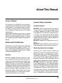
Specifications
Table 1.Overall System
Table 2. EAMPS System
Function Specification
Frequency Range
TX (800MHz)
: 824.04 - 848.97 MHz
Channels 1 to 799, f
TX
= 0.03 * N+ 825MHz
Channels 990 to 1023, f
TX
= 0.03(N-1023)+ 825MHz
RX(800 MHz): 869.04 – 893.97 MHz
Channels 1 to 799, f
RX
= 0.03 * N+ 870MHz
Channels 990 to 1023, f
RX
= 0.03(N-1023)+ 870MHz
TX (1.9 GHz) : 1850.01 – 1909.95 MHz
Channels 1 to 1999 f
TX
= 0.03 * N+ 1849.98MHz
RX (1.9 GHz)
: 1930.05 – 1989.99 MHz
Channels 1 to 1999 f
RX
= TX + 80.04MHz
Channel Spacing 30 kHz
Channels 832 (800MHz), 1999 (1.9 GHz)
Duplex Spacing 45 MHz (800MHz), 80.04 MHz (1.9GHz)
Input/Output Impedance 50 ohms (nominal)
Operating Voltage +3.6 to +4.1Vdc
Dimensions 120cc (Volume)
Weight 140 g
Display 96 X 32 Graphic Matrix
Analog RF Power Output 0.316 Watts (25 dBm)
Digital RF Power Output 0.562 Watts (27.5 dBm)
Automatic Power Control 9, 4 dBm steps
Function Specification
Modulation Type FM
Frequency Stability + 2.5ppm
Duty Cycle Continuous
Audio Distortion
(transmit and receive)
Less than 5% at 1 kHz; + 8 kHz deviation
FM Hum and Noise
(C-MSG weighted)
32 dB below + 8 kHz deviation @ 1 kHz
Voice Modulation Maximum + 12 kHz deviation
Transmit Audio Sensitivity 9 kHz deviation (nom.) @ 97 dB SPL input @ 1 kHz
Receive Sensitivity -116 dBm for 12 dB SINAD (C-MSG weighted)
Adjacent and Alternate
Channel Desensitization
-16 dB @ +30 kHz, -60 dB @ + 60 kHz
IM Greater than 65 dB

©2000 Motorola, Inc.
TDMA T2290/T2297About This Manual
vi
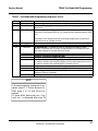
Table 3. DAMPS System
Table 4. Environment
Function Specification
Modulation Type
π/4DQPSK
Frequency Stability + 200 Hz
Duty Cycle 32.3%
Error Vector Magnitude
(π/4DQPSK mode)
Error Vector Magnitude [Digital] 12.5%
Transmit Audio Sensitivity TOLR of –46 dB nominal
Receive Sensitivity -116 dBm for 3% static BER
Adjacent and Alternate
Channel Desensitization
-116 dBm for 3% static BER
IM Less than or equal to 3% static BER
Function Specification
Temperature -30ºC to +60ºC
Humidity 80% RH at 50ºC
Vibration EIA PN1376
Shock EIA PN1376

©2000 Motorola, Inc.
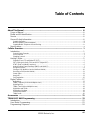
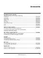
Table of Contents
vii
About This Manual ....................................................................................................................... iii
Scope of Manual ....................................................................................................................... iii
Model and Kit Identification....................................................................................................... iii
Service...................................................................................................................................... iii
General Safety Information ....................................................................................................... iii
Portable Operation........................................................................................................................................ iii
Mobile Operation (Vehicle Adaptor) ............................................................................................................... iii
Portable/Mobile Telephone Use and Driving................................................................................................... iv
Specifications.............................................................................................................................v
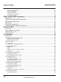
Cellular Overview .......................................................................................................................... 1
Introduction ................................................................................................................................1
Control (Data) Channels ................................................................................................................................2
Voice Channels..............................................................................................................................................3
Signaling Protocol ..........................................................................................................................................3
Analog Cellular...........................................................................................................................5
Signaling Tone (ST) and Digital ST (DST).......................................................................................................5
SAT (Supervisory Audio Tone) and DSAT (Digital SAT) ...................................................................................6
DTMF (Dual Tone Multi-Frequency)................................................................................................................6
Analog Cellular Signal Summary (AMPS and NAMPS) ...................................................................................7
Going into Service .........................................................................................................................................8
Placing a Call (Mobile to Land or Mobile to Mobile) .......................................................................................10
Receiving a Call (Land to Mobile) .................................................................................................................11
Power Steps ................................................................................................................................................13
Hand-offs.....................................................................................................................................................13
Call Termination ...........................................................................................................................................15
Digital Cellular..........................................................................................................................17
Multiplexing .................................................................................................................................................17
FDMA (Frequency Division Multiple Access).................................................................................................17
Digitizing Voice ............................................................................................................................................17
TDMA (Time Division Multiple Access) .........................................................................................................18
Digitization and TDMA .................................................................................................................................18
Digitization of Voltage...................................................................................................................................19
Conventional Radio......................................................................................................................................19
TDMA Radio ................................................................................................................................................20
Accessories ................................................................................................................................. 21
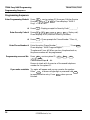
TDMA EASY NAM Programming................................................................................................ 23
Introduction ..............................................................................................................................23
User Mode Programming.........................................................................................................23
Programming Sequence ..........................................................................................................24

©2000 Motorola, Inc.
TDMA T2290/T2297Table of Contents
viii
Enter Programming Mode ............................................................................................................................24
Enter Security Code.....................................................................................................................................24
Enter Phone Number ...................................................................................................................................24
Programming a second No...........................................................................................................................24
If you make a mistake ..................................................................................................................................24
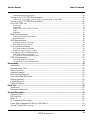
TDMA Test Mode NAM Programming ........................................................................................ 25
Introduction ..............................................................................................................................25
Entering Test Mode NAM Programming...................................................................................25
NAM Programming Steps ........................................................................................................25
NAM Data ................................................................................................................................26
User Mode Programming.........................................................................................................26
Test Mode NAM Programming Sequence................................................................................27
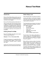
Manual Test Mode........................................................................................................................ 31
Introduction ..............................................................................................................................31
Entering Manual Test Mode .....................................................................................................31
Status Display Level ................................................................................................................31
Servicing Level.........................................................................................................................32
Test Procedures .......................................................................................................................... 35
Introduction ..............................................................................................................................35
Automatic Call-Processing Tests..............................................................................................35
Analog Test Measurements ..........................................................................................................................35
Digital Test Measurements ...........................................................................................................................35
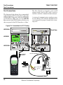
Test Connections .....................................................................................................................36
RF Cable Test ..........................................................................................................................37
To test the RF cable for proper loss: .............................................................................................................37
Set up for Analog call ...............................................................................................................38
Registration .................................................................................................................................................38
Page............................................................................................................................................................38
Select CALL CNTL from the To Screen.........................................................................................................38
Origination ...................................................................................................................................................38
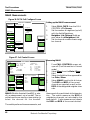
RX Sensitivity Test (SINAD) .....................................................................................................39
Test Mode Commands: ................................................................................................................................39
Communications Analyzer Setup: .................................................................................................................39
TX Power Out Test...................................................................................................................40
Test Mode Commands: ................................................................................................................................40
Communications Analyzer Setup: .................................................................................................................40
Test Mode Commands: ................................................................................................................................41
Communications Analyzer Setup: .................................................................................................................41
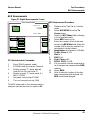
TX Maximum Deviation Test ....................................................................................................42
Test Mode Commands: ................................................................................................................................42
Communications Analyzer Setup: .................................................................................................................42
TX SAT Deviation Test .............................................................................................................43
Procedure....................................................................................................................................................43
Select CALL CNTL from the To Screen.........................................................................................................43
TX ST Deviation Test ...............................................................................................................44
Test Mode Commands: ................................................................................................................................44

©2000 Motorola, Inc.
Table of ContentsService Manual
ix
Communications Analyzer Setup: .................................................................................................................44
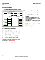
Setting up for PCS TDMA Measurements................................................................................45
Power up the PCS Adapter, after two beeps are heard power up the 8920B.................................................45
Setting up for PCS TDMA Measurements................................................................................46
Set up for TDMA call ................................................................................................................47
Call Process ................................................................................................................................................47
Registration .................................................................................................................................................47
Select CALL CNTL from the To Screen.........................................................................................................47
Page............................................................................................................................................................47
Origination ...................................................................................................................................................47
MAHO Measurements .............................................................................................................48
Setting up the MAHO measurement .............................................................................................................48
Measuring MAHO ........................................................................................................................................48
BER Measurements.................................................................................................................49
PCS Mode Handset Commands:..................................................................................................................49
BER Measurement Procedure......................................................................................................................49
TX Power Measurements ........................................................................................................50
PCS Mode Handset Commands:..................................................................................................................50
Digital TX Power Out Test Procedure ...........................................................................................................50
TX Frequency Error Measurements.........................................................................................51
PCS Mode Handset Commands:..................................................................................................................51
TX Frequency Error Measurement Test ........................................................................................................51
EVM Measurements ...............................................................................................................52
PCS Mode Handset Commands:..................................................................................................................52
TX Frequency Error Measurement Test ........................................................................................................52
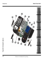
Disassembly ................................................................................................................................ 53
Introduction ..............................................................................................................................53
Recommended Tools ...............................................................................................................53
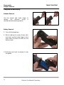
Battery Removal ......................................................................................................................54
Antenna Removal ....................................................................................................................55
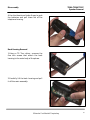
Back Housing Removal............................................................................................................55
Transceiver Board Removal.....................................................................................................56
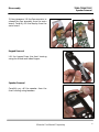
Display Removal ......................................................................................................................56
Keypad Removal......................................................................................................................57
Speaker Removal ....................................................................................................................57
Parts List ...................................................................................................................................... 59
Introduction ..............................................................................................................................59
Mechanical Explosion ..............................................................................................................59
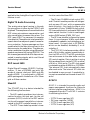
General Description .................................................................................................................... 61
Antenna Circuit ........................................................................................................................61
RX Front End ...........................................................................................................................61
NADC IC ..................................................................................................................................61
TX Operational Description.....................................................................................................62
Power Amp Integrated 800 MHz or 1900 MHz IC ....................................................................62
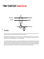
Analog TX Audio Processing ...................................................................................................63

©2000 Motorola, Inc.
TDMA T2290/T2297Table of Contents
x
Digital TX Audio Processing.....................................................................................................63
DSP Lucent 1629.....................................................................................................................63
Stuart IC...................................................................................................................................64
GCAP II....................................................................................................................................64
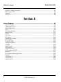
Section B
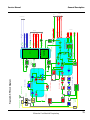
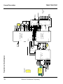
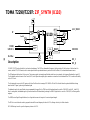
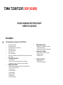
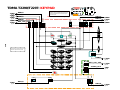
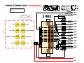
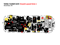
Service Diagrams ....................................................................................................................... B1
Antenna Circuit ....................................................................................................................... B3
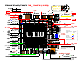
Front End IC(U10)................................................................................................................... B5
ZIFSYNTH(U110).................................................................................................................... B7
VCO ........................................................................................................................................ B9
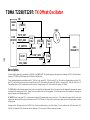
TX Offset Oscillator............................................................................................................... B11
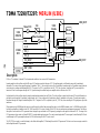
Merlyn(U301) ........................................................................................................................ B13
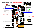
Exciter................................................................................................................................... B15
PA Circuit .............................................................................................................................. B17
RF Detect.............................................................................................................................. B19
Reference Oscillator ............................................................................................................. B21
DCI(U1800)........................................................................................................................... B23
GCAP2(U1500)..................................................................................................................... B25
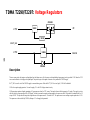
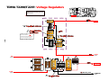
Voltage Regulators................................................................................................................ B27
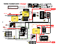
Charger................................................................................................................................. B29
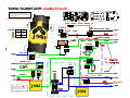
Audio Circuit.......................................................................................................................... B31
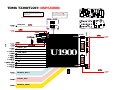
DSP(U1900).......................................................................................................................... B33
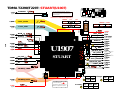
STUART(U1907)................................................................................................................... B35
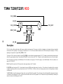
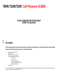
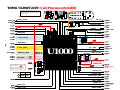
Call Processor(U1000).......................................................................................................... B37
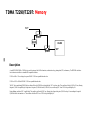
Memory ................................................................................................................................. B39
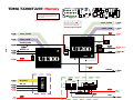
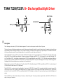
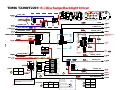
B+ Disconnect/Backlight Driver............................................................................................. B41
Keypad.................................................................................................................................. B43
Connectors............................................................................................................................ B44
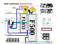
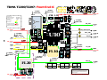
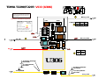
Layout Side 1........................................................................................................................ B45
Layout Side 2........................................................................................................................ B46

©2000 Motorola, Inc.
1
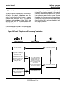
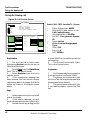
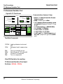
Introduction
A cellular mobile telephone system divides
the service area into small, low power radio
frequency coverage areas called cells. A cel-
lular system consists of a more or less con-
tinuous pattern of these cells, each having a
1 to 40 mile radius (typically 5 - 10 miles).
Within each cell is a centralized cell site with
an elevated antenna and a building. The
building houses a base station with trans-
ceivers and related control equipment for the
channels assigned to that cell. All the cell
sites within a system are then connected ei-
ther by dedicated land lines, microwave links,
or a combination of both to a central control
site called the central controller or switch .
The switch controls the entire cellular sys-
tem and serves as the interface between the
cellular telephone user and the landline net-
work. Each cell site operates on an assigned
access channel, and may have any number
of paging and voice channels assigned to it.
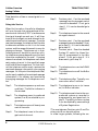
A BAND CHANNELS
Primary Control Channels (21): 313 - 333
Secondary Control Channels (21): 688 - 708
Voice Channels... 001 - 312,
(395 AMPS / 1185 NAMPS): 667 - 716, and
991 - 1023
B BAND CHANNELS
Primary Control Channels (21): 334 - 354
Secondary Control Channels (21): 737 - 757
Voice Channels... 355 - 666 and
(395 AMPS / 1185 NAMPS): 717 - 799
NOTE:
In NAMPS applications, each AMPS voice channel
provides space for three NAMPS voice channels.
Digital cellular multiplexes voice channels to allow for the
possibility of several additional conversations on a single channel.
Figure 1. Channel Assignments
Cellular Overview

©2000 Motorola, Inc.
TDMA T2290/T2297Cellular Overview
2
The cellular radio frequency spectrum has
been divided by the FCC into two equal seg-
ments or bands to allow two independent cel-
lular carriers to coexist and compete in the
same geographic coverage area. Each band
occupies one half of the available channels
in the cellular spectrum. Initially there were
666 channels available across the entire cel-
lular spectrum, but that number was ex-
panded to 832 channels in 1987, and with
NAMPS to 2,412 channels in 1991. Digital
cellular promises to make a further expan-
sion. To guarantee nationwide compatibil-
ity, the signaling channel frequencies have
been pre-assigned to each segment (band).
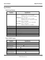
The two bands and their assigned channels
are defined in Figure 1.
Originally the B Band was assigned to the
telephone company (referred to by a euphe-
mism, the Wireline carrier). The A Band, by
default, was referred to as the Non-Wireline
carrier, guaranteed competition to the tele-
phone company. Today the terms Wireline
and Non-Wireline have little meaning since
telephone company carriers now operate A
Band systems, and vice-versa.
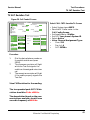
Control (Data) Channels
A cellular telephone in the cellular system is
under the indirect control of the switch, or
central controller. The central controller uses
dedicated control channels to provide the sig-
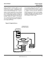
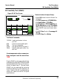
US Cellular Frequency Band
832 channels
001
1023
991 666
667
716
717
799
333
312
313
334
354
355
A' A' B'
Voice
Channels
Voice
Channels
Control
Channels
BB
A A
Band A Band B
A'
666
667
716
717
799
TDMA Secondary
Control Channels
737 - 757688 - 708
Figure 2. US Cellular Frequency Band
Introduction

©2000 Motorola, Inc.
Cellular OverviewService Manual
3
naling required to establish a telephone call.
Control channels are used to send and receive
only digital data between the base station
and the cellular telephone. Voice channels
are used for both audio and signaling once a
call is established. The 21 control channels
in each band may be dedicated according to
two different applications: access and pag-
ing channels.
The data on the forward control channel gen-
erally provides some basic information about
the particular cellular system, such as the
system ID and the range of channels to scan
to find the access and paging channels. Ac-
cess channels are used to respond to a page
or originate a call. The system and the cel-
lular telephone will use access channels
where two-way data transfer occurs to deter-
mine the initial voice channel. Paging chan-
nels, if used, are the normal holding place
for the idle cellular telephone. When a call
is received at the central controller for a cel-
lular telephone, the paging signaling will
occur on a paging channel. In many systems
both control channel functions will be served
by the same control (access) channel for a par-
ticular cell. Only in very high density areas
will multiple control (paging) channels be re-
quired.
Primary control channels are used by all
types of telephones. Secondary control chan-
nels are only used by TDMA telephones, pro-
viding them with an improved probability of
locking onto a TDMA control channel.
Voice Channels
Voice channels are primarily used for con-
versation, with signaling being employed as
necessary to handle cell-to-cell hand-offs,
output power control of the cellular radio-
telephone, and special local control features.
Data from the cell site (known as FORWARD
DATA) and data from the mobile or portable
(known as REVERSE DATA) is sent using
frequency shift keying. In AMPS signaling,
various control and response tones are used
for a variety of applications to be described
later. However, in NAMPS signaling, the sig-
naling data and tones have been replaced by
sub-audible digital equivalents that con-
stantly ride underneath the audio. And, of
course, in digital cellular, all signaling is digi-
tal.
Signaling Protocol
In 1983, when the Federal Communications
Commission (the FCC) licensed cellular te-
lephony, the signaling protocol used was
AMPS. AMPS (Advanced Mobile Phone Ser-
vice) was the invention of Bell Labs, the sig-
naling protocol that was ultimately adopted
by all the governments of the entire Western
Hemisphere and, eventually, several other
governments throughout the world.
Today, with the implementation of Narrow
AMPS and TDMA, and the imminence of
CDMA, it may seem that AMPS is out of date.
The truth is that AMPS is very much alive,
at the very core of all these traffic expanding
alternatives to the original signaling proto-
col developed for conventional cellular tele-
phony.
Under the original AMPS protocol there were
21 control channels assigned to each of two
possible carriers in any metropolitan area,
with a total of 333 channels assigned to each
carrier. Prior to 1987 the FCC had allocated
312 channels to voice (voice, DTMF, or data)
Introduction

©2000 Motorola, Inc.
TDMA T2290/T2297Cellular Overview
4
applications for each carrier. In 1987 the
FCC expanded the cellular spectrum (Ex-
panded Spectrum) from a total of 666 chan-
nels to 832 channels, allowing for an increase
of 83 voice channels for each carrier. But the
number of control channels remained con-
stant, 21 control channels for each carrier.
In 1991, responding to the demand for even
more voice channels, Motorola introduced
NAMPS (Narrow AMPS), expanding the
voice channels by a factor of 3, assuming all
subscribers are using NAMPS telephones.
But one thing remained constant, there were
21 control channels for each carrier.
In 1992, when Motorola tested its TDMA digi-
tal product, digitizing three communication
links on each of 395 voice channels, one thing
remained constant: there were still 21 con-
trol channels for each carrier.
Leaving the control channels more or less un-
touched is the key to allowing telephones that
are not capable of NAMPS or digital opera-
tion to have access to the system using the
conventional AMPS scheme. In virtually
every scheme (AMPS, NAMPS, or digital),
each control channel has a bandwidth of 30
kHz and uses the signaling protocol, with
minor variations for NAMPS and digital,
developed for conventional AMPS
The primary difference between NAMPS and
AMPS is that a NAMPS voice channel has a
bandwidth of only 10 kHz, whereas an AMPS
voice channel has a bandwidth of 30 kHz. In
addition, NAMPS does not make use of cer-
tain control and response tones on voice chan-
nels as does AMPS, but uses digital equiva-
lents instead.
As the name implies, the primary difference
between digital cellular and AMPS is that
all signals are digitized, including voice.
At a basic level, cellular telephony has two
divisions: analog cellular and digital cellu-
lar. In the following section, analog cellular
(AMPS and NAMPS) will be discussed. In
the succeeding section, digital cellular will
be treated.
Introduction

©2000 Motorola, Inc.
Cellular OverviewService Manual
5
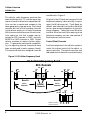
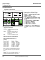
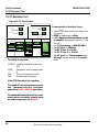
Analog Cellular
The simplified block diagram on page 1 - 7
illustrates an imaginary layout of one side
(Band A, or Band B) of a hypothetical service
area. The hexagons represent cells, and some
of the cell sites shown here also illustrate the
fact that an antenna tower and set of base
stations are associated with each site. In a
real world environment individual cells do
not have the hexagonal shape but may take
any form as dictated by the environment.
The cell sites are in communication with in-
dividual portable and mobile cellular tele-
phones. These portables and mobiles may
move from cell to cell, and as they do they
are “handed off” under the supervision of the
central controller (switch).
As illustrated(figure 3.) by the antenna tower
on the upper left, cell sites transmit overhead
messages more or less continuously even if
there are no mobiles or portables active
within that cell.
The switch (center left) is in control of the
system and interfaces with the central office
of the telephone company. As illustrated by
the deskset telephones, the telephone com-
pany interfaces with the entire landline net-
work.
The cell sites and the mobiles and portables
communicate through the use of data or, in
the case of AMPS, through the use of data
and tones. A complete analysis of data sig-
naling is beyond the scope of this manual.
Refer to the Electronic Industries Association
standard EIA-553 for a thorough discussion
of AMPS signaling protocol, or to Motorola’s
NAMPS Air Interface Specification for
NAMPS.
The tones used in AMPS signaling are Sig-
naling Tones and Supervisory Audio Tones.
NAMPS uses sub-audible digital equivalents.
Signaling Tone (ST) and Digital ST (DST)
In AMPS, signaling tone is a 10 kHz signal
used by the mobile or portable on the reverse
voice channel (REVC) to signal certain ac-
tivities or acknowledge various commands
from the cell site, including hand-offs, alert
orders, and call terminations, and to indicate
switch-hook operation. Various burst lengths
are used for different ST activities. On
NAMPS channels ST is replaced by a digital
equivalent called Digital ST (DST) which is
Cellular
Switch
Telephone
Company
Central Office
Figure 3. Channel Assignments
Analog Cellular

©2000 Motorola, Inc.
TDMA T2290/T2297Cellular Overview
6
the complement of the assigned DSAT.
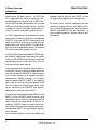
SAT (Supervisory Audio Tone) and DSAT
(Digital SAT)
The Supervisory Audio Tone (SAT) is one of
three frequencies around 6 kHz used in
AMPS signaling. On NAMPS channels SAT
is replaced by one of seven sub-audible digi-
tal equivalents or vectors called DSAT. SAT
(or DSAT) is generated by the cell site,
checked for frequency or accuracy by the cel-
lular telephone, then transponded (that is,
not merely reflected but generated and re-
turned) to the cell site on the reverse voice
channel (REVC). The cellular telephone uses
(D)SAT to verify that it is tuned to the cor-
rect channel after a new voice channel as-
signment. When the central controller
(switch) signals the mobile regarding the new
SAT 0 (5970 Hz)
SAT 1 (6000 Hz)
SAT 2 (6030 Hz)
Cellular System
Re-use
329
332
327
324
333
326
330
318
328
331
324
330
326
320
322
326
319
313
140
119
98
77
56
198
177
156
135
114
143
122
101
80
140
119
98
77
56
voice channel, it also informs the mobile of
the SAT frequency or DSAT vector to expect
on the new channel. The returned (D)SAT
is used at the cell site to verify the presence
of the telephone’s signal on the designated
channel.
In general there are three uses of (D)SAT:
(a) it provides a form of squelch; (b) it pro-
vides for call continuation (but if equipped
for it, the switch will allow for VOX on all
models); and (c) (D)SAT is used to prevent
co-channel interference.
DTMF (Dual Tone Multi-Frequency)
DTMF (Dual Tone Multi-Frequency) touch-
code dialing may also occur on voice chan-
nels. DTMF selects two tones from a total of
nine (cellular only uses seven of these tones /
four low and three high tones) to uniquely
represent individual keys.
Figure 4. Channel Assignments
Table 5. DTMF Values
Analog Cellular
Key Low Tone High Tone
1 697 1209
2 697 1336
3 697 1477
4 770 1209
5 770 1336
6 770 1477
7 852 1209
8 852 1336
9 852 1477
* 941 1209
0 941 1336
# 941 1477

©2000 Motorola, Inc.
Cellular OverviewService Manual
7
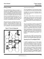
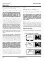
Analog Cellular Signal Summary (AMPS
and NAMPS)
The diagrams on the following pages out-
line the various uses of the signals employed
in cellular systems. These signals include:
SAT (Supervisory Audio Tone) 5970 Hz, 6000
Hz, or 6030 Hz. Used in AMPS for chan-
nel reuse, muting audio (squelch), and call
continuation [typically ± 2 kHz deviation].
Digital SAT (DSAT) - One of seven codes or
vectors used in NAMPS for the same pur-
pose as SAT [± 700 Hz sub-audible NRZ
data].
Data - Transmitted at 10 kilobits/second in
AMPS and 200 bits/second in NAMPS. Data
is used for sending System Orders and Mo-
bile Identification. Do not confuse data with
the 10 kHz signaling tone. In AMPS, data is
transmitted as Manchester-encoded Fre-
quency Shift Keying (FSK), where the car-
rier is shifted high or low 8 kHz, and the trail-
ing edge transition is used to represent the
logic. In NAMPS, data is transmitted as NRZ
(Non-Return to Zero) FSK, where the carrier
is shifted high or low 700 Hz, and the fre-
quency shift itself is used to represent the
logic.
Signaling Tone (ST) - A 10 kHz tone used in
AMPS for mobile ringing, call terminations,
hand-offs, and switch-hook operation [typi-
cally ± 8 kHz deviation]. ST is always ac-
companied by SAT.
Digital ST (DST) - One of seven digital
equivalents of ST used on NAMPS channels.
The transmitted DST is always the comple-
ment of the assigned DSAT [± 700 Hz sub-
audible NRZ data].
Audio - Includes microphone audio and
DTMF [maximum ± 12 kHz deviation AMPS,
± 5 kHz deviation NAMPS]. DTMF devia-
tion should be measured on the radians scale;
use key five looking for 9 radians. Audio is
accompanied by SAT in AMPS signaling.
AMPS Deviation in kHz
AMPS Voice Channels
Control
Channels
Audio
SAT
± 2
± 4
± 6
± 8
±10
±12
±14
Signal
Tone
DataDataAudio
Data
SAT
SAT
Figure 5. AMPS Deviation in kHz
Analog Cellular

©2000 Motorola, Inc.
TDMA T2290/T2297Cellular Overview
8
Total deviation of two or more signals is cu-
mulative.
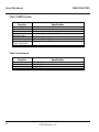
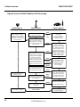
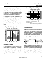
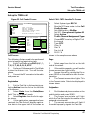
Going into Service
When first turned on, the cellular telephone
will scan through the nationwide set of for-
ward control channels (FOCC’s) and measure
the signal strength on each one. It will then
tune to the strongest one and attempt to de-
code the overhead control message. From the
overhead message, the telephone will be able
to determine whether or not it is in its home
system, and the range of channels to scan for
paging and access. Telephones not in their
home system will be able to use other cellu-
lar telephone systems depending on the level
of service requested by the user. If paging
channels are used, the telephone next scans
each paging channel in the specified range
and tunes to the strongest one. On that chan-
nel the telephone continuously receives the
overhead message information plus paging
messages. At this point the telephone idles,
continuously updating the overhead message
information in its memory and monitoring
the paging messages for its telephone num-
ber.
Step 1. The telephone powers up and runs
a self-test. The NoSvc indicator is
illuminated.
Step 2. The telephone scans its preferred
system (A or B) as selected in pro-
gramming.
Step 3. The telephone scans all twenty-one
control channels.
Step 4. The telephone tunes to the stron-
gest control channel.
Step 5. Decision point. Can the overhead
message from the strongest control
channel be decoded? If not, go to
step 6. If it can be decoded go to
step 8.*
Step 6. The telephone tunes to the second
strongest channel.
Step 7. Decision point. Can the overhead
message stream be decoded? If not,
go to step 12. If it can be decoded,
go to step 8.*
Step 8. Decision point. Does the decoded
System ID match the Home Sys-
tem ID programmed in the tele-
phone? If not, go to step 9. If it
does match, go to step 10.
Step 9. The telephone turns on the ROAM
indicator.
Step 10. The telephone turns off the NoSvc
indicator.
Step 11. The telephone idles. Typically a re-
scan occurs after 5 minutes.
Step 12. The telephone turns on (or leaves
on) its NoSvc indicator.
Step 13. The telephone switches to the non-
preferred system as recorded in
programming, and goes back to
step 3. The ability to return to step
3 can be disabled by some settings
of System Registration.
*The area between Decision point 5 and De-
cision point 8 can be quite active.
In a few larger systems, following the suc-
Analog Cellular

©2000 Motorola, Inc.
Cellular OverviewService Manual
9
cessful completion of either steps 5 or 7, the
telephone scans a set of paging channels,
tunes to the strongest, and attempts to de-
code the overhead message train. The pro-
cedure is exactly equivalent to that followed
for the access (control) channel. Also at this
point, in a few larger systems, the telephone
is commanded to identity itself (transmit) and
thereby indicate its location in the system.
This is called Autonomous System Registra-
tion and, like paging channels, is used to im-
prove paging efficiency.
If the system employs Narrow AMPS, part
of the overhead message stream is used to
ask the for activity on one of the secondary
or “digital” control channels, whereas a
CDMA telephone will look for pilot signals.
If digital signaling is not present, and if the
telephone is capable of dual mode operation,
it will default to AMPS mode.
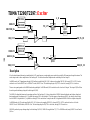
Figure 6. Going into Serivce
Analog Cellular
Yes
1. Power Up / Self Test
Turn on No Svc Indicator
2. Scan Preferred
System (A or B)
3. Scan all 21
Control Channels
4. Tune to Strongest
Control Channel
5.
Receive
Overhead
Info
?
8.
SID matches
Home SID
?
10. Turn Off
NoSvc Indicator
9. Turn on
Roam Indicator
6. Tune to 2nd
Strongest Channel
7.
Receive
Overhead
Info
?
12. Turn On
NoSvc Indicator
13. Switch to
Non-Preferred System
11. Idle [Rescan
after 5 minutes.]
No
No
No*
Yes
Yes
Going Into Service
With a Cellular Telephone
* In those telephones with Motorola Enhanced Scan, more than two control channels are sampled
before proceeding to step 12.
Note: In order to turn on the
Roam light, the SID in the
overhead message stream must
NOT match the SID
programmed into the telephone.
Note: In order to turn off
the NoSvc light, the
overhead message stream
must have been decoded.

©2000 Motorola, Inc.
TDMA T2290/T2297Cellular Overview
10
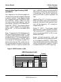
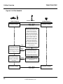
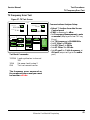
Placing a Call (Mobile to Land or Mobile to
Mobile)
When the cellular telephone user originates
the call, the cellular telephone re-scans
the access channels to assure that it is still
tuned to the strongest one. The cellular tele-
Cellular Telephone Landline NetworkSwitch / Cell Site
DATA
DATA
(D)SAT
(D)SAT
The cellular telephone user
hears the landline ringing.
Conversation in progress
The landline person being
called answers.
Conversation in progress
The cell site receives the
correct SAT or DSAT, then
unmutes the voice path.
FOCC
&
RECC
RECC
The cellular telephone is
tuned to the access / paging
channel, and responds to
requests for data.
The cellular telephone user
dials a telephone number
and presses SND. The tele-
phone rescans the access
channels for the strongest
signal. The telephone
sends out data, including
the dialed digits, MIN, ESN,
and NAMPS or digital
capability to the cell site.
Overhead data is sent out
on the control channels.
FOVC
REVC
The cell site receives the
mobile-to-land call request.
The cell site sends the data to
the switch. The switch
verifies the MIN & ESN and
then sends out the call to the
landline network.
The cellular telephone
receives the voice channel
assignment, drops the
access channel, tunes to the
voice channel, and
transponds the assigned
SAT or DSAT.
DATA
FOCC
The local telephone
company processes the
telephone call.
VOICE + (D)SAT
FOVC & REVC
The switch assigns a voice
channel and SAT or DSAT.
The voice channel assign-
ment is sent to the cellular
telephone on the access
channel. The cell site sends
SAT or DSAT to the cellular
telephone on the assigned
voice channel.
phone then transmits data at the rate of 10
kilobits per second on the control channel to
notify the switch of its mobile identification
number (MIN) and the number it wants to
reach. The switch verifies the incoming data
and assigns a voice channel and a SAT (or
DSAT for NAMPS channels) to the telephone.
Figure 7. Cellular Telephone to Land Call Processing
Analog Cellular
Page is loading ...
Page is loading ...
Page is loading ...
Page is loading ...
Page is loading ...
Page is loading ...
Page is loading ...
Page is loading ...
Page is loading ...
Page is loading ...
Page is loading ...
Page is loading ...
Page is loading ...
Page is loading ...
Page is loading ...
Page is loading ...
Page is loading ...
Page is loading ...
Page is loading ...
Page is loading ...
Page is loading ...
Page is loading ...
Page is loading ...
Page is loading ...
Page is loading ...
Page is loading ...
Page is loading ...
Page is loading ...
Page is loading ...
Page is loading ...
Page is loading ...
Page is loading ...
Page is loading ...
Page is loading ...
Page is loading ...
Page is loading ...
Page is loading ...
Page is loading ...
Page is loading ...
Page is loading ...
Page is loading ...
Page is loading ...
Page is loading ...
Page is loading ...
Page is loading ...
Page is loading ...
Page is loading ...
Page is loading ...
Page is loading ...
Page is loading ...
Page is loading ...
Page is loading ...
Page is loading ...
Page is loading ...
Page is loading ...
Page is loading ...
Page is loading ...
Page is loading ...
Page is loading ...
Page is loading ...
Page is loading ...
Page is loading ...
Page is loading ...
Page is loading ...
Page is loading ...
Page is loading ...
Page is loading ...
Page is loading ...
Page is loading ...
Page is loading ...
Page is loading ...
Page is loading ...
Page is loading ...
Page is loading ...
Page is loading ...
Page is loading ...
Page is loading ...
Page is loading ...
Page is loading ...
Page is loading ...
Page is loading ...
Page is loading ...
Page is loading ...
Page is loading ...
Page is loading ...
Page is loading ...
Page is loading ...
Page is loading ...
Page is loading ...
Page is loading ...
Page is loading ...
Page is loading ...
Page is loading ...
Page is loading ...
Page is loading ...
Page is loading ...
Page is loading ...
Page is loading ...
Page is loading ...
Page is loading ...
Page is loading ...
Page is loading ...
Page is loading ...
Page is loading ...
Page is loading ...
Page is loading ...
Page is loading ...
Page is loading ...
Page is loading ...
-
 1
1
-
 2
2
-
 3
3
-
 4
4
-
 5
5
-
 6
6
-
 7
7
-
 8
8
-
 9
9
-
 10
10
-
 11
11
-
 12
12
-
 13
13
-
 14
14
-
 15
15
-
 16
16
-
 17
17
-
 18
18
-
 19
19
-
 20
20
-
 21
21
-
 22
22
-
 23
23
-
 24
24
-
 25
25
-
 26
26
-
 27
27
-
 28
28
-
 29
29
-
 30
30
-
 31
31
-
 32
32
-
 33
33
-
 34
34
-
 35
35
-
 36
36
-
 37
37
-
 38
38
-
 39
39
-
 40
40
-
 41
41
-
 42
42
-
 43
43
-
 44
44
-
 45
45
-
 46
46
-
 47
47
-
 48
48
-
 49
49
-
 50
50
-
 51
51
-
 52
52
-
 53
53
-
 54
54
-
 55
55
-
 56
56
-
 57
57
-
 58
58
-
 59
59
-
 60
60
-
 61
61
-
 62
62
-
 63
63
-
 64
64
-
 65
65
-
 66
66
-
 67
67
-
 68
68
-
 69
69
-
 70
70
-
 71
71
-
 72
72
-
 73
73
-
 74
74
-
 75
75
-
 76
76
-
 77
77
-
 78
78
-
 79
79
-
 80
80
-
 81
81
-
 82
82
-
 83
83
-
 84
84
-
 85
85
-
 86
86
-
 87
87
-
 88
88
-
 89
89
-
 90
90
-
 91
91
-
 92
92
-
 93
93
-
 94
94
-
 95
95
-
 96
96
-
 97
97
-
 98
98
-
 99
99
-
 100
100
-
 101
101
-
 102
102
-
 103
103
-
 104
104
-
 105
105
-
 106
106
-
 107
107
-
 108
108
-
 109
109
-
 110
110
-
 111
111
-
 112
112
-
 113
113
-
 114
114
-
 115
115
-
 116
116
-
 117
117
-
 118
118
-
 119
119
-
 120
120
-
 121
121
-
 122
122
-
 123
123
-
 124
124
-
 125
125
-
 126
126
-
 127
127
-
 128
128
-
 129
129


Motorola T2290 User manual
- Category
- Two-way radios
- Type
- User manual
- This manual is also suitable for
Ask a question and I''ll find the answer in the document
Finding information in a document is now easier with AI
Related papers
-
Motorola Timeport P8190 User manual
-
-
-
-
-
-
-
-
-
Other documents
-
Agilent Technologies Cell Phone Accessories 8935 series e6380a User manual
-
-
Audiovox BC-20 User manual
-
Merlin IPhone Audio Adapter Quick start guide
-
Ameriphone DIALOGUE VCO User manual
-
-
NEC max 920 User manual
-
Radio Shack 17-1111 User manual
-
HP 83206A User manual
-
Hasbro Stuart Little 2 Stuart Little Operating instructions