D-Link 48-Port 10/100Mbps Web-Smart Switch with 4-Port 10/100/1000Base-T and 2-Port Combo SFP DES-1252 User manual
- Category
- Network switches
- Type
- User manual
This manual is also suitable for

DES-1252
48-Port 10/100Mbps Web-Smart Switch
with 4-Port 10/100/1000Base-T
and 2-Port Combo SFP
User Manual
V1.00

i
i
TABLE OF CONTENTS
About This Guide.................................................................................1
Purpose ............................................................................................1
Terms/Usage....................................................................................1
Introduction..........................................................................................2
Gigabit Ethernet Technology...........................................................2
Fast Ethernet Technology ................................................................3
Switching Technology.....................................................................3
Features............................................................................................4
Technical Specifications..................................................................5
Unpacking and Installation..................................................................9
Unpacking........................................................................................9
Installation .......................................................................................9
Rack Mounting...........................................................................10
Connecting Network Cable........................................................11
AC Power...................................................................................12
Identifying External Components......................................................13
Front Panel.....................................................................................13
Rear Panel......................................................................................14
Understanding LED Indicators ......................................................15
Power and System LEDs ...............................................................15
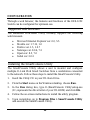
Configuration.....................................................................................19
Supported web browsers................................................................19
Installing the SmartConsole Utility................................................19

i
i
i
i
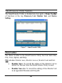
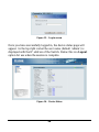
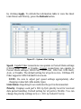
SmartConsole Utility Features.......................................................20
Menu Toolbar.............................................................................20
Discovery List............................................................................22
Monitor List...............................................................................23
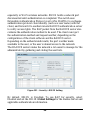
Device Setting............................................................................25
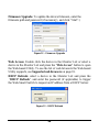
Web-based Utility..........................................................................27
Login..........................................................................................27
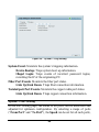
Tool Menu..................................................................................29
Setup Menu....................................................................................30
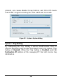
System > System Setting ...........................................................31
System > Trap Setting................................................................32
System > Port Setting.................................................................33
System > SNMP Setting ............................................................35
System > Password Access Control...........................................37
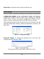
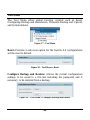
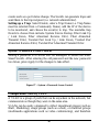
Configuration > 802.1Q VLAN.................................................37
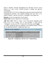
Configuration > Trunking..........................................................40
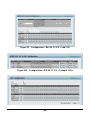
Configuration > IGMP Snooping...............................................41
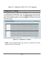
Configuration > 802.1D Spanning Tree.....................................44
Configuration > Port Mirroring..................................................47
QoS > 802.1p Default Priority...................................................48
Security > Safeguard Engine......................................................48
Security > Broadcast Storm Control..........................................49
Security > 802.1X Setting..........................................................49
Security > Mac Address Table > Static MAC............................52
Security > Mac Address Table > Dynamic Forwarding Table ..53

i
i
i
i
i
i
Monitoring > Statistics...............................................................53


1
1
ABOUT THIS GUIDE
Thank you and congratulations on your purchase of the DES-1252 24-
Port 10/100Mbps Fast Ethernet with 4-Port 10/100/1000Base-T and 2-
Port Combo SFP Web-Smart Switch. This device integrates
1000Mbps Gigabit Ethernet, 100Mbps Fast Ethernet and 10Mbps
Ethernet network capabilities in a highly flexible package.
Purpose
This guide will show you how to install and use the configuration
functions of the DES-1252 Web-Smart Switch step-by-step.
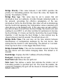
Terms/Usage
In this guide, the term “Switch” (first letter capitalized) refers to the
DES-1252 Smart Switch, and “switch” (first letter lower case) refers
to other Ethernet switches. Some technologies refer to terms “switch”,
“bridge” and “switching hubs” interchangeably, and both are
commonly accepted for Ethernet switches.

2
2
INTRODUCTION
This chapter will describe the features of the DES-1252 and provide
some background information about Ethernet/Fast Ethernet/Gigabit
Ethernet switching technology.
Gigabit Ethernet Technology
Gigabit Ethernet is an extension of IEEE 802.3 Ethernet utilizing the
same packet structure, format, and support for CSMA/CD protocol,
full duplex, and management objects, but with a tenfold increase in
theoretical throughput of over 100-Mbps Fast Ethernet and a
hundredfold increase over 10-Mbps Ethernet. Since it is compatible
with all 10-Mbps and 100-Mbps Ethernet environments, Gigabit
Ethernet provides a straightforward upgrade without wasting existing
investments in hardware, software, or trained personnel.
The increased speed and extra bandwidth offered by Gigabit Ethernet
is essential to help solving network bottlenecks that frequently
develop as more advanced computer users and newer applications
continue to demand greater network resources. Upgrading key
components, such as backbone connections and servers to Gigabit
Ethernet technology can greatly improve network response times as
well as significantly speed up the traffic between subnets.
Gigabit Ethernet enables fast optical fiber connections to support
video conferencing, complex imaging, and similar data-intensive
applications. Likewise, since data transfers occur 10 times faster than
Fast Ethernet, servers outfitted with Gigabit Ethernet NIC’s are able to
perform 10 times the number of operations in the same amount of time.

3
3
In addition, the phenomenal bandwidth delivered by Gigabit Ethernet
is the most cost-effective method to take advantage of today and
tomorrow’s rapidly improving switching and routing internetworking
technologies. And with expected advances in the coming years in
silicon technology and digital signal processing that will enable
Gigabit Ethernet to eventually operate over unshielded twisted-pair
(UTP) cabling, outfitting your network with a powerful 1000-Mbps-
capable backbone/server connection which will create a flexible
foundation for the next generation of network technology products.
Fast Ethernet Technology
The growing importance of LANs and the increasing complexity of
desktop computing applications are fueling the need for high
performance networks. A number of high-speed LAN technologies
have been proposed to provide greater bandwidth and improve
client/server response times. Among them, 100BASE-T (Fast
Ethernet) provides a non-disruptive, smooth evolution from the
current 10BASE-T technology.
100Mbps Fast Ethernet is a standard specified by the IEEE 802.3
LAN committee. It is an extension of the 10Mbps Ethernet standard
with the ability to transmit and receive data at 100Mbps, while
maintaining the CSMA/CD Ethernet protocol. Since the 100Mbps
Fast Ethernet is compatible with all other 10Mbps Ethernet
environments, it provides a straightforward upgrade and utilizes
existing investments in hardware, software, and personnel training.
Switching Technology
Another approach to push beyond the limits of Ethernet technology is
the development of switching technology. A switch bridges Ethernet

4
4
packets at the MAC address level of the Ethernet protocol transmitting
among connected Ethernet or Fast Ethernet LAN segments.
Switching is a cost-effective way of increasing the total network
capacity available to users on a local area network. A switch increases
capacity and decreases network loading by dividing a local area
network into different segments, which won’t compete with each other
for network transmission capacity.
The switch acts as a high-speed selective bridge between the
individual segments. The switch, without interfering with any other
segments, automatically forwards traffic that needs to go from one
segment to another. By doing this the total network capacity is
multiplied, while still maintaining the same network cabling and
adapter cards.
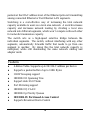
Features
♦ Address Table: Supports up to 8K MAC address per device
♦ Supports a packet buffer of up to 128K Bytes
♦ IGMP Snooping support
♦ IEEE802.1D Spanning Tree
♦ Support static Port Trunk
♦ Port Mirroring support
♦ IEEE802.1Q VLAN
♦ IEEE802.1p Priority Queues
♦ IEEE802.1X Port-based Access Control
♦ Supports Broadcast Storm Control

5
5
♦ Supports Static MAC setting
♦ D-Link Safeguard Engine support
♦ Supports Simple Network Management Protocol(SNMP)
♦ MIB support for: RFC1213 MIB II, Private MIB
♦ Supports DHCP client
♦ Supports Port setting for Speed, Duplex Mode
♦ Easy configuration via Web Browser
♦ Easy setting via SmartConsole Utility
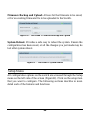
♦ Firmware backup and upload via Web GUI
♦ System reboot via Web GUI
♦ Provides parallel LED display for port status such as link/act,
speed, etc.
♦ Reset configuration (hardware and Web GUI)
Technical Specifications
Key Components / Performance
Switching Capacity
17.6Gbps
Max. Forwarding Rate
10M: 14,880 pps
100M: 148,809 pps
1G: 1,488,095 pps
Forwarding Mode
Store and Forward
Packet Buffer memory
128K Bytes

6
6
SDRAM for CPU
8M Bytes
Flash Memory
Prom 2M Bytes
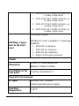
Port Functions
LAN
- 48 x 10/100BaseT ports
- Compliant with the following standards:
1. IEEE 802.3 compliance
2. IEEE 802.3u compliance
3. Support Full and Half Duplex operations
Combo ports in the
front panel
- 2 Combo 1000Base-T/SFP ports
-1000Base-T/SFP ports compliant to the
following standards:
1. IEEE 802.3 compliance
2. IEEE 802.3u compliance
3. IEEE 802.3ab compliance
4. Support Full-Duplex operations
- SFP Transceivers Supported:
1. DEM-310GT (1000BASE-LX)
2. DEM-311GT (1000BASE-SX)
3. DEM-314GT (1000BASE-LH)
4. DEM-315GT (1000BASE-ZX)
5. DEM-312GT2 (1000BASE-SX), up to
2km
6. DEM-211 (100BASE-FX), up to 2km,
Multi-Mode
7. DEM-210 (100BASE-FX), up to 15km,
Single-Mode
-WDM Transceivers Supported:

7
7
1. DEM-330T (TX-1550/RX-1310nm), up
to 10km, Single-Mode
2. DEM-330R (TX-1310/RX-1550nm), up
to 10km, Single-Mode
3. DEM-331T (TX-1550/RX-1310nm), up
to 40km, Single-Mode
4. DEM-331R (TX-1310/RX-1550nm), up
to 40km, Single-Mode
1000Mbps Copper
ports in the front
panel
2 1000Base-T ports
1000Base-T ports compliant to following
standards:
1. IEEE 802.3 compliance
2. IEEE 802.3u compliance
3. IEEE 802.3ab compliance
4. Support Full-Duplex operations
Chassis
Dimensions
19-inch, 1U Rack-mount size
440mm x 310mm x 44mm
Reset button on the
front panel
A factory reset button x 1
Physical & Environment
AC input
100~240 VAC, 50/60Hz
Internal universal power supply
Operation
Temperature
0~40°C

8
8
Storage Temperature
-10~70°C
Humidity
Operation: 10%~90% RH
Storage: 5%~90% RH
Power consumption
26.6(watts)
Heat Dissipation
86.95(btu/hr)
MTBF
298917 (hours)
Emission (EMI) and Safety Certifications
EMI-EMC Compliance: FCC class A, CE Class A, VCCI Class A
Safety Compliance: cUL, UL

9
9
UNPACKING AND INSTALLATION
This chapter provides unpacking and installation information for the
Web-Smart Switch.
Unpacking
Carefully unpack the contents of the Web-Smart Switch from the box
and locate the following items:
One DES-1252 Web-Smart Switch
One AC power cord, suitable for the local electrical power voltage
requirements
Four rubber feet to be used for shock cushioning
Screws and two mounting brackets
CD-Rom with the SmartConsole Utility application, which includes
the full User’s Guide
Quick Installation Guide
If any item is found missing or damaged, please contact the reseller
for replacement.
Installation
The site chosen for installation greatly affects the Web-Smart
Switch’s performance. When installing, consider the following points:
Install the Switch in a fairly cool and dry place. See Technical
Specifications for the acceptable temperature and humidity
operating ranges.

1
1
0
0
Install the Switch in a site free from strong electromagnetic field
generators (such as motors), vibration, dust, and direct exposure to
sunlight.
Leave at least 10cm of space to the front and rear of the Switch for
ventilation.
Install the Switch on a sturdy, level surface that can support its
weight, or in an EIA standard-size equipment rack. For information
on rack installation, see the next section, Rack Mounting.
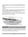
When installing the Switch on a level surface, attach the rubber
pads (feet) to the bottom. The rubber feet cushion the switch and
helps protect the case from scratches.
Figure 1 – Attach the adhesive rubber pads to the bottom
Rack Mounting
The Switch can be mounted in an EIA standard-size, 19-inch rack or
chassis, which can be placed in a wiring closet with other equipment.
Attach the mounting brackets to both sides of the Switch (one on each
side), and secure them with the provided screws.

1
1
1
1
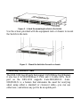
Figure 2 – Attach the mounting brackets to the Switch
Use the screws provided with the equipment rack or chassis to mount
the Switch in the rack.
Figure 3 – Mount the Switch in the rack or chassis
Connecting Network Cable
The DES-1252 has 48 ports that support 10/100Mbps Fast Ethernet;
it also has 4 10/100/1000Base-T Ports and 2 Combo SFPs. Each
port on the DES-1252 supports Auto-MDI/MDI-X. Auto-
MDI/MDI-X is a feature that eliminates the need for worrying
about using either a standard or crossover cable—you can use
either one—and allows any port to be an uplink port.

1
1
2
2
AC Power
The DES-1252 can be used with AC power supply 100~240V AC,
50~60Hz. The power switch is located at the rear of the unit adjacent
to the AC power connector and the system fan.
The switch’s power supply will adjust to the local power source
automatically and may be turned on without having any or all LAN
segment cables connected.

1
1
3
3
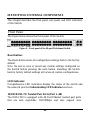
IDENTIFYING EXTERNAL COMPONENTS
This chapter describes the front panel, rear panel, and LED indicators
of the Switch.
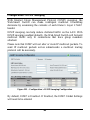
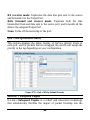
Front Panel
The figure below shows the front panel of the Switch.
Figure 4 – Front panel of the 28-port Web-Smart Switch
Reset button:
The Reset button resets all configuration settings back to the factory
default.
Note: Be sure to save or record any custom settings configured on
the Switch before pressing the reset button. Resetting the Switch
back to factory default settings will erase all custom configurations.
LED Indicator:
Comprehensive LED indicators display the status of the switch and
the network (see the Understanding LED Indicators section).
10/100 BASE-TX Twisted Pair Ports (Port 1~48)
The DES-1252 is equipped with 48 Fast Ethernet twisted pair ports
that are auto negotiable 10/100Mbps and also support auto

1
1
4
4
MDI/MDIX crossover detection. All these 48 ports can operate in
half- and full- duplex modes.
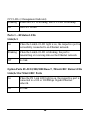
10/100/1000 BASE-T / Mini GBIC Combo Ports (Option Port
49~50)
The Switch is also equipped with two combo 10/100/1000 Base-T /
Mini GBIC ports, which supports optional 100 or 1000BASE-SX/LX
and 100Base-FX Mini GBIC module for fiber uplinks.
10/100/1000 BASE-T Twisted Pair Ports (Port 51~52)
Finally there are 2 Gigabit twisted pair ports that are auto negotiable
10/100/1000Mbps with auto MDI/MDIX crossover detection support
that can also operate in half- and full- duplex modes.
Note: When a port is set to “Forced Mode”, the Auto MDI/MDIX
will be disabled.
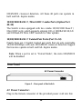
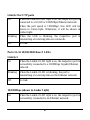
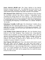
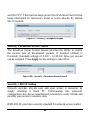
Rear Panel
Figure 5 – Rear panel of the Switch
AC Power Connector:
Plug in the female connector of the provided power cord into this
A
C Power Connector

1
1
5
5
connector, and the male into a power outlet. Supported input
voltages range from 100-240V AC, and 50-60Hz.
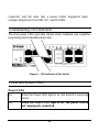
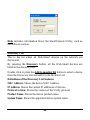
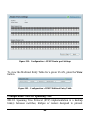
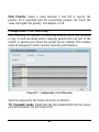
Understanding LED Indicators
The front panel LEDs provides instant status feedback and simplifies
monitoring and troubleshooting tasks.
Figure 6 – LED indicators of the Switch
Power and System LEDs
Power LEDs
On When the Power LED light is on, the Switch is receiving
power.
Off
When the Power LED light is off, the power cord is
not improperly connected.
Page is loading ...
Page is loading ...
Page is loading ...
Page is loading ...
Page is loading ...
Page is loading ...
Page is loading ...
Page is loading ...
Page is loading ...
Page is loading ...
Page is loading ...
Page is loading ...
Page is loading ...
Page is loading ...
Page is loading ...
Page is loading ...
Page is loading ...
Page is loading ...
Page is loading ...
Page is loading ...
Page is loading ...
Page is loading ...
Page is loading ...
Page is loading ...
Page is loading ...
Page is loading ...
Page is loading ...
Page is loading ...
Page is loading ...
Page is loading ...
Page is loading ...
Page is loading ...
Page is loading ...
Page is loading ...
Page is loading ...
Page is loading ...
Page is loading ...
Page is loading ...
Page is loading ...
Page is loading ...
-
 1
1
-
 2
2
-
 3
3
-
 4
4
-
 5
5
-
 6
6
-
 7
7
-
 8
8
-
 9
9
-
 10
10
-
 11
11
-
 12
12
-
 13
13
-
 14
14
-
 15
15
-
 16
16
-
 17
17
-
 18
18
-
 19
19
-
 20
20
-
 21
21
-
 22
22
-
 23
23
-
 24
24
-
 25
25
-
 26
26
-
 27
27
-
 28
28
-
 29
29
-
 30
30
-
 31
31
-
 32
32
-
 33
33
-
 34
34
-
 35
35
-
 36
36
-
 37
37
-
 38
38
-
 39
39
-
 40
40
-
 41
41
-
 42
42
-
 43
43
-
 44
44
-
 45
45
-
 46
46
-
 47
47
-
 48
48
-
 49
49
-
 50
50
-
 51
51
-
 52
52
-
 53
53
-
 54
54
-
 55
55
-
 56
56
-
 57
57
-
 58
58
-
 59
59
-
 60
60


D-Link 48-Port 10/100Mbps Web-Smart Switch with 4-Port 10/100/1000Base-T and 2-Port Combo SFP DES-1252 User manual
- Category
- Network switches
- Type
- User manual
- This manual is also suitable for
Ask a question and I''ll find the answer in the document
Finding information in a document is now easier with AI
Related papers
-
D-Link DES-1250G User manual
-
-
-
D-Link DES-1210-28/52 User manual
-
-
-
Dlink DGS-1216T Owner's manual
-
D-Link EasySmart User manual
-
-
D-Link DGS-1100-08P User manual
Other documents
-
Trendnet TE100-S24WS Owner's manual
-
 Planex SW-2248F User manual
-
Comet Labs GSM2400R Owner's manual
-
Allnet ALL4706W User manual
-
Allnet ALL4704W User guide
-
Trendnet TEG-224WS Owner's manual
-
 MicroNet Technology SP648B User manual
-
-
Trendnet TEG-240WS User guide
-
Trendnet TEG-224WSPLUS User manual

