Page is loading ...

INSTRUCTION BOOK
TAMD162C, TAMD163A, TAMD163P


1
CALIFORNIA
Proposition 65 Warning
Diesel engine exhaust and some of its consistituents are known to
the state of California to cuse cancer, birth defects, and other
reproductive harm.
Contents
Safety information .................................................... 2
Introduction............................................................... 2
Important................................................................... 2
General information .................................................. 4
Running-in ................................................................. 4
Fuel and lubricants ................................................... 4
Spare parts ............................................................... 4
Safety ....................................................................... 4
Warranty and guarantee ........................................... 5
Warranty Registration Card ...................................... 5
Maintenance ............................................................. 5
Certificated engines.................................................. 6
Introduction............................................................... 7
The engines .............................................................. 7
Instrumentation......................................................... 10
Instrument panels..................................................... 10
Instrument kits ......................................................... 12
Controls..................................................................... 13
Key switch ................................................................ 13
Fuel, lubricating oils, engine coolant ....................... 16
Operation .................................................................. 17
Before starting .......................................................... 17
Starting the engine ................................................... 19
Starting using auxiliary batteries ............................. 20
Checks during operation .......................................... 21
Maneuvering during operation .................................. 21
After operation .......................................................... 23
Propeller shaft brake ................................................ 23
When there is a danger of freezing.......................... 24
Mechanical safety clutch ......................................... 25
Maintenance ............................................................. 28
Periodic maintenance............................................... 29
Maintenance schedule ............................................. 30
Technical description ............................................... 36
Engine....................................................................... 36
Maintenance, Engine................................................ 40
Lubrication system ................................................... 42
Maintenance, Lubrication systems.......................... 44
Fuel system.............................................................. 47
Maintenance, Fuel system....................................... 50
Cooling system......................................................... 52
Maintenance. Cooling system ................................. 55
Electrical system...................................................... 58
Electrolytic corrosion................................................ 60
Electrical system – Important.................................. 61
Maintenance. Electrical system .............................. 62
Wiring diagrams........................................................ 63
Inhibiting ................................................................... 70
Launching procedures .............................................. 70
Troubleshooting ........................................................ 71
Technical data .......................................................... 74

2
Safety Precautions
Immobilize the engine by turning off the power
supply to the engine at the main switches (break-
ers) so it is impossible to start, and lock the
switches (breakers) in the OFF position before
starting work. Set up a warning notice at the
engine control point or helm.
Never start the engine without installing the air
cleaner (ACL) filter. The rotating compressor in
the Turbo can cause serious personal injury.
Foreign objects entering the intake ducts can also
cause mechanical damage.
Never use start spray or similar agent to start the
engine, it could cause an explosion in the inlet
manifold. Danger of personal injury.
Steam or hot coolant can be ejected and the
pressure built up will be lost. Steam or hot coolant
can spray out and the system pressure will be
lost. Open the filler cap slowly and release
coolant system pressure, if the filler cap or a drain
cock/venting cock must be opened, or if a plug or
engine coolant line must be removed on a hot
engine. Steam or hot coolant can spray out.
Stop the engine and close the seacock valve
before carrying out operations on the engine
cooling system.
Only start the engine in a well-ventilated area. If
operating the engine in a closed area ensure that
there is exhaust ventilation leading out of the
work area to remove exhaust gases and crank-
case ventilation emissions.
Anti-corrosion agents are hazardous to health.
Read the instructions on the product packaging!
Anti-freeze agents are hazardous to health. Read
the instructions on the product packaging!
Certain engine conservation oils are inflammable.
Some of them are also dangerous if breathed in.
Ensure good ventilation in the work place. Use a
protective mask when spraying.
Hot oil can cause burns. Avoid getting hot oil on
the skin. Ensure that the lubrication system is not
under pressure before carrying out any work.
Never start or operate the engine with the oil filler
cap removed, otherwise oil could be ejected.
Introduction
This Instruction Book contains the information you will
need to operate the engine correctly. Check that you
have the correct Instruction Book for your engine.
Read the book carefully before operating or servic-
ing the engine. If operations are performed incorrectly
it could result in personal injury, or damage to property
or the engine.
If you do not understand or are uncertain about
any opertion or information in this manual, please
contact your Volvo Penta dealer who will be able to
assist with an explanation and demonstration of
the operation.
Important
In this book and on the engine you will find the following
special warning symbols.
WARNING! Possible danger of personal injury,
damage to property or mechanical malfunction if
the instructions are not followed.
Read the Instruction Book.
Below is a summary of the risks and safety precautions
you should always observe or carry out when operating
or servicing the engine.
Check that the warning or information labels on
the engine are always clearly visible. Replace
labels which have been damaged or painted over.
Always turn the engine off before starting service
procedures. Avoid burns. Take precautions to
avoid hot surfaces and liquids in supply lines and
hoses when the engine has been turned off
immediately prior to starting work on it and it is
still hot.
Reinstall all protective parts removed during
service operations before starting the engine.
Make a point of familiarizing yourself with other
risk factors, such as rotating parts and hot surfac-
es (exhaust manifold, turbocharger, charge pipe,
starter element, charge air cooler, intake pipe
etc.).
Approaching an engine which is operating is a
safety risk. Loose clothing or long hair can fasten
in rotating parts and cause serious personal
injury.
If the service operation requires that the engine is
operating let your Penta authorized dealer carry
out the work. If working in proximity of an engine
which is operating, careless movements or a
dropped tool can result in personal injury.

3
Never allow an open flame or electric sparks near
the batteries. Never smoke in proximity to the
batteries. The batteries give off hydrogen gas
during charging which when mixed with air can
form an explosive gas -oxyhydrogen. This gas is
easily ignited and highly volatile. Incorrect con-
nection of the battery can cause a single spark
which is sufficient to cause an explosion with
resulting damage. Do not shift the connections
when attempting to start the engine (spark risk)
and do not lean over any of the batteries. Refer to
instructions in the Instruction Book.
Always ensure that the Plus (positive) and Minus
(negative) battery leads are correctly installed on
the corresponding terminal posts on the batteries.
Incorrect installation can result in serious damage
to the electrical equipment. Refer to the wiring
diagrams.
Always use protective goggles when charging and
handling the batteries. Battery electrolyte contains
sulfuric acid which is highly corrosive. Should the
battery electrolyte come into contact with unpro-
tected skin wash off immediately using plenty of
water and soap. If battery acid comes in contact
with the eyes, immediately flush with plenty of
water and obtain medical assistance without
delay.
Turn the engine off and turn off the power at the
main switches (breakers) before carrying out work
on the electrical system.
Clutch adjustments, where a clutch is fitted, must
be carried out with the engine turned off.
Use the lifting eyes fitted on the engine/reverse
gear when lifting the drive unit. Always check that
the lifting equipment used is in good condition and
has the load capacity to lift the engine (engine
weight including reverse gear and any extra
equipment installed).
Use a lifting beam to raise the engine to ensure
safe handling and to avoid damaging engine parts
installed on the top of the engine.
All chains and cables should run parallel to each
other and as perpendicular as possible against
the side of the engine.
If extra equipment is installed on the engine which
alters its center of gravity a special lifting device is
required to obtain the correct balance for safe
handling.
Never carry out work on an engine suspended on
a hoist.
WARNING! The components in the electrical
system and in the fuel system on Volvo Penta
products are designed and manufactured to
minimize risks of fire and explosion.
The engine must not be run in areas where there
are explosive materials.
Fuel filter replacement should be carried out on a
cold engine in order to avoid the risk of fire
caused by fuel spillage on the exhaust manifold.
Always cover the generator (alternator), if it is
located under the fuel filter. The generator
(alternator) can be damaged by spilled fuel.
WARNING! The delivery pipes must not be bent,
twisted or subjected to other stress. Replace
damaged delivery pipes.
Always use protective gloves when detecting
leaks. Liquids ejected under pressure can pene-
trate the body tissues and cause serious injury.
Danger of blood poisoning.
Always use fuels recommended by Volvo Penta.
Refer to the Instruction manual. Use of fuels that
are of a lower quality can damage the engine. On
a diesel engine poor quality fuel can cause the
actuating rod to seize and the engine to overrev
with resulting risk of damage to the engine and
personal injury. Poor fuel quality can also lead to
higher maintenance costs.
Observe the following when cleaning with high-
pressure water jets. Never point the water jet at
seals, rubber hoses or electrical components.
Never use high pressure jets when washing the
engine.

4
General Information
The oil and oil filter* in the Twin Disc reverse gear
should first be changed at this point too. Remove and
clean the reverse gear’s oil screen at the same time. In
the case of MPM reverse gears, the oil screen should
be cleaned after 10 and 50 hours of operation, and the
first oil and filter change* should be made after 50 hours
of operation.
The disengageable clutch should be checked more
closely during the first few days. It may be necessary to
adjust it to compensate for wear to the laminate.
*Only the TD MG516, and MPM IRM 350 have oil filters.
Fuel and lubricants
Only use lubricants and fuels recommended on page 16
or under “Technical Data”. Use of other qualities can
cause malfunctions and reduced service life.
Spare parts
Warning! The components in the electrical
system and in the fuel system on Volvo Penta
products are designed and manufactured to
minimize risks of fire and explosion.
Using parts that are not Original Volvo Penta
parts which do not correspond to the demands
above, can result in fire or explosion on board.
Any type of damage which is the result of using
replacement parts that are not original Volvo
Penta replacement parts for the product in
question will not be covered under any warranty
or guarantee provided by AB Volvo Penta.
Safety
Everyone wants and expects to have a problem-free
and pleasant time when they take their boat out. To
help you do this we have provided a pre-journey check-
list below, which can of course be added to according
personal experience. A major area is naturally the
engine, its equipment and that the boat in general is
properly maintained.
Planning your trip
– Get out up-to-date charts for the route planned.
– Calculate distance and fuel consumption.
– Note down if there are fuel points on your planned
course.
– Tell friends or relatives about your trip plans.
Welcome aboard
Thank you for choosing a Volvo Penta marine engine.
Volvo Penta have been building marine engines since
1907. Quality, operating reliability and innovation have
made Volvo Penta a world leader in the marine engine
industry.
As owner of a Volvo Penta marine engine we would
also like to welcome you to a worldwide network of
dealers and service workshops to assist you with
technical advice, service requirements and replacement
parts. Please contact your nearest authorized Volvo
Penta dealer for assistance.
We would like to wish you many pleasant voyages.
AB VOLVO PENTA
Technical Information
Your new boat
Every new boat has it own special characteristics. Even
experienced boat owners are advised to note carefully
how the boat behaves at different speeds, weather
conditions and loads. If your boat and engine combina-
tion permit high-speed use, we strongly recommend
that a safety breaker is fitted, regardless of the type of
boat. If your boat is not fitted with a safety breaker
contact your Volvo Penta dealer who can assist you in
selecting one.
Running-in
When the engine is new, it should be run normally.
However, full loading should be avoided for more than
brief periods during the first ten hours of use. Unneces-
sary idling of an unloaded engine should always be
avoided.
Check the instrumentation extra carefully during this
period so that any abnormal conditions may be discov-
ered in good time.
Check also that there are no leaks.
With a new or reconditioned engine, the valve
clearance should first be checked after 150 hours of
operation.

5
Boat equipment
– Rescue and emergency items such as lifevests and
signal rockets. Does everyone know where they
are?
– Spare parts on board, for example Kit with water
pump impeller etc.
– Proper tools for the equipment.
– Fire extinguisher (checked and charged).
Warranty and guarantee
A Service and Warranty book with conditions for Volvo
Penta’s International Limited Warranty is supplied with
every engine. Contact your nearest Volvo Penta dealer
or importer for your copy if you have not received one.
Some markets can have other warranty conditions
depending on national legislation and regulations.
These conditions are provided by the Volvo Penta
importer or distributor for the market in question. If you
wish to have a copy of the conditions please contact
your local Volvo Penta representative.
Warranty Registration Card
The Warranty Registration Form (North American
market) or Warranty Card (other markets) should
always be filled out and sent in by the dealer. Make
sure that this has been done, if no proof of the delivery
date can be provided the warranty undertakings might
not be honored.
Maintenance and care
– PDC (Pre-Delivery Commissioning) delivery under-
taking for marine engines: “PDC” enables us to
ensure that Volvo Penta products operate correctly
after installation in a boat, and further that the end-
user gets acquainted with the product, its functions
and care (refer to checklist in the Warranty and
Service book). Delivery undertaking “PDC” is carried
out at the time of the delivery of the boat to the end-
user. The cost of this work is covered by the Volvo
Penta company’s International Limited Warranty.
– First Service inspection: A First Service inspection
must be carried out after 150–300 running hours or
within 180 days of delivery, or at the end of the first
season, whichever comes first. Labor and material
costs in connection with the First Service Inspection
are not covered by the Volvo Penta International
Limited Guarantee (for checklist see your Warranty
and Service book).
Regular maintenance should be carried out after the
First Service Inspection in accordance with the mainte-
nance scheme in this book. Any work carried out in
addition to maintenance services should be document-
ed (refer to the Warranty and Service book).
It is an absolute condition for the Volvo Penta Interna-
tional Limited Warranty to apply that the Pre-Delivery
Commissioning and First Service Inspection have been
carried out by an authorized Volvo Penta service dealer.
Our joint responsibility
Volvo Penta continually commits a considerable part of
its development resources towards minimizing the
environmental impact of its products. Examples of areas
where we are always looking for improvements are
exhaust emissions, noise levels and fuel consumption.
Regardless of whether your Volvo Penta engine is
installed in a boat used for pleasure or in commercial
operation, incorrect operation or improper maintenance
of the engine will result in disturbance or damage to the
environment.
In this instruction book there are a number of service
procedures, which, if not followed will lead to a deterio-
ration of engine characteristics with regard to how it
effects the environment, its service life and cost of
operation. Always follow the recommended service
intervals and make a habit of checking that the engine
is operating normally every time you use it. One exam-
ple is excessively smoky exhaust. Contact an author-
ized Volvo Penta workshop if you cannot correct the
fault yourself.
Bear in mind that most of the chemicals used around
boats are harmful to the environment if used incorrectly.
Volvo Penta recommends the use of bio-degradable
degreasing agents for all cleaning. Always dispose of
engine and transmission oil waste, old paint, degreasing
agents and cleaning residue etc. at proper disposal
areas so they do not harm the environment.
Adapt speed and distance during your boat trips so that
swell and noise generated by the boat do not disturb or
harm wildlife, moored boats, landing stages etc. Wher-
ever you land or cruise, please show consideration and
always leave the areas you visit as you would like to
find them yourself.

6
Volvo Penta Service
Volvo Penta has a comprehensive dealer network that
offers both service and spare parts for Volvo Penta
engines. These dealers have been carefully selected
and trained to provide professional assistance for
service and repairs. They also have the special tools
and testing equipment required for maintaining a high
standard of service. Volvo Penta dealers and vendors
must maintain a stock of original spare parts and
accessories to cover most requirements of Volvo Penta
owners.
When ordering a service or spare parts always quote
the engine and drive/reverse gear complete type
designation and serial number. You will find this infor-
mation on the engine product plate and on a label on
the front valve cover (see page 7).
Certificated engines
Important information for engines certificated for
Lake Constance and Switzerland
All Volvo Penta engines and products are developed to
minimize environmental impact.
National and regional legislation is not identical in all the
markets where Volvo Penta sells its products. Occa-
sionally legislation requires that we build special engine
variants, or that an engine must be approved in ad-
vance, that is, certificated by the local authorities.
An engine with certification means that we, as the
manufacturer, guarantee that all engines manufactured
are of the same type as the certificated and approved
example. Certification is not only a requirement cover-
ing engines from the factory, but also that engines in
use must meet the environmental demands set for that
engine. In order for Volvo Penta as the manufacturer to
take responsibility for engines in use, certain require-
ments pertaining to service and spare parts must be
met. We do not wish to discourage owners from carry-
ing out service work themselves, rather the opposite
since an owner can quickly notice if an engine is not
operating normally.
However, a number of service operations demand
access to special expertise, workshop manuals, special
tools and other equipment designed for the engines.
These service operations may only be carried out by an
authorized Volvo Penta Service workshop. Always
contact your Volvo Penta dealer if you are not sure
about anything concerning your engine’s function or
maintenance.
As an owner or operator of a certificated Volvo Penta
engine it is important that you are aware of the follow-
ing:
● The Service Intervals and maintenance operations
recommended by Volvo Penta must be followed.
● Only Volvo Penta Original Spare parts intended for
the certificated engine may be used.
● Service work on the injection pump and injectors or
pump settings must always be carried out by an
authorized Volvo Penta workshop.
● The engine may not be altered or modified in any
way, with the exception of accessories and service
kits developed by Volvo Penta for that engine.
● No modifications to the exhaust pipes and air supply
ducts for the engine room (ventilation ducts) may be
undertaken as this may effect exhaust emissions.
● Any seals on the engine may not be broken other
than by authorized persons.
Important! If spare parts are required use only
Volvo Penta Original parts.
Use of spare parts other than AB Volvo Penta
Original spare parts will result in AB Volvo
Penta cannot assume any liability for the
engine meeting requirements under the
engine certification. Any type of damage which
is the result of using replacement parts that are
not original Volvo Penta replacement parts for the
product in question will not be covered under any
warranty or guarantee provided by AB Volvo
Penta.
Identifying Numbers
Immediately after you have taken delivery of your boat,
make a note of the serial number and model designa-
tion of the engine and reverse gear. Include the serial
number and model designation of the boat and any
extra equipment. This information is necessary when
you contact your Volvo Penta or boat sales representa-
tive for service and spare parts. Take a copy of the
information. Take a copy of the information and keep it
in a safe place so it is available should the boat be
stolen.
Engine type ....................................................................
Serial No. .......................................................................
Reverse gear type..........................................................
Serial No. .......................................................................
Propeller designation .....................................................
Boat type ........................................................................
Serial No. .......................................................................
Other equipment ............................................................
Serial No. .......................................................................
© 1998 AB VOLVO PENTA
All rights to changes or modifications reserved.
Printed on environmentally-friendly paper

7
Introduction
The engines
TAMD162C, TAMP163A, TAMD163P-A
The basic engine is an in-line six cylinder, water-cooled diesel engine with direct fuel injection and piston cooling. It
has a displacement of 16 liters.
The engine uses a seawater cooled charge air cooler (CAC). The CAC reduces the temperature of the intake air to
the engine after it has been compressed in the turbocharger. This permits a high power output while keeping the
combustion and exhaust gas temperatures to appropriate levels.
The engine has separate cylinder heads, one for each cylinder. There are four valves per cylinder head, two inlet and
two exhaust. The pistons are cooled by lubricant oil via special jets in the engine block. The cylinder liners are of the
wet type and are replaceable.
The cooling system is thermostatically controlled. Freshwater in the engine is cooled by seawater in a heat ex-
changer.*
For a more detailed description of the engine, its fuel, lubrication, and cooling systems, etc., see under “Technical
Specification” on pages 36–62.
* Note: TAMD162C and TAMD163A can also be delivered for connection to keel cooling systems.
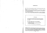
Reverse gear design.
Serial number
Product No.
Certification plate (TAMD163P)
Approval No. (Certifying)
EMISSION APPROVED IN ACCORDANCE TO THE
BODENSEE SCHIFFAHRTS ORDNUNG ANLAGE C.
APPROVAL NO:
xxxxxxxxxx
ENGINE
TAMD162C
XXXXXXXXXX
868416
Engine designation
Serial No.
Product No.
TD MG516
XXXXXXXXXX
3825410
Engine designation Product number
Serial No. Basic engine number
TAMD162C 868416
N
o
. xxxxxxxxxx / xxxxx

8
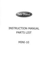
12 3 4 5 6 78
15 14 13 12 11 10 9
Fig. 1. TAMD162C from starboard
(classifiable version).
1. Air cleaner (ACL)
2. Freshwater system bleed tap
3. Emergency start button
4. Stop solenoid
5. Injection pump
6. Intake manifold with charge air cooler (CAC)
7. Fine fuel filters
8. Coolant filler cap
9. Expansion tank
10. Heat exchanger
11. Seawater pump
12. Flushing pump
13. Bilge pump
14. Fuel feed pump
15. Oil dipstick
16. Oil cooler, reverse gear
17. Twin Disc reverse gear MG516
Fig. 2. TAMD162C from port
(classifiable version).
1. Generator (GEN)
2. Heat exchanger
3. Electronics terminal box
4. Coolant filler cap
5. Oil cooler, engine
6. Sender console with switches and senders
for monitoring the engine
7. Oil filler, engine
8. Exhaust elbow for dry exhaust gases
9. Oil filter, reverse gear
10. Twin Disc reverse gear MG516
11. Oil dipstick
12. Lubricating oil filters (full flow type)
13. Oil scavenging pump
14. Lubricating oil filter (part flow type)
15. Coolant filter
16. Extra generator
17. Disengageable clutch
Fig. 3. TAMD163A from starboard.
1. Oil dipstick, reverse gear
2. Air cleaner (ACL)
3. Starter relay
4. Intake manifold with charge air cooler (CAC)
5. Injection pump
6. Fine fuel filters (switchable, optional equipm.)
7. Coolant filler cap
8. Expansion tank
9. Seewater pump
10. Fuel feed pump
11. Fuel shut-off valve
12. Oil pressure sender and -switch
13. Starter motor
14. Oil dipstick
15. Oil cooler, reverse gear

9
18 17 16 15 14 13 12 11 10
123 4 5 6 7 89
Fig. 4. TAMD163A from port.
1. Heat exchanger
2. Coolant filler cap
3. Electronics terminal box
4. Coolant filter
5. Oil filler, engine
6. Charge Air Cooler (CAC)
7. Turbobocharger
8. Exhaust elbow for dry exhaust gases
9. Oil filter, reverse gear
10. Reverse gear, Twin Disc MG516
11. Oil dipstick
12. Lubricating oil filters
13. Oil scavenging pump
14. Lubricating oil filter (part flow type)
15. Oil cooler, engine
16. Extra generator
17. Generator (GEN)
18. Disengageable clutch
Fig. 5. TAMD163P from starboard.
1. Oil dipstick, reverse gear
2. Air cleaner (ACL)
3. Filters for crankcase ventilation
4. Intake manifold with charge air cooler (CAC)
5. Injection pump
6. Fine fuel filters
7. Coolant filler cap
8. Expansion tank
9. Heat exchanger
10. Seawater pump
11. Fuel feed pump
12. Fuel shut-off valve
13. Starter motor
14. Starter relay
15. Reverse gear MPM IRM350
16. Oil cooler, reverse gear
Fig. 6. TAMD163P from port.
1. Heat exchanger
2. Engine coolant filler cap
3. Electronics terminal box
4. Thermostat housing
5. Oil filler, engine
6. Charge Air Cooler (CAC)
7. Water-cooled exhaust elbow
8. Turbocharger
9. Reverse gear MPM IRM350
10. Oil filter, reverse gear.
11. Lubricating oil filters (full flow type)
12. Oil cooler, engine
13. Oil dipstick
14. Lubricating oil filter (part flow type)
15. Coolant filter
16. Generator (GEN)
17. Vibration damper

10
Instrument
The instrument panels used are the main panel, the Flying Bridge (instrument panel for alt. control position) and the
auxiliary panel. In addition there is an extra alarm panel.
Instrument panels supplied only with classifiable engines are not described in this section. See “Electrical
system, function and installation, TAMD162” instead.
The instrumentation is also supplied separately in sets if Volvo Penta instrument panels are not used. These sets in-
clude three smaller panels for starting, stopping and alarm functions.
87654
321
9
Instrument panels
Main panel
1. Engine coolant temperature (ECT) gauge
2. Oil pressure gauge, engine.
3. Voltmeter. Displays start batter voltage.
4. Pressure switch for instrument lighting.
5. Key switch (start lock) with start and stop functions
and a built-in restart inhibitor (starter motor protec-
tion).
The restart inhibitor prevents the key being moved
to the start position unless it has first been re-
turned to the stop position (S).
6. Alarm panel with warning symbols (pos.11–14).
7. Alarm (siren) warning for mechanical faults.
Sounds when lubricating oil pressure is too low
(engine), when coolant temperature is too high or
there is a loss of charge.
8. Pressure switch for testing alarm functions or
acknowledging alarms.
– No alarm: Alarm test (all warning lights are on
and the siren sounds).
– If the alarm sounds: Alarm acknowledgement.*
9. Hour counter. Displays the engine’s operating time
in hours and tenths of an hour.
10. Tachometer, engine speed. Multiply this value by
100 for revolutions per minute
* Note The siren stops but the warning lamps continue flash-
ing until the malfunction has been corrected. If there is a new
alarm the siren sounds again at the same time as the next
warning lamp starts to flash etc.
Alarm panel
This panel has four “windows”. If the acoustic alarm
sounds, one of the windows “11–13” starts to flash (red)
to show the cause of the alarm.
11. Warning lamp – high coolant temperature.
12. Warning lamp – low lubricating oil pressure,
engine.
13. Warning lamp – comes on if the charging current
from the generator stops.
10
11
12 13

11
Extra alarm panel
This panel has four “windows”. If the acoustic alarm
comes on, one of the windows starts to flash (red) to
show the cause of the alarm.
15. Lubricating oil level too low. Top up to correct
level before starting.
16. Coolant level too low. Top up to correct level
before starting.
17. Water in extra fuel filter. Drain off water in filter.
See maintenance schedule on page 32 (item 13).
18. Extra alarm.
Panel for alternative control
position
(“Flying Bridge”)
19. Tachometer, engine speed. Multiply this value by
100 for revolutions per minute
20. Hour counter. Displays the engine’s operating
time in hours and tenths of an hour.
21. Pressure switch for testing the alarm function.
22. Alarm for malfunctions, corresponding to alarm on
main panel.
23. Pressure switch for instrument lighting.
24. Key switch (start lock) with start and stop func-
tions and a built-in restart inhibitor (starter motor
protection).
The start lock prevents restarting unless the key
has first been returned to the stop position (S).
25. Alarm panel with warning symbols corresponding
to main panel.
Auxiliary panel
26. Oil pressure gauge for reverse gear.
27. Blind plugs. Space for extra switch etc.
28. Pressure gauge for turbocharger boost pressure.
15
16
17
18
20 24
26
28
27
19 22 2325 21

12
Instrument kits
The instrumentation is also supplied separately in sets.
There are also the following three smaller panels for
starting and stopping the engine and using the alarm
functions.
Control panel for pilot house
(main panel)
The pilot control panel has the same functions as the
main panel (pos. 4–5 and pos. 7–8).
Control panel for alt. operating
position
The control panel at the alternative operating position
has the same functions as the panel for the alternative
operating position (pos. 21–23).
Note The key switch in the pilot house control panel
must be in position I (operating position) for starting to
be carried out from the secondary operating position.
29. Start button The starter motor is engaged when
this button is pressed. Release the button as soon
as the engine has started.
30. Stop button The stop solenoid or stop valve is
engaged when this button is pressed.
7
4
5
8
22
29
23
21
30
Pilot house
Alarm panel
11
12 13
Alt. operation position
Alarm panel
The alarm panel has warning symbols corresponding to
those on the main panel (pos. 11–13).

13
Controls
Key switch
The key switch has five positions, including the 0 posi-
tion:
Pos. 0 = The key can be inserted and taken out.
S = Stop position (stop solenoid or fuel shut-
off valve engaged). The key springs back
automatically to the 0 position after stop-
ping.
I = Operating position. The key springs back
automatically to the operating position
after start.
II = Intermediate position (not used).
III = Starting position (starter motor engaged).
See also instructions for starting.
Starter keys
The starter keys are tagged with a key code. Use this
code when ordering new keys. Do not keep the tag on
your boat. The code must not be divulged to unauthor-
ized persons.
VP single control
Lever (1) for reversing maneuvers and controlling engine speed
Position N – Neutral
From N to F – reverse gear engaged for forward movement.
From N to R – reverse gear engaged for reverse movement.
T – control of engine speed (rpm)
Disengaging the reverse gear from the control:
Push the button (2) when the lever is in neutral, then push the
lever forwards. The lever can then be used as a throttle with
disengaged reverse gear. Take care not to engage the
reverse gear unintentionally.
The shift function is engaged automatically when the lever is
returned to the Neutral position.
Controls
Volvo Penta uses two types of controls, single lever and
dual lever. With single lever controls, both acceleration
and reverse gear maneuvers are controlled using one
lever, while the dual lever controls have a separate le-
ver for each function.

14
Type S controls for maneuvering trolling valve
Single lever control
Volvo Penta single lever controls have functions for ac-
celeration and reverse gear maneuvers combined in
one lever. When starting, for example, the shift function
can be easily disengaged so that only the engine speed
(rpm) is affected by the lever. When maneuvering the
boat astern or ahead the control mechanism in the unit
ensures that the engine speed drops to idle speed at
the moment shifting occurs.
The control lever has an adjustable friction brake. A
neutral contact which allows the engine to be started
only when the reverse gear is disengaged is available
as an accessory.
A double single-lever unit is available for use with twin
engine installations.
Single lever controls with a single function are suitable
for controlling a trolling valve, if fitted. One of these is
the type S control.
VP dual controls
1. Lever for reverse gear maneuvers (black handle)
Position N – Neutral
From N to F – reverse gear engaged for forward movement.
From N to R – reverse gear engaged for reverse movement.
2. Lever for controlling engine speed (rpm) (red handle)
NB dual controls
1. Lever for reverse gear maneuvers (black handle)
Position N – Neutral
From N to F – reverse gear engaged for forward movement.
From N to R – reverse gear engaged for reverse movement.
2. Lever for controlling engine speed (rpm) (red handle)
One brake can be adjusted by turning this handle in order to
counteract the regulator power.
Dual lever control
These controls have separate levers for acceleration
and shifting. A mechanical lock means you can shift
only when the acceleration lever is in the idling position.
The controls have a neutral switch to prevent starting
with the reverse gear engaged. Both control levers have
separately adjustable friction brakes.

15
Engine speed (rpm) control on
pump
Engine speed can be controlled by hand with a single
engine speed control on the pump. This control is pri-
marily intended for engines with fixed engine speeds.
To change its setting – hold the wheel. Undo the wing
nuts and screw them one way or another until the cor-
rect engine speed is achieved.
Tighten wing nuts (against each other). This locks the
engine speed (rpm) setting.
Mechanical engine speed (rpm) control on injection pump

16
Fuel, Oils, Coolant
Diesel fuels
The composition of the fuel is vital for operation of the
engine, its service life, and emissions. To meet the per-
formance specified and to run your boat cleanly and
quietly, it is vital that you use fuel as recommended be-
low:
Fuel specifications
The fuel must be approved according to national and in-
ternational standards for commercial fuels, for example:
– EN 590 (With environmental and sub-zero tempera-
ture specifications according to national require-
ments)
– ASTM-D975 No. 1-D and 2-D
– JIS KK 2204
Sulfur content: According to current legislation in the
respective country.
Use of fuel with an extremely low sulfur content (Urban
Diesel fuel in Sweden and City Diesel in Finland) can
result in a reduction in output of approx. 5% and in-
crease in fuel consumption of approx. 2–3%.
Lubricating oil, engine
A lubricating oil of a grade in accordance with the table
below should be used:
Designation Standard
VDS* VDS* Volvo Drain Specification
CD,CE API (American Petroleum
Institute)
MIL-L-2104D US Government Military Spec.
* A VDS oil must be used if there is to be a long period be-
tween oil changes. See also the maintenance schedule and
“Technical Data”.
We do not advise that you run on an oil of a grade
which does not meet the above requirements. This is a
poor solution with respect to both economy and operat-
ing safety.
For viscosity and capacities, see “Technical Data” on
page 74.
Lubricating oil, reverse gear
For the reverse gear, a single grade oil of grade CC, CD
or CE according to the API system should be used. Oil
according to the MIL-L-2104D standard may also be
used.
For viscosity and capacities, see “Technical Data” on
page 76.
Oil for servo unit system, hydraulic
pump
(accessory)
ATF oil* should be used in the servo unit system.
* ATF = Automatic Transmission Fluid (oil for automatic gear-
boxes).
Coolant
The engine’s internal cooling system (freshwater sys-
tem) is filled with a mixture of freshwater and additives.
NOTE! Never use freshwater without additives. The fol-
lowing recommendations should be followed to prevent
frost and corrosion damage to your engine:
When there is a chance of freezing
Use a mixture of 50% Volvo Penta antifreeze (glycol)
and 50% pure water (as neutral as possible). This mix-
ture will protect against freezing to a temperature of
approx. –40°C (–40°F) and should be used all year
round.
Note. There should be at least 40% antifreeze in the
system for complete protection against corrosion.
NOTE! Glycol is harmful to health (dangerous
if ingested).
When there is no chance of freezing
When there is no risk of freezing the engine coolant
mixture additive is Volvo Penta anti-corrosion agent* (P/
N 1141526-2) which must be used unless an antifreeze
mixture is used all year round. Mixture ratio = 1:30.
See instructions on page 55 for topping up engine cool-
ant. Run the engine once the coolant has been topped
up to allow the additives to work.
NOTE! Anti-corrosive agents are harmful to
health (danger if ingested).
* Note Never mix antifreeze (glycol) and anti-corrosive agents.
The two combined can produce foam and drastically reduce
the coolant’s effectiveness.
Replacing the coolant
The coolant should be replaced and the system flushed
at least once every second year. See maintenance
schedule.
Volvo Penta products
See also under the heading See also under the head-
ings “Accessories” on page 78.

17
Operation
Before starting
1. Open the cooling water intake sea cock.
2. Check that all the drain cocks are closed and all
the drain plugs are fitted.
For location of cocks/plugs see illustrations on
page 24.
3. Open the fuel cocks.
4. Check that no fuel, water or oil is leaking out.
5. Check the coolant level. The level should reach the
lower edge of the filler pipe. See page 55 for
topping up instructions
Note! Do NOT open the pressure cap on a
hot engine. Steam or hot coolant can
spray out and the system pressure will be
lost.
6. Check the engine oil level. This should be within
the area marked on the dipstick.
The oil level must never be below the MIN mark
on the stick.
7. Check the oil in the reverse gear.
Note Since the marks on the dipstick apply for
operating temperature (with the engine idling and
the control in neutral), the correct level before
starting must be judged by experience.
IRM350A

18
8. TAMD162C and TAMD163A with centrifugal
seawater pump:
Before starting for first time
Fill seawater pump intake side with water.
9. Turn on the main switches.
10. Check the amount of fuel.
/