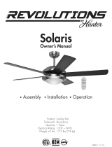
22025

Hunter Fan 22025, 21450, 21451, 21452, 21453, 22026 Owner's manual

  • Hello! I am an AI chatbot trained to assist you with the Hunter Fan 22025 Owner's manual. I’ve already reviewed the document and can help you find the information you need or explain it in simple terms. Just ask your questions, and providing more details will help me assist you more effectively!
ME018-01 r121815
Product:
Trademark:
Quantity:
Electrical Rating:
Weight ±2 lbs:
Ceiling Fan
Revolutions
1 Piece
220V ~ 50/60Hz
10 lbs (4.5 kg)
OperationAssembly Installation
Owner’s Manual
Sprite
ME018-01 12/18/2015
2
You have chosen the best. Your new Revolutions ceiling fan will provide you
with many years of comfort and satisfaction.
Congratulations!
Read and Save These Instructions
This product conforms to UL Standard 507.
WARNINGS
w.1 - To reduce the risk of personal injury, attach the fan directly to the support
structure of the building according to these instructions, and use only the hardware
supplied.
w.2 - To avoid possible electrical shock, before installing or servicing your fan,
disconnect the power by turning off the circuit breakers to the outlet box and
associated wall switch location. If you cannot lock the circuit breakers in the off
position, securely fasten a prominent warning device, such as a tag, to the service
panel.
w.3 - To reduce the risk of fire, electrical shock, or motor damage, use only Hunter
Speed Controls.
w.4 - To reduce the risk of personal injury, do not bend the blade brackets when installing
the blade brackets, balancing the blades, or cleaning the fan. Do not insert foreign
objects in between rotating fan blades.
c.1 - All wiring must be in accordance with national and local electrical codes ANSI/
NFPA 70. If you are unfamiliar with wiring, use a qualified electrician.
c.2 - Use only Hunter replacement parts.
CAUTIONS
ME018-01 12/18/2015
3
Unpack your fan and check the contents. Do not discard the box. If warranty replacement or repair is
ever necessary, the fan should be returned in its original packaging. Remove all parts and hardware. Do
not lay the motor housing on its side; the decorative casing may shift.
Tools and Materials Required
Phillips screw driver
Flat Head screw driver
Adjustable pliers or wrench
Step Ladder
Wire Cutter
Electrical tape
Unpacking the Fan
1. Disassemble the hanger ball from the downrod by removing
the set screw and lock pin at the end of the downrod. Slide the
hanger ball down the downrod and remove the support pin and
green ground screw and wire.
2. Place the green ground wire ring terminal on the ground screw
to the new downrod and tighten.
3&4. Place the hang ball on the new downrod and insert the support
pin through the holes at the top ofthe downrod. Slide the hang
ball up the downrod, putting the support pin into the slots of the
hang ball.
5. Insert the set screw through the hang ball into the downrod and
tighten.
Assembling a Longer Downrod
Washer
Support Pin
ME018-01 12/18/2015
4
Assessing the Installation Location
,8 Meters
from blade tip
to nearest wall
or obstruction
2,1 Meters
from bottom
edge of blade to
the oor
CAUTION
To reduce the risk of injury to
persons, install fan so that the blade
is at least 2,1 m above the floor.
OFF
Turn Power
1. To avoid possible electrical shock, be sure electricity is turned off at the main
power panel before wiring. AII wiring must be in accordance with national
and local electrical codes, and the ceiling fan must be grounded as a
precaution against possible electrical shock.
2. Use mounting hardware.
3. The mounting bracket should be installed to the wooden structure of the
ceiling joist with the two provided wood screws (Fig.1).
Install Mounting Bracket
CAUTION: Electrical box must be wired
to NOM general use wall switch. To reduce
the risk of injury, turn off power at wall
switch or main fuse or circuit breaker before
attempting installation or servicing.
WARNING: To avoid re or shock,
follow all wiring instructions carefully.
Any electrical work not described in these
instructions should be done or approved by
a licensed electrician.
Fig. 1
Electrical Outlet Box
Rubber Washer
Mounting Bracket
Flat Washer
Wood Screw
ME018-01 12/18/2015
5
Installing the Fan
Select Type of Installation
Standard
Standard
Low Prole
This method is preferred if the ceiling is sloped,
vaulted, or if the ceiling is extra high and
requires the use of a downrod.
This method is preferred if maximum
headroom is required. The celing must not
be at and not sloped.
WARNING: The fan must be hung with a least 2,1 m of clearance from oor to blades.
1. Slide the canopy onto the downrod (Fig. 2A). Thread the power leads from the fan through the canopy
and downrod. Take care not to pull excessively on power wires. Damage and loose connections could
result from any abnormal pressure on these wires. Set the downrod into the yoke. Rotate until the holes
match. Be careful not to damage the wiring.Insert connector pin through the holes (Fig. 2B and 2C).
Secure the pin by inserting the stop pin through the connector pin.
WARNING: Do not force the connector pin through the downrod. Use of force could cause damage to the wires inside.
Make sure the stop pin is properly engaged to prevent it from falling out. Failure to properly install locking pin as noted
could result in fan loosening and possible falling.
Fig. 2A
Fig. 2B
Fig. 2C
Ball
Downrod
Downrod
Stop Pin
Canopy
Canopy
Canopy
Power Leads
Mounting Collar Yoke
Connector
Pin
ME018-01 12/18/2015
6
2. Tighten the two down rod setscrews. Some models have locknuts for the setscrew to ensure the setscrew
is fully seated against the down rod. It is necessary to back off the locknut until it contacts the setscrew
head prior to tightening the setscrew. When the setscrew is tightened against the downrod, the locknut
should then be tightened against the connector yoke. Repeat for both (Fig. 3).
3. Tighten the motor setscrew. Check the strength of the connection (pre-tightened at the factory) by
holding the motor housing in position and turning the downrod counter clockwise. If this connection
slips, retighten the motor setscrew and locknut. Follow the same procedure mentioned above for the
downrod setscrews.
4. Install ball into hanger bracket opening. The tab opposite of the hanger bracket opening should t in
slot on ball (Fig. 4).
5. Make wire connections (refer to section titled “Electrical Connections”).
6. Slide the canopy up and fasten to the hanger bracket with the four screws provided.
WARNING: To avoid damaging the blade arms and blades, do not install either until the fan is fastened to the
ceiling. To avoid motor shift, handle fan by downrod or switch housing only.
Downrod
Set Screw
Motor Set
Screw
Ball Slot
Ball
Tab
Hanger Bracket
Fig. 3 Fig. 4
1. Fasten the canopy directly to the top of the fan motor housing with the three screws provided. (The
downrod and ball are not used for this installation) (Fig. 5A). If a metal ring washer with three holes is
provided, use it to install the canopy.
2. Hang the canopy (with the fan motor housing attached) from the tab on the hanger bracket (Fig. 5B).
This will allow you to make the electrical connections without having to hold the fan up.
3. Make the wire connections (refer to the section entitled “Electrical Connections”).
4. Put two screws in the hanger bracket, leaving them partially out (Fig. 5C).
5. Place the canopy up on the hanger bracket by inserting the slotted opening of the canopy on the
screws (Fig. 5D).
6. Insert the remaining screws through the remaining canopy holes and tighten all four screws.
Low Prole
WARNING: Failure to completely tighten the screws in step 1 could result in fan loosening and possibly falling.
Fig. 5B
Tab
Fig. 5C Fig. 5D
Slotted
Hole
Screw
Canopy
Fan Motor
Housing
Fig. 5A
ME018-01 12/18/2015
7
Warning: If there are only two wires in your existing mains wiring, this means that there is no
grounding. Under no circumstances should you wire this tting without using a grounded connection.
If you are not sure the electrical box and fan are grounded, contact a licensed electrician for advice.
The ceiling fan must be grounded for safe operation.
Wiring the Fan
Ensure electricity is switched off at the main power supply before installing or maintaining this tting. The
ceiling fan can be installed to operate in several different modes:
1. Fan controlled by pull switch, light controlled by pull switch.
2. Fan controlled by pull switch, light controlled by wall switch (not supplied).
3. Fan and light controlled by independent wall switches (not supplied).
Any switches connected to the ceiling fan must conform to the necessary local codes. If you are unsure
how to wire the ceiling fan, consult a qualied electrician. For the basic means of wiring the ceiling fan
(mode 1 above), use the following procedure:
White (Neutral) wire to the Neutral wire marked N.
Black (Live) wire to the Live wire marked L.
Green/Yellow or Green (Ground) wires from the fan and downrod to the Ground wire marked .
Ensure that all electrical conections are tight and that no loose wire strands are left out of the wire nuts.
The power supply must incorporate a 5 amp fuse and must have means of a double pole disconnection
with a separation of at least 3mm.
Installing the Blades
Fig. 5
Fig. 6
1. Attach the fan blades to the blade holder arms. Three supplied screws, washers, and nuts should be
used to securely attach each blade to each blade holder arm (Fig. 5).
2. Attach the other end of the blade holder arm to the fan motor housing using two supplied screws and
washers (pre-tted on the bottom of motor housing), for each blade holder arm (Fig. 6).
3
3
6
ME018-01 12/18/2015
8
Operating the Fan
ON
Turn Power
1. Turn power on at the the main fuse box.
2. Turn on the wall switch.
Fan Pull Chain Speed Control:
1. High
2. Medium
3. Low
4. Off
Light Pull Chain Control:
1. Light On
2. Light Off
Installing the Bulb and Glass
Fig. 7a
1. Insert a 60W max BC bulb or a 14W energy saving bulb into the lampholder. Do not use a higher
wattage lamp.
2. Secure the lamp shade (Fig. 7a) to the switch housing.
ME018-01 12/18/2015
9
Reversing the Fan
Turn the fan off and let the blades stop before changing the direction of the air flow. Engage the reverse
switch to change the blade direction.
In warm weather, ceiling fans work
best by blowing air downward
(counterclockwise) providing the
room with a cool breeze.
In cool weather, set your fan to
draw air upward (clockwise) to
distribute the warmer air trapped at
the ceiling without causing a draft.
ME018-01 12/18/2015
10
Troubleshooting
Maintenance
FAN IS NOISY
1. Use of standard light rheostat or continuously variable fan speed wall control will always cause
harmonic distortions or a huming noise. Many fan motors do not work quietly with solid state variable
controls. If a quiet wall control is desired use only 3-speed NOM approved wall controls.
2. Always allow a few days of ‘break in’ time for any new fan at medium or high speed. Try to diagnose
the exact location of the noise by listening carefully from several sides (Blades, Motor, Light Kit, etc...).
3. Make sure all screws in the fan assembly are tight and properly threaded. If not, back out and
retighten. Tighten these screws at least once a year because they may loosen slowly over time and
cause a clicking noise.
4. Make sure mounting bracket is installed snugly to junction box.
5. Make sure wire nuts in switch housing or canopy are not rattling against each other or against wall of
housing. Wrap with electrical tape if necessary.
6. Make sure the canopy is not touching the ceiling.
7. Make sure that the screws fastening blade arm to motor are tight.
FAN SHAKES OR WOBBLES
1. A small amount of movement is considered acceptable and should not be considered a defect.
2. Make sure mounting bracket is tight at junction box/ceiling with no movement at all. Tighten screws if
necessary.
3. Make sure all screws holding the blades to the blade arm and blade arm to motor are tight. Make sure
light kit/glass screws are tight.
4. Some fan movement is normal. However, interchanging an adjacent (side-by-side) blade pair may
redistribute the weight and result in smooth operation.
5. Most fan wobble problems are caused when blade levels are unequal. Check this level by selecting a
point on the ceiling above the tip of one of the blades. Measure this distance. Measurements deviation
should always be within 1/8”. Rotate the fan until the next blade is positioned for measurement. Repeat
for each blade.
FAN WILL NOT START:
1. Check all fuses or circuit breakers. Replace if missing.
2. Turn off electrical power and check all wire connections to fan and in the wall control.
FAN TURNS BUT DOES NOT MOVE MUCH AIR:
1. The fan may be running in reverse, so air is directed upward.
2. The room may contain items that obstruct the air ow.
3. The fan may be too small for size of the room.
1. The fan’s natural movements may cause some connections to loosen. A clicking or rattling noise is a
certain sign of loosening screws. Check the support connections, brackets, and blade attachments twice
a year, and tighten all screws as necessary. Make sure all screws attaching the glass to the tter on the
light kit are nger tight. Do not use a screw driver or pliers to tighten glass screws.
2. Clean your fan periodically. Use only a cloth dampened with a mild detergent solution. Never use
solvents. Dust with a soft cloth or brush. Metal nishes are nished with a lacquer to prevent tarnishing
3. You will never need to oil your fan. Its permanently sealed bearings will provide silent, trouble free
operation for many years.
4. Make sure the power is turned off at the main fuse or circuit panel before you attempt any repairs.
/