Page is loading ...

i
46R-5003A
Revised March,
1996
ZENITH
CONTROLS,
INC.
OPERATION
AND
MAINTENANCE
MANUAL
BYPASS/
ISOLATION
DELAYED
TRANSITION
TRANSFER
SWITCH
ZBTSDH
SERIES
600
THRU
1200
AMPS
MODEL NUMBER
SERIAL NUMBER
ZENITH CONTROLS,
INC
.•
830
W.
40th
St.. Chicago, IL
60609
(312)247-6400:
FAX.
(312)247-7805

STORAGE:
. . .
The
ZBTSDH
~b.o_u)d
be
stored
in
a clean dry area.
AVO_L~SJ0fit.§I:_13_!:~_EATH
STEAM OR WATER
PIPES. Excessive
mol~t~~;·m~y
d.i"m~gethe.unii::·the
switch should only be stored
~-;;-;!eve-i(h~rizontaf)
____ _
surface.
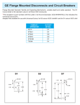
INSTALLATION:
1. Lifting:
To
lift and manuever
the
Bypass Switch use eyebolts. See Fig. 1 (below). CAUTION:
De-
pending upon
the
model, a
ZBTSDH
weighs between
1500-2500
lbs.
Use
adequate machinery
andcablestohandletheload.
·····--········-···--····-·
-
-·--
-----"-·
-·-···-··
··
·····
··
2. Equipment Preparation:
a). Check nameplate
to
assure switch system voltage and amperage
is
correct. Any discrepancy
should be immediately reported
to
a Zenith representative.
b). Lock open breakers
to
normal and emergency lines.
3.
Cabinet Preparation:
a). A small amount
of
cabinet work is required before the cables are connected. Cover the
switch and
the
controls
to
avoid metal fragments from entering mechanical and electrical
components.
b). Standard cable
entry
is through the top
or
side
of
the
cabinet.
Fig.
2 below shows one
suggested
knockout
order. For a guide
to
assist in the hole layout, refer
to
Appendix
A,
page 17.
4. Cable and Wire Connections:
a).
To
remove possible oxide, clean cable conductor with a wire brush and apply a contact
oxide inhibitor. (On aluminum cables use a stainless steel wire brush). Insert cables into
appropriate lugs.
'·b).
Connect
all
auxiliary wires for external electrical operation. Example:; E-start, remote
alarm lights
or
buzzers,
motor
control contacts, etc. Allow enough slack in wires to
allow movement
of
the
ATS (approx.
1ft.).
5.
Prior to
the
unit's energization:
a). Remove any debris incurred due
to
shipment
or
installation.
b). Inspect
the
unit, especially
the
cable and wire connections.
SPREADER
TOP
VIEW
OF
CABINET
H
NORMAL
EMERGENCY
CABINET
LIFTING
EYES
TYPICAL
LAYOUT
FIG.
2
NOte: When lifting the switch. a
spreader
must
be
used.
The
height
H mu.st
be
equal
to
D/2.
FI_G.
I
1

INSTRUCTION
NAMEPLATE
ass
-
0
-BYPASS
-
SELECTOR
SWITCH
+-MANUAL
BYPAS
s
·HANDLE
(MBHl
r--,
I 0
-+~,m----
L2
I 0 ,
1
~
L-.J
++~-----DISCONNECT
SWI}CH
(OS)
.LEA
LBE
LNA
LBN
LAI
LAT
LOS
LAH
Ll
TS
2

A.
CABINET ELECTRICAL PARTS
TAG
OE~IPnON
PART
NUMBER
LNA
LEA
LBN
LBE
LAT
LAI
LAH
LOS
Normal Available ln<licator (G)
Emergency Available Indicator
(R}
Byp<Jss
Normal Indicator (G)
Bypass Emergency ln<licalor (R)
ATS
Test Location Indicator (A)
ATS
IS<llate
Location lndicalor (G)
ATS
lnhibi: ln<licato< (R)
ATS
Disconnect
Sw~ch
..
011'.
ln<licator
(R)
Floshinq Bulb
PS-1272
CQIIIION
PARTS
BYPASS
INDICATORS
Bulb
Socket
Red Lens (R)
Green Lens
(G)
Amber Lens (A)
Y500005
PS-5046
PS-5047
PS-5048
PS-5049
L1
L2
ATS
Emer9ency Position Indicator
ATS
Normol Position Indicator
Green Lens (Normal}
Red Lens (Emergency)
Bulb Socket
Normal/
Emergency Nameplate
Emerqency Bulb
Normal Bulb
PS-5048
PS-5047
PS-5046
V-1502
PS-5105
I?S-5105
TS
Test Switch
Operator. Momentary
Contact Block N.C.
Name Plate
L-1025
L-1029
V-1503
46R-500.)
3
RFV
0-'/96

4
WIRE
ENG.
START
I
AT-I,
Z..
INTERLOCK
SOLENOIDS
VIEW
A
8TPASS/
ISOI..ATIOO
CABlNET
SWOTO<
(BP}
F'Ra-!T
INDICATOR
CONTROL
PANEL
INTERCONNECTION
DIAGRAM
DETAIL
2A
DETAIL.
26
DETAIL 2C
DETAIL
20
WITCH
AMP
& EOLES
DEPTH
"B"
..
c
..
"D"
600
600
00-1200
00-1200
3
4
3
4
19
l9
19
.19
27
3H
30-3/8
36
H
H
2
-7/8
2
7/8
23-3/4
29-1/4
-L!r'Tro
33
3/4
ARC
GIRD
ASSEMBLY
(AflC)
STATIONARY
CONTACT
ASSEMBLY
(STAT)
DETAIL I
4

B BP-BYPASS
AND
ATS AUTOMATIC
TRANSFER
SWITCH POWER PANEL
TAG
N-1,2,3,N
E·1,2,3,N
T-1,2,3,N
STAT
(SP)
STAT
(ATS)
ARC
MOV
XBN.XBE
CN/CNO
CE/CEO
AB3
AB4
AA
AT-
ACU/ACO
AI
AE
A3
A4
SN/SN2.
SNO
SE!SE2.
SEO
BPS
OS
CBE
CBN
esc
AN/A
NO
AE/AEO
No.
1
2
-4
7
--9
DESCRIPTION
Normal
Connections
CU/AL
Cable
Lugs
Emergency
Connections
CU/AL
cable
Lugs
Load
Connections
CU/AL
Cable
LUgs
Statlonuy
Contact
Assembly
Bypass
{See
Detail
1)
Stationary
Contact
Assembly
ATS
(See
Detai11)
Arc
Grid
Assambly
Kit
Movsable
Com:act
Anemblv
Mov-ble
Cont<~Ct
(Sw.
Neut.)
Bypass
Step
Down
Transformer
24
Volt
Secondary
ATS
Main
Operating
Colis
VOLTAGE
SYSTEM
Volts
Ph
Wire
Coli
Volts
120
1
2
120
120j240
1
3
240
240"
3
4
240
120/208
3
4
208
4
4 0
277/480
3
4
480
240{416
3
4
416
Bypass
Emergency
Position
Switch
Bypass
Normal
Position
Switch
Limit
Switch
DPDT.
Lever
Actuator
ATS
Auto
Location
Swltcn
ATS
Ten
Location
Swit~h
Cnnk
L_imit
Switches
ATS
Isolate
Location
Switch
Limit
Switch
DPDT.
Roller
Actuator
ATS
Emergency
Position
Switch
(Aux.
Contact)
ATS
Normal
Position
Switch
(Aux.
Contact)
ATS
Normal
Position
Coil
Cutout
Switch
DPOT
ATS
EmerSjency
Position
Coil
Cutout
Switch
OPOT
Bypass
Permissive
Pusnbutton
Momentary
"Pushbutton
Operator
N.O.
Contact
BlOCk
ATS
Solenoid
Disconnect
Switch
Operator
2-Posltlon
M11lntaln
Contact
Block
N.C.
Conact
Block
N.O.
Emergency
Interlock
Solenoid
Norm<~!
Interlock
Solenoid
Crank
Mechanh;m
Cail
CoU
Rectl1'1ers
PART
NUMBER
PART
NUMBERS
BY
AMPERAGE
400/600
100
S-2119
5-2131
(2)600MCM-2
(3)600MCM-2
S-1393F
S-1391F
(2)600MCM-2
(3)600MCM-2
S-1393F
S-1391
F
(2)600MCM-2
(3)600MCM-2
26P-ll44
26P-1126
26P-ll44
26P-ll26
2:3P-1366
23P·ll57
23P·1
157
Volbg:e•
23P-1366
26P-1125
26P·1231
R<~Ung
120/240
208/416
220/440
240/480
25VA
25VA
25VA
25VA
380
575
600
600
Pole
2
2
25VA
25VA
25VA
1200
1000
S-2132
S-2132
(4)600MCM-2
(4)600MCM·2
S-1392F
S-1392F
(4)600MCM·2
(4)600MCM·2
S·l392F
5·1392F
(4)600MCM·2
(4)600MCM·2
26P-ll26
26P-ll26
26P-1126
26P-ll26
23P·1366
23P-1366
26P·l
125
26P·1
125
26?·1231
:;:sP-1231
•P<~rt
Number
K·3061
K·3063
K-3064
K-3062
K-3067
K·3065
K-3066
PART
NUMB€
RS
BY
AMPERAGE
800
1000
1200
SPECIAL
0 R 0 E R
SPECIAL
ORDER
3
K-2146
K-2147
K-2147
K·2147
3
K·2146
i<.·2147
34
K-2147
K-2147
K-2146
K·2147
K-2147
K·21-17
3
K
2158
K2157
3.4
K
2157
K
2157
K-2158
K-2157
K-2157
K·215
7
3
I
> - t
~
L U I U
~
R
L-5021
(Oetai12B.
Poge
4)
L-3052
(0eo:ai12A)
L-3052
WITH
L-3082
(Detail
2Aond
28)
L-3054
{Detail
2C)
L-3052
l.-30S2
WITH
L-3082
SPOT
(Std.)
OPDT(OPT.)
23P-1333
23P·1334
23P·1327
23P-1328
23P-1334
26P-1304
L·1025
L·1
028
L-4009
L·l020
L-1024
K·2159
K·2159
K-2159
23P-1473

( LOCATED
ON
BYPASS
ffiAME.)
ATR
GO
·
Sf
•
41
.
811
82
.
New Solid State Time Delay
Accessories
T, U, W
Solid
State
Timers
Adjustable
in
Seconds,
Minutes
and
Hours
(Plug-ln. Style).
To select a time unit, operate the pushbuttons of the rightmost
thumbwheel switch until the desired time unit is shown in win-
dow. The time unit can be selected by pushing the plus (
+)
bot-
tom button or the minus(-) top button. The desired time
is
specified
by operating the three thumbwheel switches in the middle of the
front panel.
Setting of the timer at 000 will result
in
an infinite delay. The
min. setting for OSA-A timers is
Y,
0
of 1 second
as
shown. See
instructions.
0.1
I
0 0 1
Se~
Close
Differential
(ARSM) Relay
Adjustment
The voltage points at which the relay operates are adjustable.
When the relay pulls in, an audible click is heard, and the LED
will come on.
Setting
the
Relay:
If the relay should be set with a variable voltage supply (Variac):
l.
Turn pick-up control fully clockwise.
2.
Turn drop-out control fully counterclockwise.
3. Set Variac pick-up voltage to desired level.
4. Very
slowly
rotate pick-up adjustment counterclockwise until
relay picks up. (LED will energize).
5. Set Variac drop-out voltage to desired level.
6.
Very
slowly
rotate drop-out adjustment clockwise until relay
drops out (LED de-energizes).
Verify settings by raising voltage until relay picks up, then lower
voltage until relay drops out, making sure that relay operates at
desired voltage
levels.
(,
BYPASS S!JBPANEL
CHASSIS,.,_._-,
I
3-
1
c.
BYPASS
CCNI'ROL
PANEL,
INCLUDES
PARTS
BELOW
TAG
DESCRIPTION
PART
NUMBER
BR
Brid~e
Rectifier
'PR-Sn7h
RNH
Normal
Voltage
Relay
Y260000
R1
30
ohm
PS-4056
R2
Resistor
LDS
120
ohm
PR--4n'i.
D1,2,3,41
Diodes
:
PS-4812
(.;1
t;apacitor
RNH
PS-405tl
Ant
1
Resistor
RNH,
Aux.
Teso .ne.tay
X<'bUUV<'
-
'
G-
,

25ZII
35Zf\
•
..
0 •
•
..
CONTROL
PANEL
BASIC
CONTROLS
AUTOMATIC TRANSFER SWITCH
XN
.••.•.••
Control
Transformer,
Normal
XE
.••••.•.
Control
Transformer,
Emergency
8-
1,2,3
•.•.
Normal
Line
Phase
Relays
Undervoltag-e
Pick-up
%
Dropout
%
VFSM
••••..
Emergency
Volt-Frequency
Relay
(k-1192)
Pick-up
90%
of
Voltage-Frequency
CR.,
••.•.•
Control
Relay
(K-1204)
CCN
••••••.
CN
Coil
Control
Relay,
NOrmal (K-1120)
CCE
••.•••.
CE
Coil
control
Relay,
Emergency (K-1120)
CCNO.
.....
CNO
Coil
Control
Relay,Normal
to
Open (K-1120)
CCEO
..•.•
CEO
Coil
Control
Relay,
Emergency
to
Open (K-112(
RT
....••..
Control
Relay
Emergency (K-1204)
(E&Pass
Relay
on
Emergency
Failure)
PI
........
Delay
Engine
Start
Timer
(K-1201)
Adjustable
5
to
6
seconds
T
........
NOrmal
Restoration
Timer,
OSA-A-T
U
.•.•••..
Engine
Cool-down
Timer,
OSA-A-U
W
••••••••
Time
Delay
to
Emergency
Timer,
OSA-A"W
u(12
~
2
(13
T
*
*
u
PI
*
H
*
ON
0£1.111
ltEI..IIT
OM
IIUIIT
IIQJIT
ON
OELJI.T
REUIT
IEI<GIHE:
CVE_,...
......_.
'"""""'
"'
'""'"""
"'
"""''"""
r--
~
~
.E._
~
2!._
.E_
-
14
~
~
23
-
~
-
:zsz
~
.2:..._
~
2::.-
36
-
COI1
(FF"
QEUI.T~T
(EN:;THE
'StMTJ
81
VCl..
Tile(
SD.IS
UC
""''
l~lllOI!Ifl
XN
-~
....
C~VCI..TI'ICEI
83
82
VCI..TIII;:E
SCIISIIIC
YOt.TN;f:
SDISlNC
M:liiT
"""'
(lt()RMIIl,
II
TO
Cllll
lf<OI'!HIIL
8
TO
C•l
XE
CCNTR'a_
lltNfSFCJ!MER
CEKERCEI<T 'tOLTIICEI
VFSM
YOI..liiCE
FfiEGUEJIICT
"'-''
~lll08CII
[,~.~:
"''M
I
I"~:"'
I
.
. .
. .
.
. . . .
.
I I
.
.
I
,..
.
"'
I
R
" " "
" "
"
" "
I I
~~
~·I~·~'
,l,.lzsll'l261,·1rld·~~~~~n.~,.l,jl~··I"'H

2r
'REMOVABLE
LifTING
ANGLE.
~~~:~8-~-·---j~~~:~~---~~-.i
___
~
/
l .
•
.l
l
90
1----
1
I
I
I
I
I
I
I
I
L-
--
-b:====:f
_
_j_
~14-l--27~
.....
-
INSTRUctiON
,.....,
@
NAMO'!..ATE
L"
LN4
LON
~
LAO
c.!
B"''J>A:SS
:n:u:croR
!IWITCM
r---.
LAT
LAN
La>
L._
+-
... ANUAL
II'I':PAS:S
·
HANOL(
INSHl
r-,
JO•
'-'
,o
...
'
.,
'
L.
:.'
u
"
§
•
,.....,
.
,...
"
,..
__l
r------
A
-------llz
DIM
...
A••
CAB.
No.
ADAPT.. BAY"*
SWITCH, AMP a POLE
36"
26H-1332
3-POLE
F-1252
ZBTSDH
60
40"
F-1253
26H-1333
··
z BTSPH
80-120
3 -
POLE
40"
ZBTSOH60
-4-POLE
F-1253
26H-l333
ZBTSOHB0-120
4-POLE
F~l254
46"
26H-133~
* ADAPTOR BAY REQUIRED WHEN CUSTOMER
CONNE:CTIONS .ARE'
REAR,SIDE
OR
BOTTOM
ENTRY(SEE
36C-IOOO).OPTIONAL.
OPERATION
OF
CABINET LIGHTS
BOTTOM DOOR
l1
• • • • . . • . • • On when
the
ATS is mechanically locked in
the
Emergency
position.
L2
•••
·
.•••.••
On when
the
ATS is mechanically locked in
the
Normal
position.
TOP DOOR
LNA
•.......
On when Normal
power
is available, Off otherwise.
LEA
..•.....
On when Emergency is available,
Off
otherwise.
Note: The following will illuminate only when
the
OS
is
in
the
Inhibit position,
the
BSS is
in
the
Normal
or
Emergency position,
or
the
ATS
is
not
in
the Auto location.
LBN
.......•
On when
the
Normal Bypass (lower) contacts are closed.
LBE
.........
On when
the
Emergency Bypass (upper)
contacts
are closed.
LA T
......•.
On when
the
A TS
is
in
the
Test
location as indicated by
the
A TS location pointer.
LAI
.........
On when
the
ATS is isolated from
the
switch.
LAH
.......
.' On when
the
ATS
is
not
in
the
Automatic mode.
LOS
.........
Flashing
when
the
ATS coils are prevented from operating
by
the
OS.

DESCRIPTION
OF
MECHANICAL
AND
ELECTRICAL OPERATORS
EO
(~ass
Ooerator)
-The
bypass
operator
opens and
closes
the
bypass
contacts
BN
(~ass
11:Jrmal
Contacts).
MBH(Manual
~ass
Handle) -
Tbe
manual
bypass
handle
actuates
the
bypass
operator.
In
the
lower (open)
position,
the
bypass
contacts
BN
and
BE
are
open.
In
the
upper (bypass)
position,
the
bypass
contacts
BN
or
BE
are
closed.
BSS
(E[pass
Selector
Switch) -
The
bypass
selector
switch
determines
which
contacts
the
MBH
actuates:
turn
the
.BSS
right
for
BN
to
close,
center
to
open
BN
and
BE,
and
left
for
the
EE
to
close.
CM
(Crank Mechanism) -
The
crank
mechanism
controls
the
location
of
the
ATS:
turn
the
CM
clockwise
to
raise
and
counterclockwise
to
lower
the
transfer
switch.
Cl1
Operation
can
only
be performed
when
the
bypass
is
in
the
BN
or
BE
position.
DS
(Disconnect
Switch) -
Tbe
DS
controls
ATS
main
coil
operation.
In
the
Auto
position,
the
ATS
operates
normally.
In
the
Inhibit
position,
the
main
coils
(CN
and
CE)
cannot
be
energized,
and
the
ATS
remains connected
to
the
present
source.
TS
(Test
Switch) -
The
test
switch,
when
opened,
will
simulate
a normal
line
failure.
*For
location
of
the
preceding
operators,
see
figure
3,
page
8.
LABELS
ATS
Nllneplate -
The
ATS
nameplate
indicates
which
ATS
contacts
ar~
closed.
Nbrmal
Plate
-
The
upper
position
has
closed
Normal
contacts;
the
lower
position
has
opened Normal
contacts.
Emergency
Plate-
Tbe
upper
position
has
opened Emergency
contacts;
the
lower
position
has
closed
Emergency
contacts.
ATS
Location
Pointer
and Label -
The
red
Location
Pointer<to
the
left
of
the
Label
indicates
the
position
of
the
ATS.
Auto:
the
ATS
is
connected
to
normal, emergency and
load
buses.
Test:
The
ATS
is
disconnected
from
the
load,
but
connected
to
the
Normal and Emergency
buses.
Isolate:
the
ATS
is
disconnected
from
the
Normal, Emergency and
load
buses.

ZBTSDH PURPOSE
ZBTSOH: Bypass/Isolation Switch (BP) and Automatic Transfer Switch
(ATS)
combination provides means
to maintain continuity of source lines to critical loads
in
either of two modes:
I.
Automatic:
Auto Operation Mode allows the
ATS
to determine the load's power source.
il. Manual: Manual Operation Mode allows the operator
to
manually connect the load
to
either available
power source. This mode is allowed only
in
the "Isolate" and
"Test"
positions.
OPERATION
The Auto Operation Mode occurs when "AUTO" is indicated by the
ATS
Location Pointer, the
OS
is "AUTO"
the BSS is
"OFF"
and
BP
is
"OPEN."
Auto to Test -
To
change the
ATS
location from Auto to
Test,
turn the
OS
to the"INHIBIT'position. Switch
the BSS to the same source that powers the
ATS.
Note:
The
BP will not allow cross phasing; any such opera-
tion is prevented by safety interlocks.
Move
the MBH up. The
ATS
is bypassed.
Rotate the CM counterclockwise until the
ATS
Location Pointer is aligned with
"TEST'
(Note: The
BP
can
act as a manual transfer switch only when the
ATS
is located in
"TEST"
or "ISOLATE.")
The
"TEST"
loca-
tion permits the user to verify the
ATS
operation.
To
sequence the
ATS,
review the drawing supplied with
the unit and refer
to
the "TEST PROCEDURE," page 12, and "TROUBLESHOOTING GUIDE," page
14.
....
4-J
Test
or
Isolate
-To
change the
ATS
location from
Test
to Isolate, turn the DS to INHIBIT. Rotate
CM
counter .clockwise until the
ATS
Location Pointer is aligned with "Isolate:•
ATS
Removal - DO NOT REMOVE THE
ATS
UNTIL
THE
HARNESS MULTIPIN PLUGS
HAVE
BEEN
DISCONNECTED (connections to
A3
and
A4
and any other· customer options should be disconnected).
To
remove the
ATS,
rotate the four
panel
latches to the vertical position (Fig.
3,
page 8). Pull the
ATS
outward
until the slide brackets are fully extended. Engage slide locks to prevent movement of the brackets. (See
Fig.
5). Connect a lift bar (similar to Fig. 4) to the
ATS
lifting brackets. ·
0
LIFTING
BRACKETS ON
ATS
FIG. 4
10

ZBTSDH
OPERATION
OF
AUTOMATIC
TRANSFER SWITCH
OPERATION:
When
the
normal
line
(NL)
falls
to
the
preset
dropout
point,
or
if
any
normal
phase
fails,
the
phase
relay(s)
will
drop
out
disconnecting
the
CR
relay.
Pl
drops
out
after
.5
to
6
seconds
(adjustable)
and
signals
generator
to
start.
When
emergency
line
(EL)
voltage
and
frequency
reach
at
least
90%
of
rated
value,
the
VFSM
relay
is
energized.
The
RT
relay
is
now
energized
to
operate
the
CNO
relay
thru
the
SE
cutout
switch
causing
the
main
transfer
coil
CN/0
to
operate
thru
the
SCNO
limit
switch.
The
load
is
now
transferred
to
the
open
position.
The
SNO
and
SCNO
limit
switches
.operate
to
disconnect
the
CNO
relay
and
CN/0
transfer
coil.
The
transfer
switch
is
now
locked
mechanically
open.
SNO
now
is
deactivated.
This
energizes
the
DW
timer.
After
time
setting
has
lapsed,
DW
will
energize
CEl,
which
will
energize
main
transfer
coil
through
the
SCE
and
CEL
The
load
is
now
transferred
to
the
emergency
line
supply.
The
SE
and
seE
limit
switches
operate
to
disconnect
the
CEl
relay
and
CE/0
main
transfer
coil.
The
transfer
switch
is
now
locked
mechanically
in
Emergency
position.
When
the
normal
line
voltage
restores
to
the
preset
value,
the
phase
relay(s),
(Bl,2,3)
operate
to
energize
the
normal
restoration
timer
T.
After
the
time
setting
has
lapsed,
the
timer
contact
closes
to
energize
CR
relay.
The
CEO
relay
is
now
energized
thru
the
SN
and
SEO
limit
switches,
causing
the
main
transfer
coil
CEO
to
operate
thru
the
SCEO
limit
switch.
The
load
is
now
transferred
back
to
Open
position.
The
SEO
and
SCEO
limit
switches
operate
to
disconnect
the
CEO
relay
and
CE/0
transfer
coil.
The
transfer
is
now
locked
mechanically
open.
SEO
is
now
activated,
energizing
DT
timer.
After
time
setting
has
lapsed,
DT
will
energize
CNl
which
will
energize
main
transfer
coil
through
the
CNl
and
SCN.
The
load
is
now
transferred
to
the
Normal
line
supply.
The
SN
and
seN
limit
switches
operate
to
disconnect
the
CNl
relay
and
CN/0
main
transfer
coil.
The
transfer
switch
is
now
locked
into
Normal
position.

OPERATION (continued)
Test Procedure- The ATS can
be
tested
in
either
of
two
locations:
1
).
"Auto
Location": To run a test
in
the
auto
location,
two
methods are possible. (The Normal
source must be available for each):
a). Control Panel
Test-
A control panel
test
checks
the
operation
of
the ATS without breaking
the
load connections. To use this procedure,
tum
the
DS
fo
"INHIBIT"(See
Fig.
3,
page
81
Turn
the
TS to
"TEST."
Hold
the
TS until
the
CCNO picks up (see page 6; ATS control panel).
(Note:
if
the
CCNO
does
not
energize
after
theW
time delay, release the
TS
and refer to Table
3 Page 14). Release
the
Test Switch; the spring-loaded TS will move back
to
"AUTO". The
CR
picks up after the T time delay has elapsed. (If
the
CR does
not
energize, refer
to
Table 3). The
control panel test method
is
complete.
b). Full Transfer
Test-
A full transfer
test
checks the complete operation of the ATS by trans-
ferring the load's power source from
"Normal"
to
"Emergency."
To
use
this method, turn
the
DS
"ON." (See
Fig.
3,
p. 8). Hold the TS until the ATS transfers to Emergency. (Note:
If
the ATS does
not
transfer aher
theW
time delay, release the TS and refer to Appendix
B).
Release the Test Switch;the spring-loaded TS will move back
to
"Auto."
The
ATS
will
transfer
back
to
Normal aher the T time delay has elapsed. (If
the
ATS does notre-transfer, refer to
Table 3). The full transfer
test
is
complete.
2).
"Test
Location": The
"TEST"
procedure
is
used after maintenance or repair
of
the ATS. To
use this method, the
BN
contacts should be closed and
the
Normal source must
be
available.
In
the
"TEST"
location, the ATS
is
disconnected from the load bus. The same two options,
as
descrlbed
in
the "AUTO" location, are present. Refer
to
1-a, b for the procedure.
CAUTION: A "Control Panel Test,"
or
a test with
the
ATS in the "TEST" location runs the
emergency source with no load. A
no
load operation may be detnmental to
the
engine, and the
engine generator manufacturer should be consulted.
Allow sufficient time on the U timer for the engine
to
safely cool down.
RECOMMENDATIONS: The suggested range on the T
timer
is
0-30 minutes. A test
is
recom-
mended at least once a month. Hospitals test
the
ATS once a week.
NOTES
ON
OPERATION
CAUTION: When the ATS
is
located
in
"TEST"
or
"ISOLATE."
the
BP
acts
as
a Manual Transfer Switch.
The user should be aware
that
the
manual bypass has
two
cautionary states:
1
).
The
BP
cannot be transferred without
at
least
one
source (Normal
or
Emergency) available.
2). The transfer from
BE
to
BN
results
in
a momentary loss
of
power
to
the load while
BP
is
open.
In
the
event
of
a failure and
the
ZBTSDH
is
not
in
the
Auto
Operation Mode, a manual transfer
of
the
BP
is
required. When the
BN
contacts are closed, the energency generator starts after a six second delay.
(Note. Transfer only after the generator
is
verified to operate properly). To manually transfer the
BP,
depress the
BPB,
pull the
MBH
down and then, switch
the
BSS
from Normal to Emergency. The
BSS
movement through the open position, Normal
to
Emergency, temporarily opens the engine start contacts.
Once
the
BSS
is
in
Emergency, the engine start contacts remain closed.
Move
the
MBH
upward
to
com-
plete
the
manual transfer
to
the
BP
to
the Emergency position. The Emergency generator presently powers
the load through the
BP,
BE
contacts.
To
obtain the
BN
position (Note: Verify Normal Source is Available) when the
BE
contacts .are closed,
Move
the
MBH
down. Switch
the
BSS
from EMERGENCY to NORMAL.
Move
the
MBH
up; the
BN
contacts are closed, and the normal source powers the. load. (For a summary
of
the
ZBTSDH
operations and
permitted BP/ATS movements, see Table 1,2).
12

TABLE
1 ZBTSDH STATES
X
DEOOTES PERMISSIVE
COMBINATION
ATS
BYPASS
SWITCH
MODES
LOCATION
ATS
POSITICtl
EM
ERG.
OPEN
NORMAL
NOT
NOT
IN TRAVEL
NORMAL
ALLOWED ALLOWED
X
(NON-All
GN
ED
NOT
NOT
EMERG.
POINTER l
X
ALLOWBl
ALLOWED
AUTO
NCR
MAL
A'
~~l.o-n
X X
POINTER
NOT
EM
ERG.
ALIGNED
ALLOWED
TEST
X
X
)<
NOOMAL
X
X*
POINTER
ALIGNED
EM
ERG.
'i
X
'~*
ISOLATE
)< )<
NORMAL
x
POINTER
*
EMERG.
)<
ALIGNED
X
)<
*
TABLE
2 ZBTSDH 2 WIRE
ENGINE
CONTROL
CONTACT
BSS
SELECTOR
SWITCH
POS.
LOCATION
ATS
EMERG.
OFF
NORMAL
IN
TRAVEL
NOT
*
CLOSED
(NON-
ALIGNED
OP.EN
ALLOWED
POINTER}
AUTO
ATS
OPEN*
ClDSED
POINTER
Cet<TROL
POSITION
TEST
ATS-l<-
ATS
CLOSED
POINTER
CONTROL
ISOLATE
CONTROL
POSITION
ATS
POINTER ClDSED OPEN
*
CONTOOL
POSITION
*IF
NORMAL
IS BYPASSED
AND
NORMAL
SOURCE
FAILS
THEN
AFTER
6 SECOND
DELAY
RNH
RELAY
WILL
DE-ENERGIZE
CLOSING
ENGINE
START
CIRCUIT.
13

I
AtsLt:.
.J
I
nuUOLt:
~HUU
J
lNG"
DECISIONS
PROCESS
CORRECTIONS
,.
iUN•-1.!! s
1
...
uc. ..
10
iUf
I
IUHflt,
Tfl...,..!!'
(JII
1'0
(M(JIIG(,.cYI
'T.CR.U.PI.H
DE-ENERGIZES
£-STAAT
C.Q.S(S
TO
srA~T
(HCIH(
._
HOT£!
D(LAT
W H
OR
P
USED
t.
ATS
TOII.t.NSF(itS
TO
OIC:JtG£NCT
ANO
..
(CKANIC.l.U..Y
LOO::S.
2.. t,IWCT
!I'W1TC~£S
:Sf;. A:!
ARE
.lCTIVATEO
3.
U
IS
EN:ERGilEO
T
~~GINS
TlloiiHG
CR
E!-l!i'IGIZ:!:O
1.
ATS
Tlt;.."SJ'"(RS
TO HORUAt.. .
-0
Joi£CK.2.HIC
...
Lt..T t..OCXS.
Z..
L""IT
SWI001(S
SH
......
"'"'(
...
CTUATCC.
].
L2
IS
ENE.~Gil£0.
<4.
U
BEGINS
TlloCINC.
O<ECX
I#
L't<Om(
:ST.lJIT
OIICUIT
J:S
.II(C(NIHG
C:·OlHT.lCT
O..C:SUJI(.
CHANGE W
TO
FINITE
SETTING
>'!E<'!.._---------1
!:
:~~:~~~~;;;If
c..
.
CQ<oOf't,.II;Tl T
....
u•<:.
1.
TVOII.
..
CIS
1'0_0
..
.
I.
OI(CX:
Sl.
Z.
l
'IOI..T~(
S(;i"~G.
Z.
OIEC:ot C.!:I'"EC7Wt:
rf!,\SE
it!L'-t.
1
~t~os:r.·urc
...
l.
CH(C.C.
'SOt..(NOIO.
l
flti"I!_.T
T'!~T
CHANGE U
TO
FINITE
SE'ITINC
I. Oti!:C:ot
0(1£CTIV("
(N<:IIC(
STAAT
O(V1C(..
1.
(NGIN(
:sl-1UT•CO
....
H.
2..
TCST
COW
..
l.(TE.
14

MAINTENANCE
ELECTRICAL TEST
The
ATS
may
be electrically tested (refer
to
operation:
"Test
Procedure"). After completion
of
an electrical
test,
the
ATS may be returned
to
the
Auto
Operation Mode (follow
the
instructions
in
the
Operation
section).
If
the
ATS malfunctions,
troubleshoot
the
switch and replace any
faulty
part(s) immediately.
(A
PROBLEM/REMEDY CHART
is
located
in
Table
3,
page 14).
INSPECTION
Contacts
.
The
movable and
stationary
contacts
are a vital
part
of
the
ZBTSDH and
must
be
kept
clean.
To
inspect
the
ATS contacts remove switch (see Operation section). Examine
the
contacts.
Any
surface deposits
must
be removed with a clean cloth
(DO
NOT USE EMERY CLOTH
OR
A FILE).
A
thin
black film can be wiped clean
with
a cloth dipped
in
solvent. After
the
movable contacts
and
stationary
contacts are clean (no discoloration
or
deposits) return
the
ATS
to
the
Auto Operation
Mode.
Multilams.
To
inspect the multilams, remove
the
ATS (see Operation instructions). The multilams are the
vaned
connectors
and lower buses (see Fig.
6).
Examine the multi lams. Verify
that
all
the
vanes are present,
unbent
and uncorroded. Any defective parts should be replaced before
the
ATS resumes normal operation.
/•
:"-.
,
I
r=-=--,,
1
IL',;::c::c.
'li
~~~~~~~~~~~~(
.J't_
__
;~
tr
----n
,.
11
1:
II
•,
II
II
IJ
,.
'•
.:
"
::
::
VANES
WLTILAM
[
FIG. 6
Current
Carrying
Parts.
An
easily detected
but
abnormal condition
is
the
discoloration
of
current carrying
parts (particularly copper). Discoloration appears
as
darkened materials
or
finishes. Any discolored parts
should be cleaned. WARNING: ANY MAINTENANCE SHOULD ONLY
BE
DONE
WHJ
LETHE
POWER
IS
OFF!
If
the
discoloration persists,
contact
the factory.
LUBRICATION
The cams
of
the
ZBTSDH are lubricated with
"Dow
Chemical's
Molykote"
(321 R
or
GN
paste), and
the
gears
are lubricated with Lubriplate 105. These lubricants provide adequate lubrication for a clean and properly
maintained switch's lifetime. Should debris
contaminate
the
mechanism, clean and apply additional lubri·
cants (321
R,
GN
paste
or
Lubriplate).
LUBRICATION MAINTENANCE CHART
DATE
DATE
INSPECTED
LUBRICATED
LUBRICANT
USED (CAMSI (GEA.RSI
NOTES
15

TORQUE REQUIREMENTS FOR
FIELD
CONNECTIONS
NOTICE.
TIGHTENING TORQUES
FOR
FIELDWIRING
TERMINALS
...
·
Socket Size
Across Flats, Inch
1/8
5/32
3/16
7/32
1/4
5/16
3/8
1/2
9/16
Tightening Torque
Pound-Inches
45
100
120
150
200
275
375
500
600
TORQUE REQUIREMENTS FOR
ELECTRICAL
CONNECTIONS
All
current carrying parts
use
compression washers and should
be
torqued to the values presented below.
Caution: DO NOT OVE RTORQUE WASHERS;
follow
the given torque values.
TORQUE REOUI REMENTS
(inch-
lb. except denoted
by+
are
ft
-
lb)
BOLT
SIZE
GRADE 5
SOCKET
HEAD
SET
SCREW
COMPRESSION
WASHERS
1
2
1/4-
20
75 120 52 80 87
5/16-
18
157
225 105 159 170
3/8-
16
+23
412
165 +23 +26
1/2
- 13 +57
1030
386 +56
+59
WIRE CONNECTION
LUG BOLTING TORQUE
TIGHTENING
TORQUE
BOLT
D
lA
(inch)
TORQUE
(ft
-lb)
WIRE
COND. SCREW
DRIVER
SIZE AWG
or
MM TORQUE (inch - lb.)
1/4
OR
LESS
6
5/16
11
3/8
19
7/16
30
1/2
40
5/8
OR MORE
55
18-16AWG
19
14.
8
19
6-
4
36
!&;

APPENDIX
A
LNISTRUT
PANEL
TH
AOX.
•ADAPTER
FRON
BAY\
TOP
VIEW
-
-iG
f--
F
-
~-t:
~
~
-b
L;
;::;~
~'"::::
~+
T
r:j
I
N
-.
~~
CHANNEL
I
4~6
t
REF.:
A
, T
8
v
_i_.
N
I !_
c
'MD
N
__._
t
• 0
w
C-"'
NET
APf>
~I
I
_i
88
~m
NOR~AL
L:Ujs
E
J
l--H-=J
~
_jd--K-
I
f--M
nTr
u
FRONT
-
l
<?)
®
~
·c;::;-
~
l=§CD
I
Q)E
r4la
~
1J
~
NORMAL
LUGS
I
®
G)-lOAD
LUGS
@-EMERGENCY
LUGS
I
NO
CONDUIT
ENTRY
'
SIDE
VIEW
t-14':.]
l J
j I
R
I
l
87~
•
CABINET
HEIGHT
90"
NOTE: Dimensions are
subject
to
change.
If
critical
dimensioning is requirl!d.
contact
factory.
•AOAPTOA
BAY
REQUIRED
WHEN CUSTOMERS
CONNECTIONS
ARE
REAR,
SIDE
OR
BOTTOM
-ENTRY' IOPTIONALI.
UNIT
A B
c D E
F
G
H J
K
L M
N
p
a
R
s
T
u
v I
w
:STSOH
60
3P
14
5/8
4
1/4
4
1/4
1
13/16
12 1/2 3
118
3 318
2
112 8
1/8
2 118
18
1/8
33
114
22
5/8
,
J9
1/2
35
3/4
:BTSOH
60
4P
'3
3!4
18
314
4 114 4
1/4
1
5/16
121/2
"18
5
5/8
2
1/2
3
3/8
2
1/2
2 118
18
118
26
3/4
33
114
22
5/8
,
39
1/2
25/81393/4
:STSOH
80-120
!P
15
5 5
1
1/8
12
JIB
3
114
- -
4
1/4
3 7 318
21f2
18
118
-
JJ
7/8
22
518
29
3/8
38
3/8
39
J/4
~BTSOH
80-120
4P
10
SIS
20
SIS
5 5
1 1/'2
1'2
3/8
3
1/4
5
tiS
'2
11'2
4 1{4
3
-
'2
1{'2
18
118
'24
7/8
337/8
'2'2
5/8
'29
J/8
38
3/8
'21/'21453/4
NOTE:
ALL
DIMENSIONS
ARE
FROM
THE
INSIDE OF
CABINET.
17

APPt:I\IUIA
D
LO
1
vun
vr
C.nl-\
1
lVI
\I
OPERATIONAL
FLOW
BYPASS POSillON
BYPASSED
ATS
MBH
POSITKlN
[lj(EMER)
LOCATION
POINTER
M4
NL~~
:~
l-"M"'3'----IN~~S
T
:rs
....
~---
,..
AUTO
BE
,..
~~a~
I
I
cz
1
I
I
I
I
C41
I
I
M
M6
MB
Ml
M9
I
1
c1
I
I
NL*~
BN
T
ATS
BE
EL!
! .
~
M9
TEST
,..
,..
,..
~~-:I:=S:::cOL:-A::::T::::E:--
DIRECTIONAL PATH KEY
M# Manual Bypass Handle (MBH)
Operation
(See
Note
3,
4)
C#
Manual Crank Mechanism
{CM)
Operation
-----
..... (See
Note
4)
~
Manual Bypass Selector Switch (BSS) Opera-
tion
NOTES
1.
When
operating
CM
between
-
"Auto'~
and
'"Testn
location,
BP
and
ATS
switch
must
parallel same
source.
2.
One source - Normal
or
Emergency -
must
be
available
to
operate
ZBTSDH.
3.
'Always
depress BPS
prior
to
and while
operating
MBH.
4.
Always
verify
"OS"
switch
is
in,.INHIBIT"
po~ition,
prior
to
operation
of
MBH,
CM
or
BSS.
5.
When
ATS
is in
the
"Test"
or
"Isolate
..
locations,
opening
a Bypass
switch
will
disconnect
the
load from
the
Power
Source.
CHART OVERVIEW
The
left
index
of
chart
re'presents
location
of
ATS
controlled
by
the
operation
of
CM.
The
top
index
of
chart
represents
position
of
MBH handle
and
within
the
chart
are
positional representatiQn
of
BSS.
The
arrowed
paths
M#, C#.
B#
give directional flow
of
operation
of
MBH,
CM
and
BSS respectively.
EXAMPLES
t
ATS
Auto-operation:
A.
To
Bypass Normal and Isolate
ATS.
1. Follow path B1, M1.
C1
and C3.
2.
To
return
to
the
original position follow
path;
C3, C1.
M3
and BA.
B.
To
Bypass
Emergency
and Isolate
ATS:
1. Follow path B2. M2, C2 and C4.
2.
To
return
to
original
position
follow
path;
C4,
C2,
M4 and BA.
II. Normal Bypass/Isolate
to
Emergency
Bypass/Isolation:
1.
If
Normal
Source
fails follow
path;
M11,
Bl,
B6and
M10.
2.
To
return
to
original position follow
path;
M12,
Bl,
B5 and M9.

FIELD
NOTES
MODEL
NO:--------------------------------------------------------
SERIAL
NO:----------------------------------------------------------
DATE
SHIPPED:--------------------------------------------------------
START-UPDATE:-------------------------------------------------------
DRAWING
SUPPLIED:----------------------------------------------------
TEST
AND
MAINTENANCE
NOTES:
OBSERVATIONS
NOTES
TESTED
DATE
19
/