16
1. Wiring diagram of indoor unit
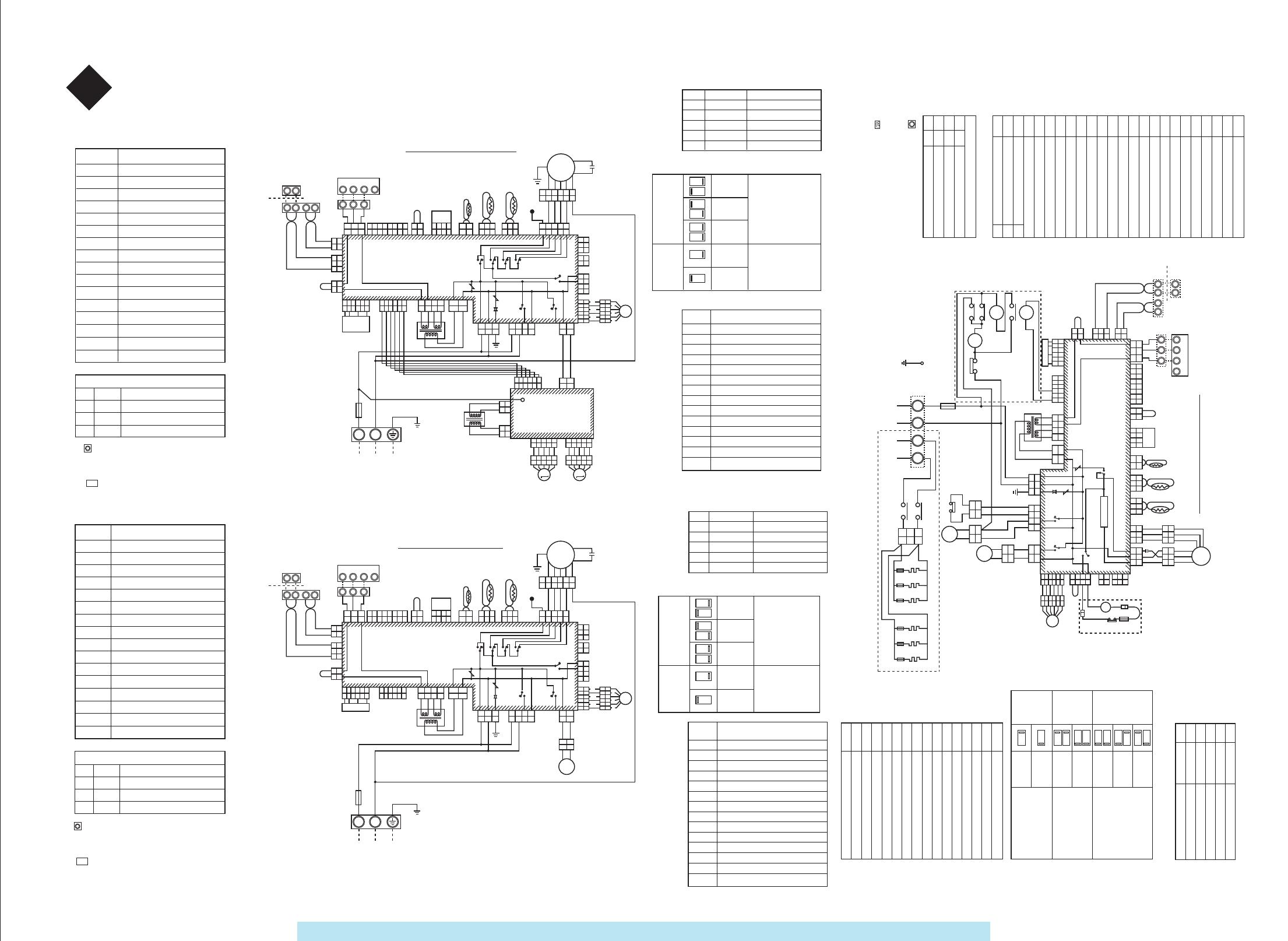
4 Wiring diagram
Circuit diagram of built-in type unit withairflow in four directions
Special indoor unit for MRV intelligentnetwork air conditioner r
outdoor
unit
Centralized
control
terminal
Indoor
and
outdoor
commu-
nication
terminal
brown brown
gray gray
control base plate
orange yellow
blue
pressure
sensor
blue
white
black
white
white
red
orange
blue
red
black white
white
white
red
white
red
white black
red
white
white
black black
white
white
black
white
earthing screw
for indoor unit
power supply
of indoor unit
only for electric heating model
power supply ofelectrical heaterl
only for electric
heating model
Symbol
Name
LED indicates
Orange
Serial signal input of linear controller
Green
Serial signal output of linear controller
Red Indoor abnormality
Yellow
LAN signal output of outdoor unit
FM
RC
TR1,2
TA
TC1A
TC2
RY01,02,03,04
RY05
RY06
RY07
HA
GM1,2
F1
PMV
TNR
DSA
LED
D08
D10
D16
D17
Motor for airflow (built-in thermal protector)
Running capacitor
Supply transformer
Ambient temperature sensor
Indoor heat exchange sensor
Indoor heat exchange sensor
Fan control relay
Fan control relay
Control relay for drainage pump
Control relay for air deflector
JEMA standard HA terminal-A
Motor for air deflector
Fuse 5A 250VAC
Electronic expanding valve
Piezoresistance
Discharge tube
1. indicates terminal block; internal words
express code of terminal block.
2. Dotted line indicates wiring on the spot.
3. indicates PCB
4.For the method of connecting with outdoor unit, please refer to the wiring diagram attached to each model.
1. indicates terminal block; internal words
express code of terminal block.
2. Dotted line indicates wiring on the spot.
3. indicates PCB
4.For the method of connecting with outdoor unit, please refer to the wiring diagram attached to each model.
Symbol Name
Motor for airflow (built-in thermal protector)
Running capacitor
Supply transformer
Ambient temperature sensor
Indoor heat exchange sensor
Indoor heat exchange sensor
Fan control relay
Control relay for electrical heater
Control relay for drainage pump
Control relay for air deflector
JEMA standard HA terminal-A
Motor for air deflector
Fuse 5A 250VAC
Electronic expanding valve
Piezoresistor
Discharge tube
LED indicates
Orange
Serial signal input of linear controller
Green
Serial signal output of linear controller
Red
Indoor abnormality
Yellow
LAN signal output of outdoor unit
FM
RC
TR
TA
TC1A
TC2
RY05
RY01,02,03,04
RY06
RY07
HA
GM
F1
PMV
TNR
DSA
LED
D08
D10
D16
D17
Switch function
Rotary switch
For setting unit code of indoor unit
Dial switch (7P)
For setting centralized control address
Dial switch (3P)
For TA temperature modification when heating
Dial switch (1P)
For emergency running
Dial switch (4P)
For setting HP of indoor unit
Dial switch (2P)
For testing rated capacity
Setting state
when
delivering
Setting of TA
temperature when
heating;
Modification
4deg
6deg
Setting state whendelivering
When it is in ON state,
the max. power will be
transferred into rated
power after 29 minutes
Inspection code
Inspection part (Inspection
Ambient temperature sensor (TA) circuit
Indoor base plate circuit
Indoor heat exchange sensor (TC1A) circuit
Indoor heat exchange sensor (TC2) circuit
Centralized control communication circuit
Centralized control address setting
Linear controller mismatch wiring
Mismatch wiring of indoor unit
Judgement for insufficient circulation of refrigerant
Expression of external output
Expression of external interlocking
Circuit of indoor pressure sensor
Expression of insufficient refrigerant
ON
1 21 21 21 21 2
ONONONONONON
SW01
SW02
SW03
SW04
SW05
SW07
OFF
ON
11
OB
OC
11
12
93
94
97
98
99
9A
9F
B5
B6
B9
Ed
Setting content of dial switch
(TA setting)
SW03
SW06
SW07
Switch function
Rotary switch
For setting unit code of indoor unit
Dial switch (7P)
For setting centralized control address
Dial switch (3P)
For TA temperature modification when heating
Dial switch (1P)
For emergency running
Dial switch (4P)
For setting HP of indoor unit
Dial switch (2P)
For testing rated capacity
Setting content of dial switch
(TA setting)
Setting state
when
delivering
Setting of TA
temperature
when heating;
Modification
4deg
6deg
When it is in ON state,the max. power will
be transferred into
rated power after 29
minutes
Inspection
code
Inspection part (Inspection place:
indoor unit)
Ambient temperature sensor (TA) circuit
Ambient temperature sensor (TA) circuit
Indoor base plate circuit
Indoor heat exchange sensor (TC1A) circuit
Indoor heat exchange sensor (TC2) circuit
Centralized control communication circuit
Centralized control address setting
Linear controller mismatch wiring
Mismatch wiring of indoor unit
Judgement for insufficient circulation of refrigerant
Expression of external output
Expression of external interlocking
Circuit of indoor pressure sensor
Expression of insufficient refrigerant
Switch function
Rotary switch
For setting unit code of indoor unit
Dial switch (7P)
For setting centralized control address
Dial switch (3P)
For TA temperature modification when heating
Dial switch (1P)
For emergency running
Dial switch (4P)
For setting HP of indoor unit
Dial switch (2P)
For testing rated capacity
Setting content of dial switch
(TA setting)
Settingstate whendelivering
Setting of TA
temperature
when heating;
Modification
4deg
6deg
When it is in ON state,the max. power will betransferred into ratedpower after 29 minutes
Inspection
code
Inspection part (Inspection place:indoor unit)
Ambient temperature sensor (TA) circuit
Ambient temperature sensor (TA) circuit
Indoor base plate circuit
Indoor heat exchange sensor (TC1A) circuit
Indoor heat exchange sensor (TC2) circuit
Centralized control communication circuit
Centralized control address setting
Linear controller mismatch wiring
Mismatch wiring of indoor unit
Judgement for insufficient circulation of refrigerant
Expression of external output
Expression of external interlocking
Circuit of indoor pressure sensor
Expression of insufficient refrigerant
Symbol
Name
Motor for airflow (built-in thermal protector)
Running capacitor
Supply transformer
Ambient temperature sensor
Indoor heat exchange sensor
Control relay for electrical heater
Control relay for drainage pump
Control relay for air deflector
JEMA standard HA terminal-A
Motor for air deflector
Fuse 5A 250VAC
Piezoresistance
Electronic expanding valve
1. Indicating terminal block; internal
words express code of terminal block.
2.Dotted line indicates wiring on the
spot.
3. indicating PCB4.For the method of connecting with outdoor unit, please refer to the wiring diagram
attached to each model.5.Circuit diagram of built-in type unit with airflow in four directions
Yellow
LED indicates
Orange
Serial signal input of linear controller
Green
Serial signal output of linear controller
Red
Indoor abnormality
LAN signal output of outdoor unit
LED
D08
D10
D16
D17
W
Convertible type circuit diagram
Special indoor unit for mrv intelligent
network air conditioner
outdoor unit
Central
controller
terminal
Indoor & outdoor
communication
terminal
BR
GR
low voltage
Remote controller
OR Y
B
pressure
sensor
B
W
W
BL
W
W
R
Indoor unit power
MCC-1336
OR
BL
R B W
W
W
R
W
R W B R W
BL
W
B B
WW
R
R
Y/G
WW
OR
W
Wiring diagram
Special indoor unit for MRV
intelligent network air conditioner
outdoor unit
Centralized
control
terminal
Indoor & outdoor
communication
terminal
low voltage
MCC-1334
Remot controller
OR Y
BL
B
W
BL
W
W
R
OR
BL
R B W
W
W
R
W
W
B B
Y/G
W
W
BL
BR
GR
W
W
B
W
W
OR
BL
R B W
BL Y OR R OR BL Y OR R
BR
GR
BR
GR
W
W
B
W
W
pressure
sensor
OR
BL
R B W
W
W
OR
BR
R
BL
Y
6
4
3
6
4
3
1 1
2
5 5
2
PMV
W
OR
BR
R
BL
Y
6
4
3
6
4
3
1 1
2
5 5
2
PMV
R W B
Indoor unit power supply
CN23
white
CN24 black
CN15 white
CN02
white
CN6 white
MCC-1256-08
P
Q
P
X
Y
Q
A B C D
A B C
1 2 3
1 2 3 1 2 3 4 5 6 7 8
1 2 3 4 5 6 7 8 1 2 3 4
1 2 3 4
2
2
1
1
2
2
1
1 23 1
23 1
23 1
23 1
1
2
3
1
2
3
1
2
1
2
1
3
5
1
3
5
7 7
5
1
2
3
1
2
3
4 4
5
6 6
6
4
3
6
4
3
1 1
2
5 5
2
1
1
3
3
7 1
7 1
3
3
5
5
1
1
3
3
5
5
1 4
1 4
3
3
2
2
1
1
3
3
1
1
3
3
5
5
2
2
4
4
6
6
1
1
3
3
5
5
2
2
4
4
6
6
1
2
1
2
1
2
1
2
3 3
1
2
1
2
F1
TR
CN03
CN10
CN8
CN01
CN13
CN12
CN14
AC12.5V
CN26
HA
JEM-A
CN04 CN05 CN21
TC2
TA
TC1A
FM
CN07
CN19
CN17
CN08
CN25
CN09
RY07
RY05
RY06
TNR
DSA
RY01
TNR
1
1
3
3
5
5
1
1
2
2
3
3
1
1
2
2
3
3
4
4
5
5
6
6
RC
52H
TF
26T
PMV
1
1
3
3
1
1
3
3
1
1
3
3
GM
DM
L N
HL HN
Hu
23Hu
250 5A
50Hz 220v
50Hz 220v
GS
52H
H
F2
H
F2
H
F2
H
F2
H
F2
H
F2
FM
RC
TR
TA
RY01
RY05
RY06
RY07
HA
GM
KM
CS
F1
PWV
TNR
H
52H
26T
TF
F2
Hu
23Hu
SW01
SW02
SW03
SW04
SW05
SW07
ON
1 21 21 2
ONONONON
SW03
SW07
OFF
ON
1 1
OC
12
93
94
97
98
99
9A
9F
b5
b6
b9
Ed
Ed
SW01
SW02
SW03
SW04
SW05
SW07
ON
1 21 21 2
ONONONON
SW03
SW07
OFF
ON
1 1
OC
12
93
94
97
98
99
9A
9F
b5
b6
b9
Ed
Ed
P
Q
P
X
Y
Q
A B C D
A B C
1 2 3
1 2 3 1 2 3 4 5 6 7 8
1 2 3 4 5 6 7 8 1 2 3 4
1 2 3 4
2
2
1
1
2
2
1
1 23 1
23 1
23 1
23 1
56 2
56 2
3
3
4
4
1
1
1
2
3
1
2
3
1
2
1
2
1
3
5
1
3
5
7 7
5
1
2
3
1
2
3
4 4
5
6 6
79 1
79 1
3
3
5
5
1
1
3
3
7 1
7 1
3
3
5
5
1
1
3
3
5
5
1 4
1 4
3
3
2
2
1
1
3
3
1
1
3
3
5
5
2
2
4
4
6
6
1
1
3
3
5
5
2
2
4
4
6
6
1
2
1
2
1
2
1
2
3 3
1
2
1
2
12
12
13
1
L N
13
13
1
1
2 3 4 5
2 3 4 5
1
1
2 3 4 5
2 3 4 5
1
1
2 3 4 5
2 3 4 5
1
1
2 3 4 5
2 3 4 5
CM2 CM1
CN5
CN6
CN4
CN3 CN2
L
TR2
1PH,220-230~,50Hz
F1
TR1
CN03
CN10
CN16
CN01
CN13
CN23
W
CN12
CN24
CN15
CN02
CN14
AC12.5V
CN6 W
CN26
HA
JEM-A
CN04 CN05 CN21
TC2
TA
TC1A
FM
RC
CN07
BL
CN19
CN17
CN08 R
CN25
CN09
RY07
RY05
RY06
TNR
DSA
RY
01
RY
02
RY
03
RY
04
MCC-1334
TNR
P
Q
P
X
Y
Q
A
B C D
A
B C
1 2 3
1 2 3 1 2 3 4 5 6 7 8
1 2 3 4 5 6 7 8 1 2 3 4
1 2 3 4
2
2
1
1
2
2
1
1 23 1
23 1
23 1
23 1
56 2
56 2
3
3
4
4
1
1
1
2
3
1
2
3
1
2
1
2
1
3
5
1
3
5
7 7
5
1
2
3
1
2
3
4 4
5
6 6 5 5
79 1
79 1
3
3
5
5
1
1
3
3
7 1
7 1
3
3
5
5
1
1
3
3
5
5
7 1
7 1
3
3
5
5
1
1
3
3
1
1
3
3
5
5
2
2
4
4
6
6
1
1
3
3
5
5
2
2
4
4
6
6
1
2
1
2
1
2
1
2
3 3
1
2
1
2
L N
21
21
F1
TR1
CN03
CN10
CN16
CN01
CN13
CN12
CN02
W
AC12.5V
CN26
HA
JEM-A
CN04 CN05 CN21
TC2
TA
TC1A
FM
RC
CN07
BL
CN19
CN17
CN08 R
CN25
CN09
RY07
RY05
RY06
TNR
DSA
RY
01
RY
02
RY
03
RY
04
GM
TNR
CN23
CN24
CN15
CN6 W
Sealing-in
1
1
3
3
5
5
2
2
4
4
6
6
3
pressure sensor
Sealing-in
1PH,220-230V~,50Hz
: http://splitoff.ru/tehn-doc.html


