
®
System tested and certified by NSF International
against NSF/ANSI Standard 42 for the reduction
of chlorine taste and odor, and Standard 44 for
hardness reduction, efficiency and the reduction
of barium and radium 226/228,
and certified to NSF/ANSI/CAN Standard 372.
Este sistema ha sido probado y certificado por
NSF International según la norma NSF/ANSI 42
para la reducción del sabor y el olor a cloro, y la
norma 44 para la reducción de la dureza, eficiencia
y la reducción del bario y del radio 226/228,
y certificado según la norma NSF/ANSI/CAN 372.
7388962 (Rev. C 10/15/21)
Kenmore Elite®
Hybrid Water Softener
A water softener and a whole home filter in one
Ablandador Híbrido de Agua
Un ablandador de agua con filtro integrado para toda la casa
Model / Modelo: 625.385200
Water Channel Partners
1890 Woodlane Drive,
Woodbury, MN 55125
Customer Assistance / Asistencia al Cliente
www.kenmorewatersolutions.com
System tested and certified by the Water Quality
Association against CSA B483.1.
Este sistema ha sido probado y certificado por la
Water Quality Association según la norma CSA B483.1.
Use & Care Guide
Manual de Uso y Cuidado
Kenmore and the Kenmore logo are registered trademarks of
Transform SR Brands LLC, and are used under license by
Water Channel Partners, Woodbury, Minnesota, 55125, USA.

2
Questions? Visit www.kenmorewatersolutions.com or call 1-800-695-2761.
Warranty
Manufactured under license by Water Channel Partners, Woodbury, Minnesota.
Warranty provided by manufacturer.
WARRANTY ON KENMORE ELITE®WATER SOFTENER
Warrantor: Water Channel Partners, 1890 Woodlane Drive, Woodbury, MN 55125
Warrantor guarantees, to the original owner, that:
One Year Full Warranty:
=For a period of one (1) year from the date of purchase, all parts will be free from defects in materials
and workmanship and will perform their normal functions.
=For a period of one (1) year from the date of purchase, labor to repair or replace any part deemed to be
defective in materials or workmanship, will be provided at no additional cost.
Limited Warranties:
=For a period of ten (10) years from the date of purchase, the salt storage tank and fiberglass mineral
tank will not rust, corrode, leak, burst, or in any other manner, fail to perform its proper functions.
=For a period of three (3) years from the date of purchase, the electronic control board will be free of
defects in materials and workmanship and will perform its normal functions.
Proof of the date of purchase must be provided when making a warranty claim. If, during such respective
period, a part proves to be defective, Warrantor will ship a replacement part, directly to your home, without
charge. After the first year, labor necessary to maintain this product is not covered by the product warranty.
If you have questions regarding a warranted product, need assistance with installation or troubleshooting, or
wish to report a warranty issue, we are just a phone call away. SIMPLY DIAL 1-800-695-2761 for assistance.
General Provisions
The above warranties are effective provided the water softener is operated at water pressures not exceeding
125 psi, and at water temperatures not exceeding 120°F; provided further that the water softener is not sub-
ject to abuse, misuse, alteration, neglect, freezing, accident or negligence; and provided further that the water
softener is not damaged as the result of any unusual force of nature such as, but not limited to, flood, hurri-
cane, tornado or earthquake.
Warrantor is excused if failure to perform its warranty obligations is the result of strikes, government regula-
tion, materials shortages, or other circumstances beyond its control.
THERE ARE NO WARRANTIES ON THE WATER SOFTENER BEYOND THOSE SPECIFICALLY DESCRIBED
ABOVE. ALL IMPLIED WARRANTIES, INCLUDING ANY IMPLIED WARRANTY OF MERCHANTABILITY OR OF
FITNESS FOR A PARTICULAR PURPOSE, ARE DISCLAIMED TO THE EXTENT THEY MIGHT EXTEND BEYOND
THE ABOVE PERIODS. THE SOLE OBLIGATION OF WARRANTOR UNDER THESE WARRANTIES IS TO
REPLACE OR REPAIR THE COMPONENT OR PART WHICH PROVES TO BE DEFECTIVE WITHIN THE SPECI-
FIED TIME PERIOD, AND WARRANTOR IS NOT LIABLE FOR CONSEQUENTIAL OR INCIDENTAL DAMAGES.
NO WARRANTOR DEALER, AGENT, REPRESENTATIVE, OR OTHER PERSON IS AUTHORIZED TO EXTEND OR
EXPAND THE WARRANTIES EXPRESSLY DESCRIBED ABOVE.
Some states do not allow limitations on how long an implied warranty lasts or exclusions or limitations of inci-
dental or consequential damage, so the limitations and exclusions in this warranty may not apply to you. This
warranty gives you specific legal rights, and you may have other rights which vary from state to state. This
warranty applies to consumer-owned installations only.

3
Questions? Visit www.kenmorewatersolutions.com or call 1-800-695-2761.
Table of Contents
Safety Guides
European Directive 2002/96/EC requires all electrical and electronic
equipment to be disposed of according to Waste Electrical and Electronic
Equipment (WEEE) requirements. This directive or similar laws are in
place nationally and can vary from region to region. Please refer to your
state and local laws for proper disposal of this equipment.
pRead all steps and guides carefully before installing
and using your new water softener. Follow all steps
exactly to correctly install. Failure to follow them
could cause personal injury or property damage.
Reading this manual will also help you to get all the
benefits from your water softener.
pYour Kenmore Elite®Hybrid Water Softener will
reduce hardness minerals from water. This is meas-
ured in grains per gallon (gpg). It will also remove
some clear water iron*. This is measured in parts
per million (ppm). See the specifications page for
the maximum limit of hardness removal. It will also
reduce taste and odor in water, and will reduce bar-
ium and radium 226/228 in water (see performance
data sheet for details).
pA water softener will not improve other water problems
such as acidity or iron other than clear water iron.
pDo not attempt to use this product to make safe
drinking water from non-potable water sources. Do
not use the system on microbiologically unsafe water,
or water of unknown quality without adequate disin-
fection before or after the system.
pCheck with your local public works department for
plumbing and sanitation codes. You must follow
their guides as you install the system. Follow your
local codes if they differ with guides in this manual.
In Massachusetts, plumbing code 248-CMR 3.00 and
10.00 shall be adhered to. Consult with a licensed
plumber.
* The capacity to reduce clear water iron is substantiat-
ed by laboratory test data.
pUse only lead-free solder and flux for all sweat-solder
connections, as required by federal codes, when
installing soldered copper plumbing.
pUse care when handling the water softener. Do not
turn upside down or drop.
pAvoid installing in direct sunlight. Excessive heat may
cause distortion or other damage to non-metallic parts.
pThis water softener works on water pressures of 20 psi
(minimum) to 125 psi (maximum). If your house water
pressure is over the maximum, install a pressure reduc-
ing valve in the water supply pipe to the softener.
pTemperature of the water supply to the softener must be
between 40°F and 100°F. Do not install on hot water.
pIf installing the water softener outdoors, do not locate
where it will be exposed to wet weather, direct sunlight
or extreme hot or cold temperatures.
pThis water softener works on 24V DC electrical power,
supplied by a direct plug-in power supply (included).
Be sure to use the included power supply and plug it into
a nominal 120V, 60 Hz household outlet that is in a
dry location only, grounded and properly protected by
an overcurrent device such as a circuit breaker or fuse.
pThis water softener has a non-metallic valve system.
Installing it on metal plumbing will break electrical
continuity, which may interrupt grounding for the
home. You must restore electrical continuity in your
metal plumbing system (See Page 12).
Warranty . . . . . . . . . . . . . . . . . . . . . . . . . . . . . . . . . . . . . . . . . . . . . . . . . . . . . . . . . . . . . . . . . . . . . . . . . . . . . . . . . . . . . 2
Safety Guides . . . . . . . . . . . . . . . . . . . . . . . . . . . . . . . . . . . . . . . . . . . . . . . . . . . . . . . . . . . . . . . . . . . . . . . . . . . . . . . . . . 3
Specifications & Performance Claims . . . . . . . . . . . . . . . . . . . . . . . . . . . . . . . . . . . . . . . . . . . . . . . . . . . . . . . . . . . . . . 4-5
Dimensions . . . . . . . . . . . . . . . . . . . . . . . . . . . . . . . . . . . . . . . . . . . . . . . . . . . . . . . . . . . . . . . . . . . . . . . . . . . . . . . . . . . . 5
Packing List . . . . . . . . . . . . . . . . . . . . . . . . . . . . . . . . . . . . . . . . . . . . . . . . . . . . . . . . . . . . . . . . . . . . . . . . . . . . . . . . . . . 6
Plan Your Installation . . . . . . . . . . . . . . . . . . . . . . . . . . . . . . . . . . . . . . . . . . . . . . . . . . . . . . . . . . . . . . . . . . . . . . . . . . 6-8
Installation . . . . . . . . . . . . . . . . . . . . . . . . . . . . . . . . . . . . . . . . . . . . . . . . . . . . . . . . . . . . . . . . . . . . . . . . . . . . . . . . . . 8-12
Programming the Softener . . . . . . . . . . . . . . . . . . . . . . . . . . . . . . . . . . . . . . . . . . . . . . . . . . . . . . . . . . . . . . . . . . . . . 13-14
Sanitizing the Softener . . . . . . . . . . . . . . . . . . . . . . . . . . . . . . . . . . . . . . . . . . . . . . . . . . . . . . . . . . . . . . . . . . . . . . . . . . 15
Adding Salt to the Storage Tank . . . . . . . . . . . . . . . . . . . . . . . . . . . . . . . . . . . . . . . . . . . . . . . . . . . . . . . . . . . . . . . . . . 15
What Your Hybrid Water Softener Will Do . . . . . . . . . . . . . . . . . . . . . . . . . . . . . . . . . . . . . . . . . . . . . . . . . . . . . . . . . . 16
Controller Features . . . . . . . . . . . . . . . . . . . . . . . . . . . . . . . . . . . . . . . . . . . . . . . . . . . . . . . . . . . . . . . . . . . . . . . . . . 16-20
Care of Your Water Softener . . . . . . . . . . . . . . . . . . . . . . . . . . . . . . . . . . . . . . . . . . . . . . . . . . . . . . . . . . . . . . . . . . . . . 21
Service Information . . . . . . . . . . . . . . . . . . . . . . . . . . . . . . . . . . . . . . . . . . . . . . . . . . . . . . . . . . . . . . . . . . . . . . . . . . 21-25
Exploded View & Parts List . . . . . . . . . . . . . . . . . . . . . . . . . . . . . . . . . . . . . . . . . . . . . . . . . . . . . . . . . . . . . . . . . . . . 26-29

4
Questions? Visit www.kenmorewatersolutions.com or call 1-800-695-2761.
Specifications & Performance Claims
SPECIFICATIONS
Model No. 625.385200
Model Code 520
Rated Softening Capacity (Grains @ Salt Dose) 11,000 @ 2.6 lbs.
24,700 @ 7.8 lbs.
31,100 @ 13.4 lbs.
Rated Efficiency (Grains/Pound of Salt @ Minimum Salt Dose) 4,230 @ 2.6 lbs.
Water Used During Regeneration @ Minimum Salt Dose 5.0 gallons (18.9 L) /1,000 grains
Total Water Used Per Regeneration @ Maximum Salt Dose 54.7 gallons (207 L)
Rated Service Flow Rate 8.0 gpm (30.3 lpm)
Amount of High Capacity Ion Exchange Resin 0.98 cu. ft.
Pressure Drop at Rated Service Flow 8.4 psig
Water Supply Max. Hardness 100 gpg
Water Supply Max. Clear Water Iron 3 ppm*
Water Pressure Limits (minimum / maximum) 20 - 125 psi (137.9 - 861.8 kPa)**
Water Temperature Limits (minimum / maximum) 40 - 120 °F (5 - 49 °C)
Minimum Water Supply Flow Rate 3 gpm (11.4 lpm)
Intermittent Flow @ 15 psi 13.7 gpm (51.9 lpm)***
Maximum Drain Flow Rate 2.0 gpm (7.6 lpm)
0.50 ppm
0.75 ppm
Rated Capacity at Chlorine Concentration**** of: 1.0 ppm
1.5 ppm
2.0 ppm
2,280,000 gal.§
1,520,000 gal.§
1,140,000 gal.§
760,000 gal.§
570,000 gal.§
* Capacity to reduce clear water iron is substantiated by laboratory test data. State of Wisconsin
requires additional treatment if water supply contains clear water iron exceeding 5 ppm.
** Canada working pressure limits: 1.4 - 7.0 kg/cm2.
*** Intermittent flow rate does not represent the maximum service flow rate used for determining the
softener’s rated capacity and efficiency. Continuous operation at flow rates greater than the
service flow rate may affect capacity and efficiency performance.
**** Typical residential chlorine concentration is 0.5 to 1.0 ppm.
§ From independent laboratory test data.
This system conforms to NSF/ANSI Standards 42 & 44 for the specific performance claims as veri-
fied and substantiated by test data.
Variable Salt Dose: The salt dose is selected by the electronic controls at regeneration time based on
the amount needed.
This model is efficiency rated. The efficiency rating is valid only at the minimum salt dose. The softener has a
demand initiated regeneration (D.I.R) feature that complies with specific performance specifications intended to mini-
mize the amount of regenerant brine and water used in its operation.
This softener has a rated softener efficiency of not less than 3,350 grains of total hardness exchange per pound of salt
(based on sodium chloride) and shall not deliver more salt than its listed rating or be operated at a sustained maxi-
mum service flow rate greater than its listed rating. This softener has been proven to deliver soft water for at least ten
continuous minutes at the rated service flow rate. The rated salt efficiency is measured by laboratory tests described
in NSF/ANSI Standard 44. These tests represent the maximum possible efficiency that the system can achieve.
Operational efficiency is the actual efficiency after the system has been installed. It is typically less than the rated
efficiency, due to individual application factors including water hardness, water usage, and other contaminants that
reduce a softener's capacity.
While testing was performed under standard laboratory conditions, actual performance of the system may vary based
on local water conditions. This system has been tested according to NSF/ANSI Standard 42 for the reduction of
chlorine taste and odor. The concentration of the indicated substance in water entering the system was reduced to a
concentration less than or equal to the permissible limit for water leaving the system, as specified in NSF/ANSI
Standard 42.

5
Questions? Visit www.kenmorewatersolutions.com or call 1-800-695-2761.
Specifications & Performance Claims
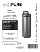
17"
21"
48"
41-1/2"
IN - OUT
34"
3-3/4"
INOUT
FRONT VIEW SIDE VIEW
IN - OUT
41-1/2”
48”
34”
21”
17”
3-3/4”
OUT IN
FRONT VIEW SIDE VIEW
Figure 1
Dimensions
PERFORMANCE CLAIMS
Contaminant Influent Challenge Level Maximum Allowable
Product Water Level
Barium 10 ±10% mg/L 2.0 mg/L
Radium 226/228 25 pCi/L 5 pCi/L
Substance Influent Challenge Level Reduction Requirement
Chlorine 2.0 ±10% mg/L 50%
NOTE: Due to variances in production
and assembly, the Kenmore water
softener valve height may vary by
up to 1/2” from an existing water
treatment system, including existing
Kenmore models. This potential
change in valve height will not
affect system performance.

6
Questions? Visit www.kenmorewatersolutions.com or call 1-800-695-2761.
Packing List
The parts required to assemble and install the water
softener are included with the unit. Thoroughly check
the water softener for possible shipping damage and
parts loss. Also inspect and note any damage to the
shipping carton.
Remove and discard (or recycle) all packing materials.
To avoid loss of small parts, we suggest you keep the
small parts in the parts bag until you are ready to use
them.
Small Parts
Plan Your Installation
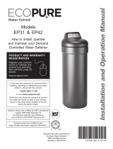
THE PROPER ORDER TO INSTALL WATER TREATMENT EQUIPMENT
(Shows sequence of equipment only - not all items are needed in all applications)
Hybrid
Water
Softener
Sediment
Cartridge
Filter
Water
Heater
Untreated Water to
Outside Faucets
Hot Water
to House
Cold Water
to House
Iron
Filter
Pressure
Tank
City Water Supply
Well Water Supply
Well
Pump
OR
Figure 3
=Always locate an Iron Filter UPSTREAM of the Hybrid Water Softener.
Drain HoseBypass Valve
Adaptor Elbow
Installation
Adaptors
Hose Clamps
Figure 2
O-rings
Grommet
Cover Lock
(for shipping only)
Rim Insert
(for shipping only)
Clips
(2 shipped
installed on the
softener’s valve)

7
Questions? Visit www.kenmorewatersolutions.com or call 1-800-695-2761.
Plan Your Installation
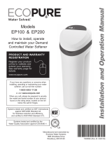
TYPICAL INSTALLATION
5. Do not install in a place where the softener could
freeze. Damage caused by freezing voids the war-
ranty.
6. Put the softener in a place where water damage is
least likely to occur if it develops a leak. Kenmore
or the manufacturer will not repair or pay for water
damage.
7. A grounded, 120V, 60 Hz electrical outlet is needed
near the softener to plug in the power supply (See
Fig. 4). Be sure the outlet and power supply are in
an inside location, protected from wet weather. Use
a continuously “live” outlet, which cannot be acci-
dentally switched off.
8. When installing in an outside location, you must take
the steps necessary to assure the softener, installation
plumbing, and wiring, are protected from the ele-
ments, direct sunlight, contamination, vandalism, etc.
Water
Heater
Hybrid
Water
Softener
Outside Faucet
(hard water) Outside Faucet
(hard water)
Soft, cold water)
Soft, hot water
Figure 4
WHERE TO INSTALL THE HYBRID WATER
SOFTENER
Review the following points before you choose a place
to put your softener:
1. Place as close as possible to, but always downstream
from, the pressure tank (well water) or water meter
(city water).
2. Place as close as possible to a water drain such as a
floor drain, laundry tub, sump or standpipe (See Fig. 4).
3. Connect to the house main water pipe UPSTREAM
OF THE WATER HEATER (See Fig. 3). The tempera-
ture of water going through the softener must not be
more than 100°F (38°C). Hot water will damage
inner softener parts. To reduce the risk of hot water
backup, piping between the softener and water
heater should be as long as possible.
4. Keep outside faucets on hard water to save soft
water and salt. See Fig. 4.
to R.O. Faucet
1-1/2”
Air Gap
Floor
Drain
Main
Shutoff
Valve
R.O.
Storage
Tank
Reverse
Osmosis
System
Hard
Water
to
House
R.O. Drain
Soft Water
to R.O.
System
Water
Meter
Shutoff
Valve
Soft Water Line
Hard Water Line
Grounding wire must
connect metal pipes
120V,
60 Hz

8
Questions? Visit www.kenmorewatersolutions.com or call 1-800-695-2761.
Plan Your Installation
psi, buy and install a pressure reducing valve in the
pipe supplying water to the softener’s inlet.
NOTE: If water pressure during the day is 100 psi or
more, pressure during the night may go above
125 psi.
Installation
For your water softener to work properly, incoming
water pressure in your house pipes must be no lower
than 20 pounds per square inch (psi). The highest
allowable pressure is 125 psi. If pressure is above 125
CHECK YOUR WATER PRESSURE BEFORE INSTALLING
5. Visually check and remove any foreign mate-
rials from the valve inlet and outlet ports (see
Fig. 6). Carefully remove the two large plastic
clips (you will use them). Check to be sure
the turbine and support are firmly in place
(see Fig. 7).
NOTE: If you will not install the included bypass
valve because you will have a 3-valve
bypass in your plumbing, skip step 6, but
perform step 7.
Complete the following steps to assemble the adaptors
and/or the included single bypass valve.
1. Close the shutoff valve on the house main water pipe,
near the water meter or pressure tank, to turn off the
water.
2. Shut off the gas or electric supply to the water
heater.
3. Open the highest and lowest water faucets in your
house. This will let water drain from the pipes.
Close faucets after water has drained.
4. Remove the top cover. Pull outward on the two tabs
to release top cover (see Fig. 5). The salt lid remains
attached to the top cover when removed. Set both
covers aside so they will not get scratched or broken.
INSTALL SINGLE BYPASS VALVE AND/OR THREADED INSTALLATION ADAPTORS
SINGLE BYPASS VALVE:
6. Lightly coat the o-rings with silicone grease and slide
them onto the bypass valve. Push the bypass valve
into the softener valve’s inlet and outlet ports as far
as it will go. Snap the two large holding clips into
place, from the top down as shown (see Fig. 8).
CAUTION: Be sure the clips snap firmly into place so
the bypass valve will not pull out.
INLET AND OUTLET THREADED ADAPTORS:
7. Lightly coat the o-rings with silicone grease and slide
them onto the installation adaptors. Push the adap-
tors into the valve inlet and outlet ports, or bypass
valve ports, as far as they will go. Both adaptors are
the same and fit either port. Snap the two large
holding clips into place, as shown (see Fig. 8).
CAUTION: Be sure the clips snap firmly into place so
the adaptors will not pull out.
Salt Lid
Top Cover
Figure 5
Single
Bypass Valve
Figure 6
Clips
Threaded
Installation
Adaptors
Valve
Outlet
Valve Inlet
Clip
O-Rings
O-Rings
Clip

9
Questions? Visit www.kenmorewatersolutions.com or call 1-800-695-2761.
Installation
INSTALL SINGLE BYPASS VALVE (cont.)
Before installing the bypass valve and/or installation
adaptors, make sure that the turbine and support are
firmly in place inside the softener valve’s outlet port.
ASSEMBLE INLET AND OUTLET PLUMBING
Measure, cut (thread if needed) and put together all
pipe and fittings up to the main water pipe. Make sure
that the incoming water supply pipe goes to the valve
inlet side.
CAUTION: Never solder fittings while connected to
nonmetallic parts. Wait until soldered pipe
has cooled before connection. See Fig. 10.
CAUTION: Be careful when putting pipe fittings togeth-
er. Do not cross thread, and do not over-
tighten.
Figure 7
Turbine
Support
Valve Outlet Turbine
Figure 8
INSTALL HOLDING CLIPS
Bypass Valve or
Installation Adaptor
Plastic Clip
O-Ring
Valve Inlet or Outlet
Plastic clip snaps
into groove in
bypass or adaptor
ALTERNATE BYPASS VALVE INSTALLATION
Figure 9
IN OUT
If connecting to floor
level plumbing, install
the bypass valve turned
downward, as shown.
Figure 10
Incoming
Hard
Water
Main Water Pipe
1. Cut pipe to
correct length
2. Solder. When
cool, do step 3.
3. Put threaded
adaptor into
bypass valve
port.
4. Solder.
NOTE: To be certain
that heat will not
travel down the pipe
and into the bypass
valve or installation
adaptors, wrap the
bottom of the pipe
and the bypass valve
with a wet rag.
IN
Clip
O-Ring

10
Questions? Visit www.kenmorewatersolutions.com or call 1-800-695-2761.
Installation
CONNECT THE VALVE DRAIN HOSE
Take a length of 3/8” inside diameter drain tubing
(supplied) and attach one end to the drain fitting (see
Fig. 11). Use a tube clamp from the parts bag to hold it
in place. Put the other end of the tubing over a floor
drain, into a laundry tub, standpipe, or other suitable
drain. Check your local codes.
Leave an air gap of about 1-1/ 2'' between the end of
the hose and the drain. This gap is needed so you
don’t get a backflow of sewer water into the softener.
Do not put the end of the hose into the drain or con-
nect without the air gap.
Locate and support the hose so it does not kink or have
sharp bends. Secure the hose end so water pressure
does not cause the hose to “whip”. Tie or wire it in
place. Do not pinch the hose shut. The softener will
not work if this drain hose is pinched, plugged, closed
or restricted in any way. Direct drain flow down into
drain from drain line as flow could possibly overshoot
the drain cover.
Keep the hose lower than the drain fitting. In some
homes, to get to a drain you must raise the hose and
run it overhead. Do not raise the hose more than 8 feet
above the floor.
COPPER DRAIN TUBE: Local plumbing codes may
require the use a copper valve drain tube. A copper
tube is also best to use if running a drain line overhead.
To adapt a copper drain tube to the softener, purchase
a compression fitting (1/4'' female pipe threads x 1/2''
O.D. tube) and tubing from your local hardware store.
CONNECT SALT TANK OVERFLOW HOSE
1. Locate the rubber grommet, adaptor elbow and tube
clamp (see Fig. 11) that are in the parts bag.
2. Push the grommet into the hole in the salt tank wall
so that half is inside and half is outside.
3. Push the larger end of the adaptor into the grommet.
4. Push one end of a length of 3/8'' I.D. tubing (sup-
plied) onto the tube adaptor, using a tube clamp
from the parts bag to hold it in place.
5. Put the other end of the tubing over the floor drain.
IMPORTANT: Overflow water must run down by gravity
through the tubing. Do not raise the tub-
ing higher than the adaptor (see Fig. 11).
IMPORTANT: Do not connect this hose to the valve
drain hose you just installed (see above).
Both drains must have a separate hose.
Figure 11
LAUNDRY TUB
Valve
Drain Hose
Salt Tank
Overflow Hose FLOOR DRAIN
STANDPIPE
1-1/2”
Air Gap
1-1/2”
Air Gap
1-1/2”
Air Gap
Tie or wire
tubing in
place
To drain
point other
than floor
drain.
Support tub-
ing in place
as needed.
Tube
Clamp
Tube
Adaptor
Grommet
NOTE: Drain Hose
(12 ft.) is included.
See also parts list.
Drain
Fitting
Tube
Clamp
SUBSTITUTING RIGID DRAIN LINE
Clip
Barbs
1/4 NPT
Threads Compression Fitting, 1/4 NPT x
1/2” O.D. Tube (not supplied)
1/2” Outside
Diameter Copper
Tube (not supplied)
Cut barbs from drain fit-
ting (pull clip and remove
fitting from valve)

11
Questions? Visit www.kenmorewatersolutions.com or call 1-800-695-2761.
Installation
METAL WATER PIPE GROUNDING
IMPORTANT: This water softener has a non-metallic
valve system. Installing it on metal
plumbing will break electrical continuity,
which may interrupt grounding for the
home. You must restore electrical conti-
nuity in your metal plumbing system.
If you installed a 3-valve bypass system (Fig. 14), elec-
trical continuity will be maintained. If you installed the
non-metallic bypass valve (Fig. 13), restore the ground
as follows:
Install a #4 copper wire (parts not included) across the
removed section of metal water pipe, securely clamping
it at both ends (See Fig. 12). Be sure the pipes are
clean under the clamps, to assure good contact.
NOTE: If you are installing a sediment filter or other
item(s) into the plumbing system, along with the
water softener, be sure to restore electrical con-
tinuity across all removed metal pipe sections.
INSTALL COVERS
After installing your water softener, put the covers on.
Angle the covers so the top cover clips onto the back
first, then bring down in front and clip on the tabs
inside the rim and lower the salt lid closed (See Fig. 4).
ADD WATER AND SALT TO THE SALT STOR-
AGE TANK
1. Using a container, add about three gallons of clean
water into the salt storage tank.
2. Add salt to the storage tank. Use nugget, pellet or
coarse solar salts with less than 1% impurities.
CONNECT TO ELECTRICAL POWER
The softener works on 24V DC electrical power. The
included power supply converts 120V AC household
power to 24V DC. Plug the water softener’s power sup-
ply into a grounded, 120V, 60 Hz electrical outlet. Be
sure the outlet is always “live” so it cannot be switched
off by mistake.
NOTE: The electrical outlet you plug the power supply
into must be indoors, protected from weather.
RINSE OUT CARBON FINES
Small particles of carbon filtration material are gener-
ated during manufacturing and shipping, which will exit
the media tank with the first water flow. These carbon
“fines” are not harmful, but give the water a gray color
and should be rinsed down the drain before any water
from the softener is directed to the home’s faucets or
water heater.
CAUTION: To avoid water or air pressure damage to
soft ener inner parts, and to flush pipe chips
or other residue from the water pipes, be
sure to do the following steps exactly as
instructed.
1. Make sure the softener’s valve drain hose is hooked
up and the open end directed to a floor drain, laun-
dry tub or other suitable type of drain.
2. The system should be connected to electrical power.
3. Place bypass valve(s) in “bypass” position (see
Figures 13 & 14). On a single valve, slide the stem
inward to bypass. On a 3-valve bypass, close the
inlet and outlet valves and open the bypass valve.
4. Fully open the house main water pipe shutoff valve.
5. Initiate a regeneration by pressing and holding for 3
seconds the REGENERATION button (see Figure 15
on page 13). The valve motor will start running and
the valve will advance to the “Fill” position.
6. After you hear the valve motor stop running (valve in
“Fill” position), press, but do not hold, the REGENER-
ATION button. The valve will advance to the “Brine”
position.
7. After you hear the valve motor stop running (valve in
“Brine” position), press, but do not hold, the REGEN-
ERATION button. The valve will advance to the
“Backwash” position.
METAL PIPE GROUNDING
(parts not included)
Ground Wire
Clamp (2)
Figure 12
continued on the next page

12
Questions? Visit www.kenmorewatersolutions.com or call 1-800-695-2761.
Installation
Figure 14
3-VALVE BYPASS
Bypass
Valve
Inlet
Valve
Outlet
Valve
FOR SERVICE
Close bypass valve.
Open inlet & outlet
valves.
FOR BYPASS
Open bypass valve.
Close inlet & outlet
valves.
Figure 13
SINGLE BYPASS VALVE
Pull stem outward
for Service
Push inward
for Bypass
8. Once the unit is in backwash, place bypass valve(s)
in SERVICE, EXACTLY as follows:
a. Single Bypass Valve: Slowly, slide pull the valve
stem outward toward service, pausing several times
to allow the softener to pressurize gradually.
b. 3-Valve Bypass: Fully close the bypass valve and
open the outlet valve. Slowly open the inlet valve,
pausing several times to allow the softener to pres-
surize gradually.
9. Let the softener complete the backwash and fast
rinse cycles (takes about 20 minutes). When the
regeneration ends, the softener’s valve returns to the
service position.
LEAK TEST
To check for leaks, complete the following steps:
1. Fully open two nearby cold water faucets down-
stream from the softener.
2. Observe steady weater flow from both open faucets.
3After about three minutes, open a hot water faucet
for about one minute, or until all air is expelled, then
close.
4. Close both cold water faucets.
5. Check your plumbing work for leaks, and fix right
away if any are found. Be sure to observe previous
caution notes.
NOTE: If this procedure is performed on a new softener,
water coming from the taps may initially be dis-
colored. This normally occurs the first time
water runs through the resin bed. The discol-
ored water is not harmful, and the discoloration
will not last more than a few minutes.
RESTART THE WATER HEATER
Turn on the gas (or electric) supply to the water heater
and light the pilot.
YOUR PLUMBING INSTALLATION AND
ELECTRICAL WORK ARE NOW COMPLETE.
continued from the previous page

13
Questions? Visit www.kenmorewatersolutions.com or call 1-800-695-2761.
Programming the Softener
STATUS LIGHT
When the Kenmore Elite®Hybrid Water Softener is
connected to electrical power, the status light on the
control panel will be on or flashing, as follows:
=Status light flashing rapidly, with “PRESENT TIME”
shown in the display and the clock flashing slowly -
The present time needs to be set, either during initial
start up or after a long power outage. See “Set
Present Time of Day”, at right.
=Status light flashing slowly, along with the salt level
indicators in the display - The salt monitor system
indicates a low salt level and needs to be set. See
“Salt Monitor System” on Page 17.
=Status light flashing rapidly, with “Err” shown in the
display - The electronic self-diagnostics have detect-
ed a problem. See “Troubleshooting” on Page 22.
=Status light on steady (not flashing) - The system has
power applied and does not require any attention.
PROGRAM THE SOFTENER
When the power supply is plugged into the electrical
outlet, the model code (520) and a test number (exam-
ple: J3.3), are briefly shown in the display. Then the
words “PRESENT TIME” appear and 12:00 PM begins to
flash.
SET PRESENT TIME OF DAY
If the words “PRESENT TIME" do not show in the dis-
play, press the SELECT button a few times until they do.
1. Press the rUP or sDOWN buttons to set the
present time. Up moves the display ahead; down
sets the time back. Be sure AM or PM is correct.
NOTE: Press buttons and quickly release to slowly
advance the display. Hold the buttons down for
fast advance.
2. When the correct time is displayed, press the SELECT
button, and the display will change to show the
“Hardness” screen.
continued on next page
Figure 17
Figure 16
Select
press for tonight
hold for immediate
Salt
Set
Level Use
Water
Figure 15
STATUS LIGHT (see below)
SET SALT LEVEL button DOWN button
WATER USE button
Display UP buttonREGENERATION button SELECT button

14
Questions? Visit www.kenmorewatersolutions.com or call 1-800-695-2761.
1. Press the rUP or sDOWN buttons to set the
hardness of your water supply, in grains per gallon.
The default is 25.
NOTE: If your water supply contains iron, compensate
for it by adding to the water hardness number.
For example, assume your water is 20 gpg hard
and contains 2 ppm iron. Add 5 to the hardness
number for each 1 ppm of iron. In this example,
you would use 30 for your hardness number.
20 gpg hardness
2 ppm iron x 5 = 10 +10
(times) 30 HARDNESS NUMBER
2. When finished setting your water’s hardness number,
press the SELECT button, and the display will change
to show the “Recharge Time” screen.
Figure 18
Figure 19
Figure 20
Figure 21
Programming the Softener
SET WATER HARDNESS NUMBER
If you completed the previous step, the word “HARD-
NESS" should show in the display. Otherwise, press the
SELECT button several times until it does.
If you completed the previous step, the words “RE -
CHARGE TIME" should show in the display. Otherwise,
press the SELECT button several times until they do.
1. The softener’s default recharge start time is 2:00 AM.
This is normally a time of day when water is not
being used in the household. Hard water bypasses
the softener if the household draws water during the
recharge cycle. If a different recharge start time is
desired, press the rUP or sDOWN buttons to
change the time, in 1-hour increments. Be sure AM or
PM is correct.
2. When the desired recharge start time is displayed,
press the SELECT button, and the display will change
to show one of the “Salt Type” screens shown below.
SET RECHARGE (REGENERATION) START TIME
SET SALT TYPE
If you completed the previous step, either “NaCl” (for
Sodium Chloride) or “KCl” (for Potassium Chloride)
should show in the display. Otherwise, press the
SELECT button several times until one of them does.
1. Press the rUP or sDOWN buttons to set the type
of salt you will be using in your water softener. The
default is NaCl (standard Sodium Chloride water sof-
tener salt). If you will be using KCl (Potassium
Chloride) instead, be sure to set salt type to KCl. This
setting adjusts the regeneration cycle times to com-
pensate for the different rate at which KCl dissolves.
See also the following page for more information on
salt types.
2. When the correct salt type is displayed, press the
SELECT button, and the display will return to the nor-
mal run (time of day) screen.

15
Questions? Visit www.kenmorewatersolutions.com or call 1-800-695-2761.
Adding Salt to the Storage Tank
ADDING SALT TO THE STORAGE TANK
You must keep salt in the tank, but it is not necessary to
fill it full. Especially in humid areas, it is best to fill the
storage tank no more than half full, and to add salt
more often. Salt “bridging” occurs more often when
conditions are humid.
Use NUGGET or PELLET water softener salt. DO NOT
use rock salts, as they have dirt and sediments that will
stop the softener from working. To maintain optimum
performance of your water softener, the salt tank
should be cleaned out every 2 to 3 years.
POTASSIUM CHLORIDE (KCl) SALT
If you choose Potassium Chloride (KCl) as a regenerant,
following these suggestions will help give you years of
maintenance free service.
1. Place only one bag of KCl in your softener at a time
(the salt storage tank should contain no more than
60 pounds of KCl at any one time).
2. A softener using KCl should not be placed in areas
with temperature fluctuations and high humidity (KCl
will harden in these environments and may make the
softener inoperable).
3. Check the brine tank and brinewell (black tube in
salt storage tank) monthly. If hardening is present,
pour small amounts of warm water onto hardened
areas until they loosen.
4. Be sure to set “Salt Type” on the controller to “KCl”.
This setting adjusts the regeneration cycle times to
compensate for the different rate at which KCl dis-
solves. See “Set Salt Type” on the previous page.
Persons who are on sodium restricted diets should con-
sider the added sodium as part of their overall sodium
intake. For example, if your water supply is 15 grains
hard, and you drank 3 quarts of softened water you
would consume 335 milligrams of sodium. That is
equivalent to eating 2-1/2 slices of white bread.
WATER SOFTENING SALT WITH IRON
REMOVING ADDITIVES
Some salts have an additive to help the softener handle
iron in the water supply. These salts may be used if
your water supply has a high iron con tent.
Sanitizing the Softener
SANITIZE THE WATER SOFTENER
1. Open salt lid, remove the brinewell cover and pour
about 3 oz. (6 tablespoons) of household bleach into
the softener brinewell. Replace the brinewell cover.
2. Make sure the bypass valve(s) is in the “service”
(open) position.
3. Start a recharge: Press the REGENERATION button
and hold for 3 seconds, until “RECHARGE”, “Serv”
and “Fill” begin to flash in the display. This recharge
draws the sanitizing bleach into and through the
water softener. Any air remaining in the unit is
purged to the drain.
4. After the recharge has completed, fully open a cold
water faucet, downstream from the softener, and
allow 50 gallons of water to pass through the system.
This should take at least 20 minutes. Close the faucet.
Your new Kenmore Elite®softener is now softening the
water for your household needs. However, your WATER
HEATER is filled with hard water. To have fully soft
water right away, you can drain the water heater so it
refills with soft water. If you don’t drain the water
heater, it will take a few days before you have fully soft
water.
NOTE: If this procedure is performed on a new softener,
water coming from the taps may initially be dis-
colored. This normally occurs the first time water
runs through the resin bed. The discolored water
is not harmful, and the discoloration will not last
more than a few minutes.

16
Questions? Visit www.kenmorewatersolutions.com or call 1-800-695-2761.
What Your Hybrid Water Softener Will Do
The Kenmore Elite®Hybrid Water Softener has been
designed to include two different types of media, a
high quality media that reduces tastes and odors and a
high efficiency media to remove hardness minerals.
This Hybrid Water Softener will provide you and your
home all the benefits of soft water, while providing
whole home chlorine taste and odor reduction and bar-
ium and radium 226/228 reduction. You can have fil-
tered water from your kitchen faucet for food prepara-
tion and drink, in the bath and shower which will
reduce chlorine’s aesthetic effect on your skin and hair,
and at every bathroom sink for brushing your teeth.
There are no filters to change.
Based on NSF-tested rated capacity under NSF/ANSI
Standard 42*, the Kenmore Elite®Hybrid Water
Softener has an estimated useful life for chlorine taste
and odor reduction of over 10 years.
*NSF rated capacity is 570,000 gallons.
Controller Features
EXTRA RECHARGE
Sometimes, a manually initiated recharge (regeneration)
may be desired, or needed. Two examples are:
=You have used more water than usual (guests visiting)
and you may run out of soft water before the next
automatic regeneration.
=You did not add salt to the softener before it ran out.
Add salt to the softener before regenerating.
You can start a regeneration immediately, or you can
set the controller to regenerate at the next preset
recharge time (2:00 AM, or as set).
RECHARGE NOW
Press the REGENERATION button and hold for 3 sec-
onds, until the words “RECHARGE”, “Serv” and “Fill”
begin to flash in the display. The softener enters the fill
cycle of regeneration immediately. This regeneration
will take about 2 hours to complete. Then, you will
have soft water again.
NOTE: If the “Clean Feature” is set ON, the normal
regeneration cycle is preceded by a cleaning
backwash and rinse. The words “CLEAN” and
“Bkwsh” or “Rinse” flash in the display, along
with the minutes of the clean cycle remaining.
RECHARGE TONIGHT
Press and release (do not hold) the REGENERATION
button. “RECHARGE TONIGHT” will begin flashing in
the display, and the softener will begin regeneration at
the next preset recharge time (2:00 AM, or as set). If
you decide to cancel the regeneration before it starts,
press and release the REGENERATION button once
more. “RECHARGE TONIGHT” will stop flashing in the
display.
Figure 22
Figure 23

17
Questions? Visit www.kenmorewatersolutions.com or call 1-800-695-2761.
Controller Features
Figure 26
OPTIONAL SETTINGS:
=SALT EFFICIENCY
=CLEAN FEATURE
=CLEAN FEATURE MINUTES
=97% FEATURE
=12 / 24 HOUR CLOCK
=GALLONS / LITERS
=MAXIMUM DAYS BETWEEN REGENERA-
TIONS
=BACKWASH & FAST RINSE TIMES
1. To set any of these options, press and hold SELECT
for 3 seconds until “000” shows in the display. Then
press (do not hold) SELECT again to display one of
the “Salt Efficiency” screens shown below.
SALT EFFICIENCY: When this feature is ON, the
water softener will operate at salt efficiencies of
4000 grains of hardness per pound of salt or higher.
The softener may recharge more often using smaller
salt dosage and less water. This softener is shipped
with the efficiency feature set OFF. Installations in
the State of California require this setting to be
turned ON. Use the rUP or sDOWN buttons to
change between OFF and ON.
California Efficiency Requirement
Your Kenmore Elite®Water Softener has a “High
Efficiency” feature that can be set ON or OFF.
This softener is shipped with the efficiency feature
set OFF, which will utilize the maximum rated
capacity while most often achieving maximum salt
efficiencies. When installing this unit in the State
of California, you MUST turn the efficiency feature
ON. The softener may initiate more frequent
recharges, but it will operate at 4000 grains per
pound of salt or higher.
Efficiency Icon
LEVEL
SALT
Figure 25
press for tonight
hold for immediate
Salt
Set
Level
L
Figure 24
3. Press the SET SALT LEVEL button as many times as
necessary to make the salt level bars in the display
(see Fig. 24) match the number on the brinewell. At
level 2 or below, the “Low Salt" indicator will flash.
4. If you want to turn the salt monitor off, press the SET
SALT LEVEL button past 8, until “OFF” shows in the
display next to the number 8.
SALT MONITOR SYSTEM
The water softener has a salt monitor indicator light to
remind you to add salt to the storage tank.
NOTE: You must set salt level each time salt is added
to the water softener.
NOTE: The salt monitor system estimates salt levels, and
accuracy will vary with different salts.
To set this monitor system:
1. Lift the salt lid and level the salt in the storage tank.
2. The salt level scale, on the brinewell inside the tank,
has numbers from 0 to 8 (see Fig. 24). Observe the
highest number the leveled salt is at, or closest to.
Salt
Level
Numbers
Brinewell
Salt Level
Bars

18
Questions? Visit www.kenmorewatersolutions.com or call 1-800-695-2761.
Controller Features
Figure 28
Figure 27
2. Press SELECT again to display one of the “Clean”
screens shown below.
CLEAN: This feature is beneficial on water supplies
containing iron and/or high amounts of sediments
(sand, silt, dirt, etc.). When set to ON, a backwash
and fast rinse cycle will occur first, preceding the
normal regeneration sequence. This provides extra
cleaning of the resin bed before it is regenerated
with the salt brine. To conserve water, if your water
supply does not contain iron or sediments, be sure
this feature is set to OFF. The default is OFF. Use
the rUP or sDOWN buttons to change between
OFF and ON.
3. Press SELECT again to display the “Clean Time”
screen shown below.
CLEAN FEATURE MINUTES: If you have set the
Clean Feature ON, the length of the extra backwash
cycle auto matically is set to 2 minutes. However, you
can ad just this time from 1 to 15 minutes in length.
To change this cycle time, use the rUP button to
increase the time, or the sDOWN button to short-
en the time. If no change is desired, continue to next
step.
Figure 30
Figure 29
4. Press SELECT again to display the “97%” screen.
97% FEATURE: The 97% Feature can save salt and
water by regenerating when 97% of the softener’s
capacity has been used up. With this feature ON,
the regeneration can occur at any time (whenever
the system has reached 97% of its capacity). The
default is OFF. If this feature is desired, turn it on by
pressing the rUP button.
5. Press SELECT again to display the “12 or 24 hr”
screen.
12 OR 24 HOUR CLOCK: All time displays are shown
in standard clock time (1 to 12 AM; and 1 to 12 PM)
at the 12 hr default setting. If 24 hour time format is
desired, set to 24 hr by pressing the rUP button.

19
Questions? Visit www.kenmorewatersolutions.com or call 1-800-695-2761.
Figure 31
Figure 32
6. Press SELECT again to display the “Gallons or Liters”
screen.
GALLON OR LITER READINGS: Water usage and
flow rate displays are shown in gallons at the default
setting. If you prefer liters, change this setting from
“Gals” to “Liter” by pressing the rUP button.
7. Press SELECT again to display the “Recharge Days”
screen.
MAXIMUM DAYS BETWEEN REGENERATIONS: The
electronic controller automatically determines regen-
eration fre quency. This provides the greatest operat-
ing efficiency and, under most conditions this feature
will be left in its default mode. However, you can set
this feature to force a regeneration every set number
of days. You may want to do this if, for exam ple,
your water supply contains iron and you want the
softener to regenerate at least once every few days
to keep the resin bed clean. Use the rUP or s
DOWN buttons to change the number of days (up to
15). If no change is desired, continue to next step.
Controller Features
8. Press SELECT again to display the “Backwash Time”
setting screen.
Figure 33
BACKWASH & FAST RINSE TIMES: If you experience
salty tasting water after regeneration, you may need
to increase the backwash and fast rinse times. The
default backwash time is 13 minutes and the default
fast rinse time is 6 minutes. However, you may
increase or decrease the backwash and fast rinse
times, in 1 minute increments.
If you wish to change the backwash time, use the r
UP or sDOWN buttons to set the backwash time
between 1 and 30 minutes. Then press SELECT to
display the “Fast Rinse Time” setting screen.
Figure 34
If you wish to change the fast rinse time, use the
rUP or sDOWN buttons to set the fast rinse
time between 1 and 30 minutes.
9. Press SELECT to return to the normal run (time of
day) screen.
TANK LIGHT
A light inside the salt storage tank will come on when-
ever you open the salt lid. A “Tank Light” icon is dis-
played when this light is on. The light turns off when
you close the salt lid. It will also turn off automatically
after 15 minutes if the salt lid is left open.
Figure 35
Tank Light
Icon
Figure 35
Tank Light
Icon

20
Questions? Visit www.kenmorewatersolutions.com or call 1-800-695-2761.
Controller Features
Figure 36
Figure 37
Figure 38
Figure 39
Top
Distributor
Ultra Cleansing Screen
Resin
Tank
AVERAGE DAILY GALLONS OR LITERS
Press the WATER USE button a second time to display
the average number of gallons (or liters) of soft water
that the household uses each day. This water usage
figure is recalculated daily by the elctronic controller.
To turn this display off, press the WATER USE button
once again.
WATER FLOW THROUGH THE SOFTENER
To view the flow rate through the softener in gallons (or
liters) per minute, press the WATER USE button. If soft
water is in use, the flow rate will be displayed to the
nearest tenth of a gallon (or liter). The display will
show “0” when all faucets and water using appliances
are off.
RECHARGE TIME REMAINING & VALVE
POSITION INDICATORS
One of the valve position indicators (Serv, Fill, Brine,
Bkwsh, Rinse) is displayed while the softener is recharg -
ing. RECHARGE flashes in the display and, beginning
with Brine, the minutes of recharge remaining before
return to service appears in place of the present time.
When the valve is moving from one cycle to another,
both position indica tors are flashing.
PROGRAM MEMORY
If electrical power to the softener goes off, the time dis-
play is blank but the electronic controller keeps the cor-
rect time for several hours. When electrical power
comes on again, you will have to reset the present time
only if the display is flashing. The HARDNESS and
RECHARGE TIME never require resetting unless a
change is desired. Even if the clock is incorrect after a
long power outage, the softener works as it should to
keep your water soft, however, regenerations may occur
at the wrong time of day until you reset the clock to the
correct time of day.
KENMORE’S ULTRA CLEANSING FEATURE
The ultra cleansing feature keeps larger particles of
sediment from entering the home’s plumbing system. As
water passes through the softener, the larger sediment
particles are collected in the integrated basket and
then rinsed to the drain before each regeneration. The
ultra cleansing feature provides added protection for
water using appliances by reducing the chance of larg-
er particles entering the various products valves and
screens. The “Clean Feature” may be turned ON to
provide an extra backwash that will help keep the ultra
cleansing screen clean. The default is OFF.
IMPORTANT: The ultra cleansing feature is not intended
to replace pretreatment filtration. For
problem water applications, additional
sediment filtration is recommended.
Page is loading ...
Page is loading ...
Page is loading ...
Page is loading ...
Page is loading ...
Page is loading ...
Page is loading ...
Page is loading ...
Page is loading ...
-
 1
1
-
 2
2
-
 3
3
-
 4
4
-
 5
5
-
 6
6
-
 7
7
-
 8
8
-
 9
9
-
 10
10
-
 11
11
-
 12
12
-
 13
13
-
 14
14
-
 15
15
-
 16
16
-
 17
17
-
 18
18
-
 19
19
-
 20
20
-
 21
21
-
 22
22
-
 23
23
-
 24
24
-
 25
25
-
 26
26
-
 27
27
-
 28
28
-
 29
29


Ask a question and I''ll find the answer in the document
Finding information in a document is now easier with AI
Related papers
-
Kenmore 625.383500 User guide
-
Sears Kenmore Elite 596.7857*800 User manual
-
-
Kenmore Elite 38620 Owner's manual
-
-
-
Kenmore High-Efficiency Water Softener Owner's manual
-
-
-
Other documents
-
EcoWater EP6130 & EP6225 Owner's manual
-
 ECOPURE EP7130 Owner's manual
-
Eco Pure NSC42 Specification
-
 ECOPURE EP31 Installation guide
-
North Star NSC42 Installation guide
-
-
 ECOPURE EP31 Owner's manual
-
 ECOPURE EP200 Owner's manual
-
Whirlpool WHES40 User guide
-
Whirlpool WHES48 User manual


