Garmin STRIKER™ Plus 5cv with Transducer Installation guide
- Type
- Installation guide

Garmin ClearVü
Transducer Transom/
Trolling Motor Mount
Installation Instructions
Important Safety Information
WARNING
See the Important Safety and Product Information guide in the
chartplotter or fishfinder product box for product warnings and
other important information.
You are responsible for the safe and prudent operation of your
vessel. Sonar is a tool that enhances your awareness of the
water beneath your boat. It does not relieve you of the
responsibility of observing the water around your boat as you
navigate.
CAUTION
Failure to install and maintain this equipment in accordance with
these instructions could result in damage or injury.
Always wear safety goggles, ear protection, and a dust mask
when drilling, cutting, or sanding.
NOTICE
When drilling or cutting, always check what is on the opposite
side of the surface.
This equipment should be installed by a qualified marine
installer.
To obtain the best performance and to avoid damage to your
boat, you must install the Garmin® device according to these
instructions.
Read all installation instructions before proceeding with the
installation. If you experience difficulty during the installation,
contact Garmin Product Support.
Tools Needed
• Drill and drill bits
• Number 2 Phillips screwdriver
• Masking tape
• Marine sealant
Preparing the Transducer for Long-Term Exposure to
Water
NOTICE
Do not use acetone or acetone-based products on the
transducer. Acetone damages the plastic transducer housing.
When you install a transducer on a boat that spends a
significant amount of time in the water, you should coat the
transducer and mounting hardware with a water-based anti-
fouling paint to prevent marine growth.
1Lightly sand the transducer and mounting hardware with a
fine-grit abrasive pad.
2Wipe the transducer and mounting hardware with isopropyl
alcohol.
3Apply water-based anti-fouling paint to the transducer and
mounting hardware.
Mounting Consideration
To ensure peak performance with the lowest noise and
interference, you should route the transducer cable away from
ignition wires, house batteries and wires, trolling motor batteries
and wires, and high-energy wires such as radar, audio amplifier,
and autopilot pump wires.
Installing the Transducer on a Transom
Mounting Location Considerations
• The transducer should be mounted parallel to the water line.
• The transducer should be mounted as close to the center of
the boat as possible.
• If your propeller moves clockwise when the boat moves, the
transducer should be mounted on the starboard side.
• If your propeller moves counter-clockwise when the boat
moves, the transducer should be mounted on the port side.
• The transducer should not be mounted behind strakes, struts,
fittings, water intake or discharge ports, or anything that
creates air bubbles or causes the water to become turbulent.
The transducer must be in clean (non-turbulent) water for
optimal performance.
• The transducer should not be mounted in a location where it
might be jarred when launching, hauling, or storing.
• On single-drive boats, the transducer must not be mounted in
the path of the propeller.
The transducer can cause cavitation that can degrade the
performance of the boat and damage the propeller.
• On boats with outboard or inboard/outboard motors, the
transducer should be mounted at least 38 cm (15 in.) from
the propeller.
• On twin-drive boats, the transducer should be mounted
between the drives, if possible.
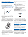
Assembling the Transducer with a Transom Mount
Bracket
1Attach the mount À to the transducer Á with the included
star washers Â, and screws Ã.
2Attach the mount to the bracket Ä with the bolt Å, rubber
washer Æ, flat washer Ç, and lock nut È.
NOTE: The bolt should be tight enough to hold the
transducer in place when the boat moves at high speed, but
loose enough to allow the transducer to pivot out of the way if
the transducer hits an obstruction.
February 2017 Printed in Taiwan 190-02116-02_0A

Installing the Transom-Mount Hardware
NOTICE
If you are mounting the bracket on fiberglass with screws, it is
recommended to use a countersink bit to drill a clearance
counterbore through only the top gel-coat layer. This will help to
avoid cracking in the gel-coat layer when the screws are
tightened.
The cables connected to the transducer should not be cut,
because cutting the transducer cables voids your warranty.
1Cut out the template.
2With the template À aligned vertically on the transom at the
installation location (Mounting Consideration, page 1), place
the bottom corner Á of the template on the edge of the
transom.
3Mark the center location of the two holes of the template.
4Remove the template from the transom.
5Wrap a piece of tape around a 4 mm (5/32 in.) bit at 18 mm
(7/10 in.) from the point of the bit, to avoid drilling the pilot
holes too deep.
6If you are installing the bracket on fiberglass, place a piece of
tape over the pilot-hole location to reduce cracking of the gel
coat.
7Using the 4 mm (5/32 in.) bit, drill the pilot holes approximately
18 mm (7/10 in.) deep at the marked locations.
8Apply marine sealant to the included 20 mm screws, and
attach the transducer assembly to the transom.
9Route the cable under the transom mount cable hook.
10If you must route the cable through the transom, choose a
pilot-hole location well above the waterline and mark it.
11Place a cable clamp on the transducer cable, approximately
halfway between the transducer and the top of the transom or
the pass-through pilot hole.
12Mark the pilot-hole location for the cable clamp, and using a
3.2 mm (1/8 in.) bit, drill a pilot hole approximately 10 mm
(3/8 in.) deep.
13Apply marine sealant to the included 12 mm screw, and
attach the cable clamp to the transom.
14If you marked a pilot hole in step 7, choose the appropriate
drill bit to drill a pass-through hole completely through the
transom:
• If you have the 4-pin cable, use a 16 mm (5/8 in.) drill bit.
• If you have the 8-pin cable, use a 25 mm (1 in.) drill bit.
15Route the transducer cable to the sounder:
• If you are routing the cable using a pass-through hole,
push it through the pass-through hole, and install the
cable-entry cover (Installing the Cable-Entry Cover,
page 2).
• If you are not routing the cable using a pass-through hole,
route the cable up and over the top of the transom.
You should avoid routing the cable close to electrical wires or
other sources of electrical interference.
Installing the Cable-Entry Cover
If you routed the cable through the transom after you installed
the transducer, you should install the cable-entry cover to keep
water from entering your boat.
1Place the cable-entry cover À over the hole and the cable,
with the opening pointing downward, and mark the location of
the two pilot holes.
2Remove the cable-entry cover, and, using a 3.2 mm (1/8 in.)
bit, drill the pilot holes approximately 10 mm (3/8 in.) deep.
3Fill the pass-through hole with marine sealant so it covers the
cable completely and there is excess sealant around the hole
and the cable.
4Place the cable-entry cover over the hole and the cable, with
the opening pointing downward.
5Apply marine sealant to the included 12 mm M4 screws, and
attach the cable-entry cover to the transom.
6Wipe away all excess marine sealant.
Testing the Installation
NOTICE
You should check your boat for leaks before you leave it in the
water for an extended period of time.
Because water is necessary to carry the sonar signal, the
transducer must be in the water to work properly. You cannot
get a depth or distance reading when out of the water. When
you place your boat in the water, check for leaks around any
screw holes that were added below the water line.
Testing the Transom-Mount Transducer Installation
NOTICE
When adjusting the depth of the transducer, make the
adjustments in small increments. Placing the transducer too
deep can adversely affect the performance of the boat and put
the transducer at risk of striking underwater objects.
Test the transom-mount transducer installation in open water
free of obstacles. Pay attention to your surroundings as you test
the transducer.
1With the boat in the water, turn on the chartplotter.
2

2Drive the boat at a slow speed. If the chartplotter appears to
be working properly, gradually increase speed while
observing the chartplotter.
3If the sonar signal is suddenly lost or the bottom return is
severely degraded, note the speed at which this occurs.
4Return the boat to the speed at which the signal was lost,
and make moderate turns in both directions while observing
the chartplotter.
5If the signal strength improves while turning, adjust the
transducer so that it extends another 1/8 in. (3 mm) below the
transom of the boat.
6Repeat steps 2–4 until the degradation is eliminated.
7If the signal does not improve, move the transducer to a
different location on the transom, and repeat the test.
Installing the Transducer on a Trolling Motor
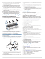
Assembling the Trolling Motor Mount
1Using the 8 mm M4 screws À and 4 mm star washers Á,
attach the trolling motor mount  to the transducer Ã.
2Route the cable through the cable exit Ä so the cable is on
the top side of the trolling motor housing when stowed.
Installing the Transducer on a Trolling Motor
NOTICE
Do not cut the transducer cable. Cutting the transducer cable
will void your warranty.
1Insert the hose clamp À through the slot on the transducer
mount Á, until equal lengths extend on both sides of the
mount.
2Place the transducer mount against the body of the trolling
motor with the narrow end of the transducer pointed away
from the propeller.
3Secure the hose clamp around the body of the trolling motor,
and tighten the hose clamp.
4Position the transducer so it is parallel to the bottom when in
use.
5Use the included cable ties to secure the transducer cable.
6Route the transducer cable to the installation location of the
sounder while taking these precautions.
• The cable should not be routed close to electrical wires or
other sources of electrical interference.
• The cable must not be pinched when the trolling motor is
deployed or stowed.
Software Update
You may need to update the device software when you install
the device or add an accessory to the device.
Loading the New Software on a Memory Card
You must copy the software update to a memory card using a
computer that is running Windows® software.
NOTE: You can contact Garmin customer support to order a
preloaded software update card if you do not have a computer
with Windows software.
1Insert a memory card into the card slot on the computer.
2Go to www.garmin.com/support/software/marine.html.
3Select Download next to the software bundle that
corresponds with your device.
4Read and agree to the terms.
5Select Download.
6If necessary, select Run.
7If necessary, select the drive associated with the memory
card, and select Next > Finish.
Updating the Device Software
Before you can update the software, you must obtain a
software-update memory card or load the latest software onto a
memory card.
1Turn on the chartplotter.
2After the home screen appears, insert the memory card into
the card slot.
NOTE: In order for the software update instructions to
appear, the device must be fully booted before the card is
inserted.
3Follow the on-screen instructions.
4Wait several minutes while the software update process
completes.
5When prompted, leave the memory card in place and restart
the chartplotter manually.
6Remove the memory card.
NOTE: If the memory card is removed before the device
restarts fully, the software update is not complete.
Registering Your Device
Help us better support you by completing our online registration
today.
• Go to my.garmin.com.
• Keep the original sales receipt, or a photocopy, in a safe
place.
Contacting Garmin Product Support
• Go to support.garmin.com for in-country support information.
• In the USA, call 913-397-8200 or 1-800-800-1020.
• In the UK, call 0808 238 0000.
• In Europe, call +44 (0) 870 850 1241.
© 2017 Garmin Ltd. or its subsidiaries
3

Garmin® and the Garmin logo are trademarks of Garmin Ltd. or its subsidiaries,
registered in the USA and other countries. These trademarks may not be used without
the express permission of Garmin.
Windows® is a registered trademark of Microsoft Corporation in the United States and
other countries.
© 2017 Garmin Ltd. or its subsidiaries support.garmin.com
-
 1
1
-
 2
2
-
 3
3
-
 4
4


Garmin STRIKER™ Plus 5cv with Transducer Installation guide
- Type
- Installation guide
Ask a question and I''ll find the answer in the document
Finding information in a document is now easier with AI
in other languages
Related papers
-
Garmin Pacote de Transdutores Installation guide
-
Garmin GT34UHD-TM Owner's manual
-
Garmin GT15M-TM Installation guide
-
Garmin GT36UHD-TM Installation guide
-
Garmin 010-11050-10 User manual
-
Garmin GT8HW-TM High Wide CHIRP akterspegelgivare eller trollingmotorgivare i plast (150240kHz, 250W) (8-polig) Installation guide
-
Garmin GLS 10-ekkoloddmodul Installation guide
-
Garmin Panoptix LiveScope LVS12 Transducer Installation guide
-
Garmin GT20_TM Installation guide
-
Garmin Panoptix LiveScope™ System Owner's manual