54677141

Commercial Electric 54677141, WR484040EFL User guide

  • Hello! I am an AI chatbot trained to assist you with the Commercial Electric 54677141 User guide. I’ve already reviewed the document and can help you find the information you need or explain it in simple terms. Just ask your questions, and providing more details will help me assist you more effectively!
  • What should I do if I discover the product is malfunctioning?
    Who handles warranty claims?
    What should be done before starting assembly and installation?
    What are important safety considerations during installation?
    In the absence of a junction box, what alternative installation method can I use?
    How do I connect the fixture's wires to the power supply?
    What is the recommended screw type for securing the fixture to the junction box?
    How do I securely attach the lens to the fixture?
THANK YOU
wrap light. We strive to continually create quality products designed to enhance your home. Visit us online to see our
full line of products available for your home improvement needs. Thank you for choosing Commercial Electric!
USE AND CARE GUIDE
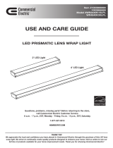
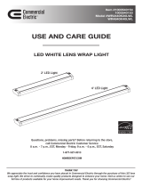
LED LENS WRAP LIGHT
Questions, problems, missing parts? Before returning to the store,
call Commercial Electric Customer Service
8 a.m. - 7 p.m., EST, Monday - Friday, 9 a.m. - 6 p.m., EST, Saturday
1-877-527-0313
HOMEDEPOT.COM
Item #
Model #
2
Table of Contents
Safety Information .....................................................2
Warranty.....................................................................2
Pre-Installation ..........................................................3
Planning Installation ..............................................3
Tools Required .......................................................3
Hardware Included .................................................3
Package Contents ..................................................3
Junction Box Installation ..........................................4
Keyhole Installation ...................................................6
Care and Cleaning .....................................................9
Troubleshooting .........................................................9
Safety Information
WARNING: Carefully read and understand this manual
before beginning the assembly and installation. Failure
which could be hazardous or even fatal.
WARNING: Before beginning the installation,
disconnect the power to the circuit by turning off the
circuit breaker or removing the fuse.
WARNING:
requires a person familiar with the construction and
IMPORTANT:
approved by the party responsible for compliance could
void the user’s authority to operate the equipment.
NOTICE: This equipment has been tested and found to comply with
the limits for a Class B digital device, pursuant to Part 15 of the FCC
Rules. These limits are designed to provide reasonable protection
against harmful interference in a residential installation. This equipment
generates, uses and can radiate radio frequency energy and, if not
installed and used in accordance with the instructions, may cause
harmful interference to radio communications.
However, there is no guarantee that interference will not occur in a
particular installation. If this equipment does cause harmful interference
to radio or television reception, which can be determined by turning
the equipment off and on, the user is encouraged to try to correct the
interference by one or more of the following measures:
FCC responsible party
Precision Consumer Products Group, LLC.
11024 Balboa Boulevard Suite 1710 Granada Hills, CA 91344
1-866-237-9983
Reorient or relocate the receiving antenna.
Increase the separation between the equipment and the receiver.
Connect the equipment into an outlet on a circuit different from
that to which the receiver is connected.
Consult the dealer or an experienced radio/TV technician for help.
Warranty
WHAT IS COVERED
products used in normal use and service. If this product is found to be defective, the manufacturer’s only obligation,
and your exclusive remedy, is the repair or replacement of the product at the manufacturer’s discretion, provided
mishandling.
WHAT IS NOT COVERED
This warranty shall not apply to any product that is found to have been improperly installed, set-up, or used in any
way not in accordance with the instructions supplied with the product. This warranty shall not apply to a failure of
the product as a result of an accident, misuse, abuse, negligence, alteration, faulty installation, or any other failure
product, such as surface and/or weathering, as this is considered normal wear and tear.
liability and shall not be liable for any consequential or incidental loss or damage, including but not limited to any
labor / expense costs involved in the replacement or repair of said product.
Contact the Customer Service Team at 1-877-527-0313 or visit www.HomeDepot.com.
3 HOMEDEPOT.com
Please contact 1-877-527-0313 for further assistance.
Pre-Installation
PLANNING INSTALLATION
Before beginning assembly, installation, or operation of the product, make sure all parts are present. Compare parts
with the package contents list. If any part is missing or damaged, do not attempt to assemble, install, or operate the
product. Contact customer service for replacement parts.
NOTE: Keep your receipt and these instructions for proof of purchase.
installation.
TOOLS REQUIRED
Phillips
screwdriver Ladder Safety
glasses
Wire
strippers
Wire
cutters
Power drill
with drill bits
HARDWARE INCLUDED
Part Description Quantity
AA BB CC DD
AA Phillips head junction box machine screws 2
BB Wire nuts 4
CC Phillips head wood screws 2
DD Dry wall anchors 2
PACKAGE CONTENTS
Part Description Quantity
A Chassis 1
B Lens 1
C Hinged endcap (pre-installed) 1
A
B
C
PULL OUT TO REMOVE!
D Channel cover 1
E Channel cover screws 4
D
E
label
F Knockouts 8
F
4
Pre-Installation (continued)
before drilling.
WARNING: RISK OF ELECTRIC SHOCK. Ensure the electricity to the wires you are working on is shut off. Either remove the fuse or
CAUTION: Before beginning installation turn off the circuit breaker and light switch.
IMPORTANT: Depending on the type and orientation of junction box it may be necessary to use the keyhole installation method on page 6
Junction Box Installation
1 Installing the screws
Install the two screws (AA) into the junction box (1).
NOTE: Leave 3/8" of screw thread exposed to
1
AA
2 Removing the lens and channel cover
Remove the lens (B) from the chassis (A) by
rotating hinged endcap (C) away from the chassis (A)
Hold the hinged endcap outboard and gently lift
and remove the lens (B) from the chassis(A).
Use a Phillips screwdriver to remove channel cover
screws (E) to remove the channel cover
3 Removing the knockout
Use a screwdriver to remove the pre-punched knockout (1) at the center of the chassis (A) and feed
the White, Red, Black and Ground fixture wires through the knockout hole.
A1
C
B
A
DE
5 HOMEDEPOT.com
Please contact 1-877-527-0313 for further assistance.
Junction Box Installation (continued)
4 Wiring the fixture
5Attaching the fixture
Attach the fixture (A) to the junction box by aligning the holes on the fixture (A) with the junction box screws
(AA) installed in the previous step. After aligning screw heads (AA) with mounting slots on fixture, rotate fixture
until properly aligned with room orientation. After properly oriented, tighten screw heads (AA) with a Phillips
screwdriver, ensuring the fixture is secure and will not move.Then use a screwdriver to cover channel cover.
If proper fixture orientation is not possible due to junction box/hole positioning, proceed to step 3 of the Key
Hole Installation method on page 6.
Starting on one side, align the channel cover flange with the locking tabs on the fixture chassis as indicated in
schematic (A1).Slide the flange under the locking tabs and be sure all wires are tucked under the channel cover.
While ensuring flange remains under locking tabs, squeeze the channel cover until the flange on the opposite
side of the channel cover are able to slide under the locking flanges on the opposite side.Once channel cover is
securely in place and all wires are inside the channel cover, replace channel cover screws using a Phillips
screwdriver.
6 Attaching the lens
Carefully slide the end of the lens (B) into the
fixed endcap on the fixture base (A).
While holding the lens, (B) rotate the hinged
endcap (C) outward and ensure the full length of
the lens is now flat against the fixture base (A)
Carefully allow the hinged endcap (C) to rotate
inward until it is resting against the lens (B)
IMPORTANT: Hinged endcap (C) is spring loaded. To
avoid possible damage, do not allow hinged endcap (C)
to snap back against the lens.
A
C
B
A
Ensure 3/8 in. of the wire sheathing is removed
from the end of the black , white , and
green fixture wires in order to expose the copper wires.
Using included wire nuts (BB):
Connect the yellow/green fixture ground wire with
the building power supply ground wire.
Connect the white fixture wire with the white
building power supply wire.
Connect the Red and Black Fixture wires with
the black building supply wire.
After ensuring all wire nut connections are secure,
Gently tuck all wire connections back into the
junction box.
E
BB
Switch
A
A1
6
Keyhole Installation
2 Removing the knockout
3 Positioning the fixture
Position chassis (A) to align the knockout hole with the supply wire location.
Mark these locations
Use a screwdriver to remove the pre-punched knockout (1) at the center of the chassis (A) and feed
the White, Red, Black and Ground fixture wires through the knockout hole.
1 Removing the lens and channel cover
Remove the lens (B) from the chassis (A) by
rotating hinged endcap (C) away from the chassis (A)
Hold the hinged endcap outboard and gently lift
and remove the lens (B) from the chassis(A).
Use a Phillips screwdriver to remove channel cover
screws (E) to remove the channel cover
While holding in place mark the location of the two keyhole slots at each end of the housing on your
mounting surface.
C
B
A
DE
A1
(mounting surface)
7 HOMEDEPOT.com
Please contact 1-877-527-0313 for further assistance.
Keyhole Installation (continued)
4 Mounting the fixture through
drywall
If mounting in drywall without a stud, at the
locations marked in the previous step, drill a
small pilot hole with 1/8" drill bit (not included)
and install wall anchors (DD) into the holes with
a hammer (not included). Install the two wood
screws (CC) into the mounting surface, leaving
an approximate 3/8 in gap between the screw
head and the mounting surface
Drywall
DD
CC
5 Mounting the fixture to a wall
stud
If the mounting holes align with wall studs,
drill a pilot hole using a 5/32" drill bit (not
included) for the wood screws (CC).
Install the two wood screws (CC) into the
mounting surface leaving an approximate
3/8 in gap between the screw head and the
mounting surface.
Wall stud
CC
6 Connecting the wires
Ensure 3/8 in. of the wire sheathing is removed
from the end of the black , white , and
green fixture wires in order to expose the copper wires.
Using included wire nuts (BB):
Connect the yellow/green fixture ground wire with
the building power supply ground wire.
Connect the white fixture wire with the white
building power supply wire.
Connect the Red and Black Fixture wires with
the black building supply wire.
Gently tuck all wire connections back into thejunction box.
After ensuring all wire connections are secure,
gently tuck the wires into the junction box and guide.
Hide the wires in the junction box and guide the
headsof the two wood screws (CC) into the keyhole
slots. slide the fixture (A) so that the wood screw
heads (CC) rest over the narrow part of the keyhole slot.
Ensure that the fixture (A) is supported and tighten the
two wood screws (CC) until the fixture is securedto the
mounting surface.
A
7
Attaching the fixture
CC
BB
Switch
8
Keyhole Installation (continued)
8 Attaching the fixture
9Attaching the lens
IMPORTANT: Hinged endcap (C) is spring loaded. To
avoid possible damage, do not allow hinged endcap (C)
to snap back against the lens
A
C
B
Carefully slide the end of the lens (B) into the fixed endcap on the chassis base (A).
While holding the lens, (B) rotate the hinged endcap (C) outward and ensure the full length of the lens is
now flat against the chassis base (A).
Carefully allow the hinged endcap (C) to rotate inward until it is resting against the lens (B)
10 Replace battery
After turning off the power, refer to Step 2 page 4 to remove lens and channel cover.
Remove the battery with a screwdriver, remove the quick plug cable,
Remove the battery with a Phillips screwdriver. Remove the quick plug cable from the emergency driver.
Once lens and channel cover have been removed, disconnect the battery from the emergency driver via quick connect.
Using a Phillips screwdriver, remove the (2) screws securing the battery to the chassis.
Position the replacement battery and re-attach with the same (2) screws.
Re-connect the battery and emergency driver via quick connects.
Replace channel cover and lens in accordance with steps 5 and 6 on page 5.
The battery specifications are as follows:
The battery type
The battery size
The battery capacity
The battery voltage
LifePo4
130*28*30MM
3000mAh/19.2WH
6.4V
label label
Starting on one side, align the channel cover flange with the locking tabs on the fixture chassis as indicated in
schematic (A1).Slide the flange under the locking tabs and be sure all wires are tucked under the channel cover.
While ensuring flange remains under locking tabs, squeeze the channel cover until the flange on the opposite
side of the channel cover are able to slide under the locking flanges on the opposite side.Once channel cover is
securely in place and all wires are inside the channel cover, replace channel cover screws using a Phillips
screwdriver.
E
A1
9 HOMEDEPOT.com
Please contact 1-877-527-0313 for further assistance.
Care and Cleaning
CAUTION:
the fuse from the fuse box.
Do not use cleaners with chemicals, solvents, or harsh abrasives.
Troubleshooting
WARNING:
Problem Probable Cause Solution
The power is off. Ensure the power supply is on.
The circuit breaker is off. Ensure the circuit breaker is in the on
position.
There is a bad connection. Check to ensure proper wire connections
There is a defective switch.
The fuse blows or the circuit
breaker trips when the light is
turned on.
The wires are crossed or the power
wire is grounding out.
Check the wire connections.
Commercial Electric customer service
1-877-527-0313.
Test switch
Lighting control switch
Mode
Frequency
Power
Hold time
Bightness
Business mode
Home mode
Mounting high
Movement detected 0.5~1M/S
Max4.5(vertical)
5.8GHz +/- 75MHz
<0.3mW
hold 5s (manufacturer test mode)
no sensor function
2min 100% full bright and then hold 25%
2min 100% full bright and then off
Mode
Sleep
Reset
long press test switch > 5s,
mergency power shut down,
again after connect AC power supply,
the system is restarted.
In emergency working, press the
test switch > 3S, and the emergency
power enters sleep mode,
the utility is switched on and reactivated.
Lighting control
switch of sensor
Home mode
Business mode
Hold time
Bightness
Home mode Business modeBightness Hold time
Test switch
Questions, problems, missing parts? Before returning to the store,
call Commercial Electric Customer Service
8 a.m. - 7 p.m., EST, Monday-Friday, 9 a.m. - 6 p.m., EST, Saturday
1-877-527-0313
HOMEDEPOT.COM
Retain this manual for future use.
/