Pottinger EUROCAT 272 Operating instructions
- Category
- Kitchen & houseware accessories
- Type
- Operating instructions
This manual is also suitable for

Operator‘s manual
GB
+ INSTRUCTIONS FOR PRODUCT DELIVERY . . . Page 3
"Translation of the original Operating Manual" Nr.
• Drum mower
99 3672.GB80Q.0
EUROCAT 272
(Type PSM 3672 : + . . 00001)
EUROCAT 272 ED
(Type PSM 3682 : + . . 00001)
EUROCAT 312
(Type PSM 3673 : + . . 00001)

1500_GB-PAGE 2
Product liability, information obligation
Product liability obliges manufacturers and dealers to issue operating instructions for the machine at the point of sale and to instruct
the customer on the operation, safety and maintenance regulations governing the machine.
A confirmation is required to verify that the machine and operating instructions have been handed over correctly.
For this purpose
- Document A is to be signed and returned to Pöttinger
- Document B remains with the specialist dealer handing over the machine.
- The customer receives document C.
For the purposes of product liability law, every farmer is an entrepreneur.
In the terms of product liability law, damage to property is any damage arising due to the machine, but not to the machine, and an
excess (500 euros) exists for this liability.
Corporate damage to property within the terms of the product liability law is excluded from this liability.
Be advised! The operating instructions must also be handed over with any subsequent machine sale or transfer and the transferee
must be instructed in the regulations stated.
Pöttinger - Trust creates AfÀ nity - since 1871
"Quality pays for itself." Therefore we apply the highest quality standards to our products which are constantly monitored by our
in-house quality management and our management board. Because the safety, perfect function, highest quality and absolute
reliability of our machines in operation are the core competencies for which we stand.
There may be deviations between these instructions and the product as we are constantly developing our products. Therefore no
claims may be derived from the data, illustrations and descriptions. Please contact your Specialist Service Centre for any binding
information about specific features of your machine.
We would ask you to please understand that changes to the scope of supply with regard to form, equipment and technical
specifications are possible at any time.
Any form of reprint, translation or reproduction, including excerpts, requires the written approval of Alois Pöttinger Maschinenfabrik
Ges.m.b.H.
All rights according to copyright laws remain expressly reserved by Alois Pöttinger Maschinenfabrik Ges.m.b.H.
© Alois Pöttinger Maschinenfabrik Ges.m.b.H – 31st October 2012
Refer to PÖTPRO for additional information about your machine:
Are you looking for suitable accessories for your machine? No problem! All the information you require is here at your disposal.
Scan the QR code on the machine's type plate or look under www.poettinger.at/poetpro
And if we don't have what your looking for, then your Specialist Service Centre is there for you with help and advice.

Dokument D
GB-0600 Dokum D Anbaugeräte
PÖTTINGER Landtechnik GmbH
Industriegelände 1
A-4710 Grieskirchen
Tel. 07248 / 600 -0
Telefax 07248 / 600-2511
T Machine checked according to delivery note. All attached parts removed. All safety equipment, drive shaft and operating
devices at hand.
T Operation and maintenance of machine and/or implement according to operating instructions explained to the customer.
T Tyres checked re. correct pressure.
T Wheel nuts checked re. tightness.
T Drive shaft cut to correct lenght.
T *VYYLJ[WV^LY[HRLVɈZWLLKPUKPJH[LK
T Fitting to tractor carried out: to three-point linkage
T Trial run carried out and no defects found.
T Functions explained during trial run.
T Pivoting in transporting and operating position explained.
T Information given re. optional extras.
T Absolute need to read the operating manual indicated.
Please check. X
According to the product liability please check the above mentioned items.
INSTRUCTIONS FOR
PRODUCT DELIVERY
GB
In order to prove that the machine and the operating manual have been properly delivered, a confirmation is necessary.
For this purpose please do the following:
- sign the document A and send it to the company Pöttinger or via the internet to www.poettinger.at
- document B stays with the specialist factory delivering the machine.
- document C stays with the customer.

- 4 -
TABLE OF CONTENTS
1200_GB-Inhalt_3776
GB
Attention!
Safety hints to ob-
serve in supple-
ment!
Table of contents
WARNING SIGNS
CE sign ...................................................................... 5
Meaning of warning signs .......................................... 5
OVERVIEW
Variations ................................................................... 6
Overview EUROCAT 272 and EUROCAT 312 ........... 6
Overview EUROCAT 272 ED .................................... 7
TRACTOR REQUIREMENTS
Tractor ........................................................................ 8
Ballast weights ........................................................... 8
Lifting gear (three-point linkage) ................................ 8
Hydraulic control on the lifting gear ........................... 8
Necessary hydraulic connections .............................. 9
Necessary power connections ................................... 9
ATTACHING TO TRACTOR
Attaching implement to tractor ................................. 10
Hydraulic ground pressure system ..........................11
Carry out trial run ..................................................... 12
Checking the lighting ............................................... 12
TRANSPORT AND WORKING POSITION
Changing from working position to field transport
position .................................................................... 13
Changing from field transport to transport position .. 13
Changing from transport to working position ............14
OPERATION
Important notes prior to the start of work ................. 15
Safety advice ........................................................... 15
Settings for operation ............................................... 15
Reversing ................................................................. 16
Protective covers ..................................................... 16
Starting up ............................................................... 18
Function of the anti-collision safety .......................... 18
Setting the mechanical anti-collision safety (1) ........ 18
Setting the hydraulic anti-collision safety ................. 18
DISMOUNT AND PARKING
Detach machine from tractor.................................... 19
Operation ................................................................. 20
Central cutting height adjustment ........................... 20
Cutting height adjustment ........................................ 20
WORKING ON SLOPES
Take care when turning on slopes! .......................... 22
Mode of operation .................................................... 23
Possible settings ...................................................... 23
Mowing with the conditioner .................................... 24
Correct V-belt tension .............................................. 24
Rotor tines position .................................................. 24
Maintenance of the rotor tines: ................................ 24
CONDITIONER (CONDITIONER)
Swath width when mowing with conditioner ............. 25
Installing and removing the conditioner ................... 26
Mowing without Conditioner ..................................... 28
Optional extra........................................................... 28
SWATH FORMER
Mode of operation .................................................... 29
Possible settings ...................................................... 29
Setting the swath width ............................................ 30
Optional equipment: ................................................. 30
Maintenance ............................................................ 30
Assembly of the conveyor braces ............................ 31
Assembly of the conveyor flights inside ................... 31
Safety advice ........................................................... 32
General maintenance information ............................ 32
Cleaning of machine parts ....................................... 32
MAINTENANCE
Parking in the open .................................................. 32
Winter storage.......................................................... 32
Cardans ................................................................... 32
Hydraulic unit ........................................................... 32
Holder for the rapid change of mowing blades ....... 33
Mowing blades suspension checks ........................ 33
Changing the mowing blades ................................. 33
Blades ..................................................................... 34
Cutting disc .............................................................. 35
Higher cutting level with the high-cutting mowing
disc .......................................................................... 36
Angular gear ........................................................... 36
Danger of accident if wear parts are worn off .......... 37
TECHNICAL DATA
Technical data .......................................................... 38
Optional equipment EUROCAT 272 / EUROCAT
312 ........................................................................... 38
Necessary connections............................................ 38
Optional equipment EUROCAT 272 ED ................... 38
The defined use of the mower unit........................... 39
Position of identification plate .................................. 39
SUPPLEMENT
Lubrication chart ...................................................... 46
EUROCAT 272 ......................................................... 47
EUROCAT 272 ED ................................................... 47
EUROCAT 312 ......................................................... 47
Lubricants ................................................................ 48
TAPER BUSHES
Taper bushes installation instructions .......................51
SERVICE
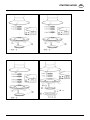
Hydraulic scheme EUROCAT 272 und 312 ............. 52
Hydraulic scheme EUROCAT 272 ED .................... 53
Combination of tractor and mounted implement ...... 54

- 5 -
9700_GB-Warnbilder_361
GB
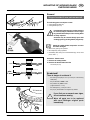
WARNING SIGNS
Stay clear of swinging area of implements
Close both side protective coverings before engaging
p.t.o..
Never reach into the crushing danger area as long as
parts may move.
CE sign
The CE sign, which is affixed by the manufacturer, indicates out ward ly that this machine
con forms to the engineering guideline regulations and the other relevant EU guidelines.
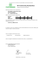
EU Declaration of Conformity (see supplement)
By signing the EU Declaration of Conformity, the ma nu fac tu r er declares that the machine being
brought into service complies with all relevant safety and health requirements.
Meaning of warning signs
Danger - flying objects; keep safe distance from the
machine as long as the engine is running.
Wait until all machine components have stopped
completely before touching them.
Stay clear of mower knife area as long as tractor engine
is running with PTO connected.
Shut off engine and remove key before performing
maintenance or repair work.
Recommendations
for work safety
All points referring
to satety in this
manual are
in di ca ted by this
sign.
bsb 447 410
495.167

- 6 -
1400-GB-ÜBERSICHT_3672
GB
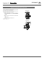
OVERVIEW
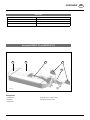
Overview EUROCAT 272 and EUROCAT 312
Designations:
(1) Headstock
(2) Lighting
(3) Cutter bar
(4) Swath former / hind protection
(5) Folding lateral protection
Variations
Description Description
EUROCAT 272 Working width: 2.70 m
EUROCAT 272 ED Working width: 2.70 m
EUROCAT 312 Working width: 3.05 m
1
5 4 3 2

- 7 -
1400-GB-ÜBERSICHT_3672
OVERVIEW GB
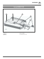
Overview EUROCAT 272 ED
Designations:
(1) Headstock
(2) Lighting
(3) Cutter bar
(4) Tine conditioner
(5) Folding lateral protection
1
5 4 3
2

- 8 -
1400-GB-SCHLEPPERVORAUSSETZUNG_3672
GB
TRACTOR REQUIREMENTS
Tractor
The following tractor requirements are necessary to operate the implement:
- Tractor power: EUROCAT 272 - from 44 kW /60 hp
EUROCAT 272 ED - from 51 kW / 70 hp
EUROCAT 312 - from 51 kW / 70 hp
- Hitching: EUROCAT 272 - lower link cat. II / III - width 2 / 3
EUROCAT 272 ED - lower link cat. III - width 2 / 3
EUROCAT 312 - lower link cat. III - width 2 / 3
- Connections: see table “Necessary hydraulic and power connections”
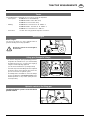
Ballast weights
Ballast weights
The front of the tractor is to have sufficient ballast to
guarantee braking and steering capabilities.
At least 20% of the tractor’s tare weight on
the front axle!
Lifting gear (three-point linkage)
- The tractor’s lifting unit (three-point linkage) must be
designed for the load that occurs. (See technical data)
- The lifting struts are to be set at the same length (4)
using the relevant adjusting equipment
(See the tractor manufacturer’s operating manual)
- Select the rear position if the lifting rods can be adjusted
in various positions on the lower link. This relieves the
pressure on the tractor’s hydraulic system.
- The limiting chains and stabilisers of the lower linkage
(5) are to be adjusted so that lateral movement of the
hitched implements is not possible. (Safety measure
for transportation)
Hydraulic control on the lifting gear
The lifting hydraulic system is to be switched to
position control:
20%
Kg
371-08-16
371-08-16

- 9 -
1400-GB-SCHLEPPERVORAUSSETZUNG_3672
TRACTOR REQUIREMENTS GB
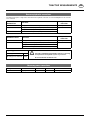
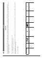
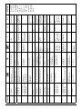
Necessary hydraulic connections
The implement requires a single-action and a dual-action hydraulic connection. See the following table for the elements
to be controlled:
EUROCAT 272
EUROCAT 312 Consumer Hydraulic
connection
Standard Lifting cylinder - between working and headland position Single-action
Standard Lifting cylinder - transport position (with pulled control line) Dual-action
Setting the relief (3-way cock at top)
Optional Hydraulic lower linkage rocker (3-way cock at bottom)
EUROCAT 272 ED Consumer Hydraulic
connection
Standard Lifting cylinder - between working and headland position Single-action
Standard Lifting cylinder - transport position (with pulled control line) Dual-action
Setting for relief (3-way cock at top)
Hydraulic lower linkage rocker (3-way cock at bottom)
Operating pressure Be advised!
Check the compatibility of the hydraulic oils before connecting
the implement to the hydraulic system of your tractor.
Do not mix mineral oils with bio oils!
Operating pressure minimum 170 bar
Operating pressure maximum 200 bar
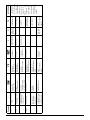
Necessary power connections
Design Consumer Pin Volt Power connection
Standard Lighting 7-pin 12 V DC According to DIN-ISO 1724

- 10 -
1401_GB-ANBAU_3672
GB
ATTACHING TO TRACTOR
Safety hints:
see Appendix-A1,
7.), 8a. - 8h.)
Caution
Implement is
designed for
operation only
with a tractor (not
with self-drive ma-
chines).
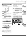
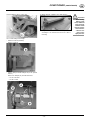
Attaching implement to tractor
1. Set lower link on tractor
- Fix the lower linkage so that the implement cannot
swivel out to the side and the headstock is positioned
to the middle.
2. Hitching implement to tractor
Be advised!
Risk of crushing! Before bringing the
tractor up to the implement, direct all
persons out of the danger area!
Be advised!
When hitching and unhitching the disc
mower, the tractor must be secured
against rolling before entering the danger
area between tractor and machine is
permitted!
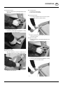
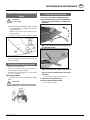
- Adjust the width of the lower link.
Push the lower link bolt into the holder at the lower link
and align to the required width (= hole) (1).
1
- Fix the lower link bolt in the holder with a screw. The
screw (2) must bite in the drilled hole selected (1) at
the lower link bolt.
2
Caution
If the screw is only fixed in the holder
and does not reach the drilled hole, then
this allows lateral movement of the bolt
and the mower can disconnect from the
coupling.
Be advised!
Use tractor’s
hydraulic lift only
when no one is
standing in the
danger area!
- The hydraulic lower linkage compensator is fitted in the
arrester hook of the left lower linkage by activating the
dual-action control unit.
- The mechanical lower link arm is adapted via the spindle.
- Connect upper link and secure.
Be advised!
Check cardan shaft length before initial
operation and adapt if necessary!
For details see Chapter "Cardan shaft"
in Attachment B of these Operating
Instructions cardan shaft.
- Connect hydraulic hoses depending on equipment.
- Connect the 7-pin plug for the lighting (optional) at the
tractor.
- Lay control line in tractor cabin.
- Fold up support stands and secure!
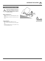
- Swivel safety flap
a. Set single-action hydraulic control system to floating
position!
b. Raise the tractor lifting device until the safety flaps
can be moved easily.
c. Safety flap (1) is to be moved to position B before
lifting to field transport position.
Pos. A
Pos. B
1
)

- 11 -
1401_GB-ANBAU_3672
GB
ATTACHING TO TRACTOR
Be advised!
During the adjust-
ment process,
no one is permit-
ted to be in the
machine area. The
mower units can
swing forward
slightly. Risk of
crushing!
Note:
Maintenance of
hydraulic relief:
Before lubricat-
ing the cylinder
suspension, the
relief pressure is
to be reduced to
0 to ensure even
lubrication.
Note:
A hydraulic upper link is recommended
(double-action control unit)
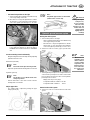
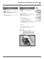
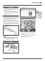
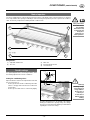
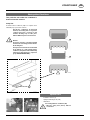
Hydraulic ground pressure system
Setting the relief system
1. Set lower link position to the right
- Set the mowing unit in floating position with the help
of the single acting control unit
- Move the hoist so long in the right direction, until the
arrow heads (1) of the lower link position indicator
on the relief cylinder point directly one to the other.
2. Set the lever of the cross valve (1) up to open the relief
system.
1
2
3. Set the hydraulic preload pressure using the dual-action
control unit. The preload pressure can be read off at the
pressure gauge (2). Reference values for the hydraulic
preload pressure ex works:
Display value at pressure gauge
for implement without conditioner: 110 bar
for implement with conditioner: 115 bar
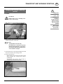
Control of the relief system
4. Set the lever of the cross valve down to block the relief
system.
1
- Set lower link position to the right
1. Set the mowing unit in floating position with the help
of the single acting control unit
2. Move the hoist so long in the right direction, until the
arrow heads (1) of the lower link position indicator
on the relief cylinder point directly one to the other.
1
This setting presupposes a distance from the ground
to the right lower link bolt of about 700 mm for
EUROCAT 312 and about 650 mm for EUROCAT
272
Set the mounting frame horizontally:
Bring mounting frame into horizontal position by adjusting
hydraulic lower link rocker
Mechanical (standard):
Note:
The mower is to be placed on the ground!
- Adjust the spindles until the hitching frame is horizontal.
Hydraulic (optional):
Note:
The mower is to be swivelled into field
transport position!
- Activate dual-action control unit at tractor until the
hitching frame is horizontal.
Adjust upper link
- The cutting height is adjusted by turning the upper
linkage spindle (16).

- 12 -
1401_GB-ANBAU_3672
GB
ATTACHING TO TRACTOR
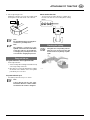
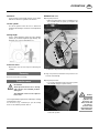
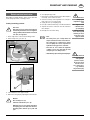
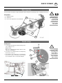
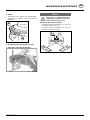
Check rotation direction
- The power take-off rotation direction is suitable when
the front view shows the outer mowing drums rotating
inward.
210-14-01
Checking the lighting
The lights and corresponding reflector
plates are to be check for function and
cleanness before any driving on public
roads.
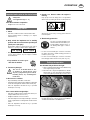
5. Check supporting pressure
by lifting the cutter bar on one side. The weight should
be 50 kg at the inside and outside of the cutter bar.
517-10-07
50 kg
Note:
Be careful that the degree of soiling does
not influence ground pressure.
Note:
The hydraulic connection for the
hydraulic relief on the mower is fitted with
a stop valve. This is to be opened prior
to changing the preload pressure and
re-closed after changing the pressure!
Carry out trial run
Set ground distance of the right lower link
- Set the right lower link.
1. Set the mowing unit in floating position with the help
of the single acting control unit
2. Move the hoist so long in the right direction, until the
arrow heads of the indicator on the relief cylinder
point directly one to the other.
Set power take-off r.p.m.
- Set suitable power take-off r.p.m. on tractor
Note:
A decal placed near the gear offers
information about the rotation number
for which the disc mower is designed.

- 13 -
1400_GB-TRANSPORT_3672
GB
TRANSPORT AND WORKING POSITION
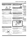
Safety hints:
See Attachment A1,
pt. 7.), 8c. - 8h.)
Changing from
working to
transport position
and vice versa is
only to be carried
out on even, firm
ground.
Never run the mow-
er in transport
position.
Changing from working position to field
transport position
Procedure:
Be advised!
Ensure that no one is standing in the
mower’s swivel range!
1) Raise the mower into field transport position using the
single-action control unit
Changing from field transport to
transport position
Procedure:
1) Turn drive off and wait for mower discs to come to a
standstill.
Be advised!
Ensure that no one is standing in the
mower’s swivel range!
2) Fold up side protection
for mechanical side protection:
1) Release locking device with screwdriver
2) Fold side protection up manually
With hydraulic side protection (optional), the side
protection folds up automatically on performance
of points 3 and 4.
3) Pull control line
4) At the same time swivel the mower into transport position
using the dual-action control unit.
Note:
(with hydraulic lower link arm)
If the dual-action control unit is activated
without having pulled the control line, then
the horizontal position of the headstock
changes!

- 14 -
1400_GB-TRANSPORT_3672
TRANSPORT AND WORKING POSITION GB
Safety hints:
See Attachment A1,
7.), 8c. - 8h.)
Changing from
working to
transport position
and vice versa is
only to be carried
out on even, firm
ground.
Never run the
mower in trans-
port position.
Changing from transport to working
position
Procedure:
Be advised!
Ensure that no one is standing in the
mower’s swivel range!
1) Pull control line to open the transport locking device.
2) At the same time swivel the mower into transport position
using the dual-action control unit.
Note:
(with hydraulic lower link arm)
If the dual-action control unit is activated
without having pulled the control line at
the same time, then the horizontal position
of the headstock changes!
3) Set the single-action control unit to floating position and
thus lower the mower into working position.
4) Fold off side protection
- with mechanical side protection: Push side protection
down manually. The locking device catches
automatically.
- with hydraulic side protection: Side protection is
automatically folded down and locked.

- 15 -
1500-GB EINSATZ 3672
GB
OPERATION
Important notes prior to the start of work
Safety hints:
See Supplement A, pt. 1. - 7.)
After the first hours of operation
• Retighten all screw connections.
Safety advice
1. Check
- Check the condition of knives and the knife holder.
- Check mowing drums for damage (see chapter
"Maintenance").
2. Only switch the implement on in working
position and do not exceed the specified pto
speed (max. 1,000 rpm)!
An illustration, which is located near the gear, advises
which p.t.o. speed your mower unit is equipped for.
• Only switch on the pto drive when all the safety devices
(covers, aprons, panels, etc.) are in proper condition
and folded down.
3. Pay attention to correct p.t.o.
direction of rotation!
TD8/95/6
4. Prevent any damage!
The area to be mowed must be free
of obstacles or foreign objects. Such
objects (e.g. large stones, pieces of wood,
boundary stones, etc.) can damage the
mower unit.
In the event of a collision
• Stop immediately and switch off the drive.
• Carefully check the implement for damage. In particular
check the mowing drums and their drive shafts (4a).
• Have the implement checked also by a specialist
workshop if necessary.
After contact with a foreign object
• Check the condition of knives and the knife holder (see
chapter "Maintenance and service").
• Retighten all blade screw connections.
• Check the implement carefully for damages. You must
check in particular the mowing drums and their drive
shafts.
• Have the implement checked also by a specialist
workshop if necessary.
5. Remain at a distance when the engine is
running.
- Keep people out of the danger zone - foreign bodies
which can be ejected by the mower could injure them.
bsb 447 410
Special care is necessary on stony ground and near
roads and paths.
6. Wear hearing protection
The noise level in the workplace can
deviate from the measured value (see
Technical Data) partly because of
the differing cabin types of various
tractors.
• If a noise level of 85 dB (A) is reached or exceeded,
the farmer must have suitable hearing protection in
readiness (UVV 1.1 §2).
• If a noise level of 90 dB (A) is reached or exceeded,
the hearing protection must be worn (UVV 1.1 § 16).
Settings for operation
Set the lower link position to the right
1. Set the mowing unit in floating position with the help
of the single acting control unit
2. Move the hoist so long in the right direction, until the
arrow heads (1) of the lower link position indicator
on the relief cylinder point directly one to the other.
1
This setting presupposes a distance from the ground to
the right lower link pin of about 700 mm for EUROCAT
312 and about 650 mm for EUROCAT 272
540 Upm 1000 Upm

- 16 -
1500-GB EINSATZ 3672
OPERATION GB
Headstock
- Set the headstock horizontally. Changes can be made
with the mechanical or hydraulic lower link arm.
Lift-out cylinder
- The lift-out cylinder control unit is to be switched to
floating position during use to achieve correct adjustment
to soil
Cutting height
- Set the cutting height by turning the upper linkage
spindle (16) or with the hydraulic upper linkage. The
maximum slope of the mowing drums is 5°.
Protective covers
- All protective covers are to be kept closed and in good
condition
Reversing
Raise the mower when reversing!
Protective covers
Be advised!
All the protective devices are to be kept
and locked in the intended positions
during use!
Any damaged covers are to be replaced
before use!
The side guard and front guard can be folded up for cleaning
and maintenance work.
You need a tool (e.g. screw driver) to open the locking
device of the foldable protection devices.
Caution:
Even with the
hydraulic side
protection, you
must ensure that
the side pro-
tection is in the
intended position
and locked there.
EUROCAT 272 / 312
Opening side protection:
1. Open the locking device using a screwdriver. Insert
the screwdriver into the eyelet (1) and pull in the
indicated direction.
1
2. Swivel the side protection up manually.
Closing side protection: Fold down side protection. The
bolt locks automatically.
Opening front protection:
1. Loosen the locking device in the form of the eyebolts
left and right using a tool (knife wrench).
2. Swivel up front protection manually. The protection
locks in this position.

- 17 -
1500-GB EINSATZ 3672
OPERATION GB
Closing front protection:
1. Release locking device by hand by pulling the knob
(2) inwards.
2. Fold down front protection.
3. Screw in the eyebolts again left and right thus securing
the protective cover in this position.
EUROCAT 272 ED
Opening side protection:
1. Open the locking device using a screwdriver. Insert
screwdriver in the eyelet (1) and press bolt away.
2. Swivel up side protection.
Close side protection
1. Fold down guard manually
2. The bolt locks automatically
Opening front protection:
1. Loosen the locking device in the form of the eyebolts
left and right using a tool (knife wrench).
2. Swivel up front protection manually. The protection
locks in this position.
Closing front protection:
1. Release locking device by hand by pulling the knob
(2) inwards.
2. Fold down front protection.
3. Screw in the eyebolts again left and right thus securing
the protective cover in this position.

- 18 -
1500-GB EINSATZ 3672
OPERATION GB
Starting up
- For mowing, slowly engage the clutch of the pto outside
the area to be mown (in field transport position) and
take the mowing rotors to full speed.
Smoothly increase the p.t.o. speed, in order to avoid
noises in the free-wheel conditioned by the system.
- The driving speed depends on the ground conditions
and the plants to be mown.
Function of the anti-collision safety
When harvesting around trees, fences, boundary stones
etc., despite cautious and slow driving, there might occur
collisions with the cutter bar. To avoid damages, the cutter
unit is equipped with an anti-collision safety.
In case of collision with an obstacle, the cutter bar swivels
around the deviation angle (circa 15°) backwards, when the
preload pressure of the anti-collision safety is exceeded.
To continue working, release the cutter unit from the
obstacle by driving backwards until the cutter bar swivels
back to working position.
Beware!
It is not the purpose of the anti-collision
safety to prevent damages on the
implement at full speed.
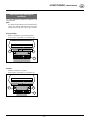
Setting the mechanical anti-collision
safety (1)
1
Set disc spring (see below) to the distance 110 mm to
ensure optimum function.
110 mm
Setting the hydraulic anti-collision safety
(Optional)
1
2
AB
1. Bring the lever (1) in accumulator charging position (A)
so as to be able to set the pressure in the hydraulic
accumulator.
2. Set the pressure at 120 bar by means of the double-
acting control unit (= setting ex-works). Can be read
on the manometer (2).
3. Bring the lever (1) in working position (B).
Be advised!
If you are not sure
whether the area
to be mown is
really free from
obstacles, then
drive slowly!

- 19 -
1400_GB-ABBAUEN_3672
GB
DISMOUNT AND PARKING
Attention!
• Always park
implement stead-
fast!
• Use support stand
- otherwise dan-
ger of tipping!
• Danger of injury
from crushing and
shearing sections
in the area of the
support stand!
Detach machine from tractor
Depending on parking situation, mower can be detached
in the transport position or working position.
Parking in working position:
Take note!
Only leave tractor to detach mower when it
is stationary and has been secured against
rolling, and when mower has been lowered
onto firm, even ground.
1. Reset single-action control unit to floating position.
2. Swivel safety lever (1) to (Pos. A)
Pos. A
Pos. B
1
3. Extend and secure support stand (2).
2
4. Lower implement onto support stands.
5. Relieve the safety flaps by adjusting the lower link arm.
Beware!
Check safety lever (1)!
It must be swivelled to (Pos. A)!
Otherwise there is the danger that when
uncoupling, the lower link of the mower’s
mounting frame swivels up in jerks and
jolts.
6. Uncoupling the upper link
7. Remove the control line from the tractor cabin and place
it rolled up on the mower unit shelf
8. Untension and cap off the hydraulic hoses and place
them on the hose rest of the mower
9. Unplug tractor’s 7-pole lighting plug
10. Uncouple cardan shaft and lay on cardan shaft holder.
11. Separate the tractor’s lower link from the machine’s
lower link pins
12. Carefully move the tractor away.
Note
The safety lever (1) is a safety fixture. Its
shape and function must not be altered.
The safety flap is constructed so that it
does not jump out of the lock position on
hydraulic moving up of the cutter bar.
• Therefore do not activate the hydraulic
cylinder to move the cutter bar up if the
safety flap is on locked position.
• Immediately replace damaged safety flaps.
Be advised!
Use the lower link
arm hydraulic
system to relieve
the arrester hook
and do not use
force. Using force
(e.g. hammer)
may lead to injury

- 20 -
1200_GB-SCHNITTHOEHE_344
STARTING WORK GB
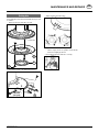
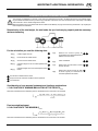
Operation
Set cutting height by turning upper link spindle (mower
drum incline, max. 50)
Central cutting height adjustment
The cutting height can be set anywhere from 35 to 65
mm by adjusting the centre disc.
1. Lift unit with loader (~5 cm).
2. The key (W) is put on the square or hexagon and turned
until the required cutting height is set.
Turn once = 1,5 mm
Cutting height adjustment
Safety points
- Turn engine off when
adjustment, service
and repair work is to
be done.
- Do not work under the
machine without safe
support.
- Retighten all screws after the first hours of operation.
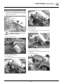
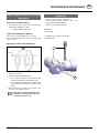
Distance plates
• The cutting height is set by inserting distance plates
(4mm, 6mm).
2 of which have already been inserted (4mm, 6mm) in
the factory.
Optional equipment: 8 distance plates (6mm)
Optional equipment: high-cut mowing plate (H1)
• Each mowing drum must have an equal number of
plates inserted.
Inserting distance plates
1. Remove both skide plates (S1, 1a).
2. Insert distance plates (6mm).
3. Refit both skid plates.
Replace worn or damaged spring lock washers with
new ones.
Similarly with worn screws and nuts.
Tighten all screws firmly!
4. Check after the first hour of operation
Check all screws for tightness.
TD 79/99/10
~ 5cm
TD 79/99/05
099-02-06
Page is loading ...
Page is loading ...
Page is loading ...
Page is loading ...
Page is loading ...
Page is loading ...
Page is loading ...
Page is loading ...
Page is loading ...
Page is loading ...
Page is loading ...
Page is loading ...
Page is loading ...
Page is loading ...
Page is loading ...
Page is loading ...
Page is loading ...
Page is loading ...
Page is loading ...
Page is loading ...
Page is loading ...
Page is loading ...
Page is loading ...
Page is loading ...
Page is loading ...
Page is loading ...
Page is loading ...
Page is loading ...
Page is loading ...
Page is loading ...
Page is loading ...
Page is loading ...
Page is loading ...
Page is loading ...
Page is loading ...
Page is loading ...
Page is loading ...
Page is loading ...
-
 1
1
-
 2
2
-
 3
3
-
 4
4
-
 5
5
-
 6
6
-
 7
7
-
 8
8
-
 9
9
-
 10
10
-
 11
11
-
 12
12
-
 13
13
-
 14
14
-
 15
15
-
 16
16
-
 17
17
-
 18
18
-
 19
19
-
 20
20
-
 21
21
-
 22
22
-
 23
23
-
 24
24
-
 25
25
-
 26
26
-
 27
27
-
 28
28
-
 29
29
-
 30
30
-
 31
31
-
 32
32
-
 33
33
-
 34
34
-
 35
35
-
 36
36
-
 37
37
-
 38
38
-
 39
39
-
 40
40
-
 41
41
-
 42
42
-
 43
43
-
 44
44
-
 45
45
-
 46
46
-
 47
47
-
 48
48
-
 49
49
-
 50
50
-
 51
51
-
 52
52
-
 53
53
-
 54
54
-
 55
55
-
 56
56
-
 57
57
-
 58
58


Pottinger EUROCAT 272 Operating instructions
- Category
- Kitchen & houseware accessories
- Type
- Operating instructions
- This manual is also suitable for
Ask a question and I''ll find the answer in the document
Finding information in a document is now easier with AI
Related papers
-
Pottinger NOVADISC 900 Operating instructions
-
-
-
-
-
-
-
-
-
Other documents
-
 Amazone Sliding frame VR 2 Operating instructions
-
GGM Gastro GSH300 Owner's manual
-
Krone BA EasyCut 280 CV-Q/CRI-Q, 320 CV-Q Operating instructions
-
Krone AM 203 S,243 S,283 S,323 S Operating instructions
-
Krone BA EasyCut F 360 CV/CR Operating instructions
-
-
