Page is loading ...

Specifications subject to change without notice.
TABLE of CONTENTS
PAGE
INTRODUCTION............................................................................ 1
MODEL / SERIAL NUMBER NOMENCLATURES .................... 2
WIRING ........................................................................................... 3
CONNECTION DIAGRAMS ......................................................... 4
WIRING DIAGRAM....................................................................... 5
REFRIGERATION CYCLE DIAGRAM........................................ 6
REFRIGERANT LINES .................................................................. 6
FAN AND MOTOR SPECIFICATIONS........................................ 7
SYSTEM EVACUATION AND CHARGING ............................... 8
INQUIRY MODE ............................................................................ 12
TROUBLESHOOTING ................................................................... 13
INDOOR UNIT DIAGNOSTIC GUIDES....................................... 14
DIAGNOSIS AND SOLUTION...................................................... 15
APPENDICIES ................................................................................ 37
DISASSEMBLY INSTRUCTIONS ................................................ 40
Installing, starting up, and servicing air conditioning equipment can
be hazardous due to system pressures, electrical components, and
equipment location (roofs, elevated structures, etc.). Only trained,
qualified installers and service mechanics should install, start-up, and
service this equipment. Untrained personnel can perform basic
maintenance functions such as coil cleaning. All other operations
should be performed by trained service personnel.
When working on the equipment, observe precautions in the literature
and on tags, stickers, and labels attached to the equipment. Follow all
safety codes. Wear safety glasses and work gloves. Keep a quenching
cloth and fire extinguisher nearby when brazing. Use care in handling,
rigging, and setting bulky equipment.
Read this manual thoroughly and follow all warnings or cautions
included in the literature and attached to the unit. Consult local
building codes and National Electrical Code (NEC) for special
requirements. Recognize safety information. This is the safety-alert
symbol . When you see this symbol on the unit and in instructions
or manuals, be alert to the potential for personal injury. Understand
these signal words: DANGER, WARNING, and CAUTION.
These words are used with the safety-alert symbol. DANGER
identifies the most serious hazards which will result in severe personal
injury or death. WARNING signifies hazards which could result in
personal injury or death. CAUTION is used to identify unsafe
practices which may result in minor personal injury or product and
property damage. NOTE is used to highlight suggestions which will
result in enhanced installation, reliability, or operation.
INTRODUCTION
This service manual provides the necessary information to service,
repair, and maintain the 40MAHB family of heat pumps. This manual
has an appendix (see “APPENDICIES” on page 37) with data
required to perform troubleshooting. Use the “TABLE of
CONTENTS”on page 1 to locate a desired topic.
ELECTRICAL SHOCK HAZARD
Failure to follow this warning could result in personal injury
or death.
Before installing, modifying, or servicing the system, the
main electrical disconnect switch must be in the OFF
position. There may be more than 1 disconnect switch. Lock
out and tag switch (es) with a suitable warning label.
WA R N I N G
EXPLOSION HAZARD
Failure to follow this warning could result
in death, serious personal injury, and/or
property damage. Never use air or gases
containing oxygen for leak testing or
operating refrigerant compressors.
Pressurized mixtures of air or gases
containing oxygen can lead to an explosion.
WA R N I N G
EQUIPMENT DAMAGE HAZARD
Failure to follow this caution may result in equipment damage
or improper operation.
Do not bury more than 36 in. (914 mm) of refrigerant pipe in
the ground. If any section of pipe is buried, there must be a 6
in. (152 mm) vertical rise to the valve connections on the
outdoor units. If more than the recommended length is buried,
refrigerant may migrate to the cooler buried section during
extended periods of a system shutdown. This causes
refrigerant slugging and could possibly damage the
compressor at start-up.
CAUTION
Service Manual
40MAHB
High Wall Ductless System
Sizes 06 to 36

40MAHB: Service Manual
Manufacturer reserves the right to change, at any time, specifications and designs without notice and without obligations.
2
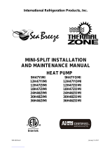
MODEL / SERIAL NUMBER NOMENCLATURES
Table 1 —Unit Sizes
SYSTEM TONS VOLTAGE INDOOR MODEL
1.00 115-1-60
40MAHBQ12XA1
0.50
208/230-1
40MAHBQ06XA3
0.75
40MAHBQ09XA3
1.00
40MAHBQ12XA3
1.50
40MAHBQ18XA3
2.00
40MAHBQ24XA3
2.50
40MAHBQ30XA3
3.00
40MAHBQ36XA3
INDOOR UNIT
40 MA H B Q 36
A
3
40 = INDOOR UNIT
MA = MODEL VOLTAGE
1=115-1-60
3=208/230-1-60
INDOOR UNIT FAN COIL UNIT TYPE
H = HIGH WALL
INDOOR FAN COIL TYPE
Q
= HEAT PUMP
NOMINAL CAPACITY
06 - 1/2 TON
09 - 3/4 TON
12 - 1 TON
18 - 1-1/2 TONS
24 - 2 TONS
30 - 2-1/2 TONS
36 - 3 TONS
MAJOR SERIES
VARIATIONS
A = STANDARD
X
MAXIMUM NUMBER OF FAN COILS
CONNECTED TO THE OUTDOOR UNIT
A = 1:1
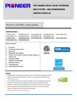
01 21 V 10001
Week of Manufacture
Year of Manufacture V = ALL MODELS
Sequential Serial Number
Use of the AHRI Certified
TM Mark indicates a
manufacturer’s
participation in the
program For verification
of certification for individual
products, go to
www.ahridirectory.org.

40MAHB: Service Manual
Manufacturer reserves the right to change, at any time, specifications and designs without notice and without obligations.
3
WIRING
All wires must be sized per NEC (National Electrical Code) or CEC
(Canadian Electrical Code) and local codes. Use the Electrical Data table
MCA (minimum circuit amps) and MOCP (maximum over current
protection) to correctly size the wires and the disconnect fuse or breakers
respectively.
Per the caution note, only stranded copper conductors with a 600 volt
insulation rating wire must be used.
Recommended Connection Method for Power and Communication
Wiring:
The main power is supplied to the outdoor unit. The field supplied 14/3
stranded wire with ground with a 600 volt insulation rating, power/
communication wiring from the outdoor unit to the indoor unit consists of
four (4) wires and provides the power for the indoor unit.
Two wires are line voltage AC power: connect L1 to terminal (1), N or L2
to (2), Communication wire to (3), green ground wire to ground terminal.
Refer to the “CONNECTION DIAGRAMS”on page 4 for 115 volt or
208/230 volt connection.
If installed in a high electromagnetic field area (EMF) and
communication issues exist, a 14/2 stranded shielded wire can be used to
replace (2) and (3) (polarity sensitive) between the outdoor unit and the
indoor unit landing the shield onto the ground in the outdoor unit only.
EQUIPMENT DAMAGE HAZARD
Failure to follow this caution may result in damage or
improper operation.
Wires should be sized based on NEC and local codes.
CAUTION
EQUIPMENT DAMAGE HAZARD
Failure to follow this caution may result in equipment damage
or improper operation.
Be sure to comply with local codes while running wire from
the indoor unit to the outdoor unit.
Every wire must be connected firmly. Loose wiring may
cause the terminal to overheat or result in unit malfunction. A
fire hazard may also exist. Ensure all wiring is tightly
connected.
No wire should touch the refrigerant tubing, compressor or
any moving parts.
Disconnecting means must be provided and shall be located
within sight and readily accessible from the air conditioner.
Connecting cable with conduit shall be routed through the
hole in the conduit panel.
CAUTION

40MAHB: Service Manual
Manufacturer reserves the right to change, at any time, specifications and designs without notice and without obligations.
4
CONNECTION DIAGRAMS
Fig. 1 — Connection Diagram - 12K (115V)
Fig. 2 — Connection Diagram - 6K - 18K (208/230-1-60)
Fig. 3 — Connection Diagram - 24K - 36K (208/230-1-60)
NOTES:
1. Do not use thermostat wire for any connection between indoor and outdoor units.
2. All connections between indoor and outdoor units must be as shown in figures 1 - 3. The connections are sensitive to polarity and will result in a fault
code.

40MAHB: Service Manual
Manufacturer reserves the right to change, at any time, specifications and designs without notice and without obligations.
5
WIRING DIAGRAM
Fig. 4 —Wiring Diagram (All Sizes) 115 and 208/230))

40MAHB: Service Manual
Manufacturer reserves the right to change, at any time, specifications and designs without notice and without obligations.
6
REFRIGERATION CYCLE DIAGRAM
Fig. 5 — Refrigeration Cycle Diagram
REFRIGERANT LINES
IMPORTANT: Both refrigerant lines must be insulated separately.
Refer to the outdoor unit’s installation instructions for other allowed piping lengths and refrigerant information.
T2 Evaporator
temp. sensor

40MAHB: Service Manual
Manufacturer reserves the right to change, at any time, specifications and designs without notice and without obligations.
7
FAN AND MOTOR SPECIFICATIONS
Table 2 — Fan and Motor Specifications
HIGH WALL
UNIT SIZE
12K 6K 9K 12K 18K 24K 30K 36K
(115 V) (208/230 V) (208/230 V) (208/230 V) (208/230 V) (208/230 V) (208/230 V) (208/230 V)
HIGH WALL FAN
Material
Acrylontrile
Styrene
+30%GF
Acrylontrile
Styrene
+30%GF
Acrylontrile
Styrene
+30%GF
Acrylontrile
Styrene
+30%GF
Acrylontrile
Styrene
+30%GF
Acrylontrile
Styrene
+30%GF
Acrylontrile
Styrene
+30%GF
Acrylontrile
Styrene
+30%GF
Type GL-98*638-IN GL-98*638-IN GL-98*638-IN GL-98*638-IN GL-98*758-IN GL-121*883-IN GL-121*883-IN GL-121*883-IN
Diameter In (mm) 3.86(98) 3.86(98) 3.86(98) 3.86(98) 3.86(98) 4.76(121) 4.76(121) 4.76(121)
Height In (mm) 25.12(638) 25.12(638) 25.12(638) 25.12(638) 29.84(758) 34.76(883) 34.76(883) 34.76(883)
HIGH WALL FAN MOTOR
Model ZKFP-20-8-113 ZKFP-20-8-6-21 ZKFP-20-8-6-21 ZKFP-20-8-6-21 ZKFP-30-8-3-10 ZKFP-58-8-1-6 ZKFP-58-8-1-6 ZKFP-58-8-1-6
Volts V 115 208/230 208/230 208/230 208/230 208/230 208/230 208/230
Phase 1 1111 1 1 1
FLA 0.2 0.25 0.25 0.25 0.13 0.5 0.5 0.5
MCA 0.25 0.31 0.31 0.31 0.16 0.63 0.63 0.63
Type DC
Insulation
class E
Safe class
IP20(Welling,
Dayang)/ IPX0
(Tongda)
IPX0 IPX0 IPX0 IPX4 IP20(Welling)/
IP40(Dayang)
IP20(Welling)/
IP40(Dayang)
IP20(Welling)/
IP40(Dayang)
Input W
65.8
(Welling,Tongda)/
68 (Dayang)
24.6 24.6 36 36 113.5(Welling)/
125(Dayang)
113.5(Welling)/
125(Dayang)
113.5(Welling)/
125(Dayang)
Output W 20 20 20 20 30 58 58 58
Range of
current Amps
0.467±10%
(Welling,Tongda)/
0.486±10%
(Dayang)
0.182±10% 0.182±10% 0.182±10% 0.11±10%
0.364±10%
(Welling)/0.4±10%
(Dayang)
0.364±10%
(Welling)/0.4±10%
(Dayang)
0.364±10%
(Welling)/0.4±10%
(Dayang)
Rated
current Amps
0.467
(Welling,Tongda)/
0.486 (Dayang)
0.182 0.182 0.182 0.11 0.364(Welling)/
0.4(Dayang)
0.364(Welling)/
0.4(Dayang)
0.364(Welling)/
0.4(Dayang)
Capacitor µF N/A
Rated HP HP 0.027 0.027 0.027 0.027 0.04 0.077 0.077 0.077
Speed rev/min 1200/910/720 1100/850/700 1100/850/700 1050/930/870 1240/1024/916 1000/850/700 1050/880/630 1050/880/630
Rated RPM rev/min 1200 1100 1100 1050 1240 1000 1050 1050
Max. input W 65.8 24.6 24.6 24.6 36 113.5 113.5 113.5

40MAHB: Service Manual
Manufacturer reserves the right to change, at any time, specifications and designs without notice and without obligations.
8
SYSTEM EVACUATION AND
CHARGING
Refrigerant tubes and indoor coil should be evacuated using the
recommended deep vacuum 500 microns method. The alternate triple
evacuation method may be used if the following procedure is followed.
Always break a vacuum with dry nitrogen.
NOTE: All units (except the 18,000 BTU model) have a Master
Suction and Liquid Line Service Valve.
System Vacuum and Charge
Using the Vacuum Pump
1. Completely tighten the flare nuts (A, B, C, D, E). Fully open all circuits
service valves. Connect the manifold gage charge hose to the charge
port of the low side Master service valve to evacuate all circuits at the
same time (see Fig. 6).
2. Connect the charge hose to the vacuum pump.
3. Fully open the low side of the manifold gage (see Fig. 7).
4. Start the vacuum pump.
5. Evacuate using the triple evacuation method.
6. After evacuation is complete, fully close the low side of the manifold
gage and stop the vacuum pump operation.
7. The factory charge, contained in the outdoor unit, is good for up to 25ft.
(8 m) of line length.
8. Disconnect the charge hose from the charge connection of the low side
service valve.
9. Securely tighten the service valves caps.
Fig. 6 —Service Valve
Fig. 7 —Manifold
Deep Vacuum Method
The deep vacuum method requires a vacuum pump capable of pulling a
vacuum of 500 microns and a vacuum gage capable of accurately
measuring this vacuum depth. The deep vacuum method is the most
effective way of assuring a system is free of air and liquid water (see Fig.
8).
Fig. 8 —Deep Vacuum Graph
Triple Evacuation Method
Refer to Fig. 9 and proceed as follows:
1. Pump the system down to 500 MICRONS of mercury and allow the
pump to continue operating for an additional 15 minutes.
2. Close the service valves and shut off the vacuum pump.
3. Connect a nitrogen cylinder and regulator to the system and open until
the system pressure is 2 psig.
4. Close the service valve and allow the system to stand for 10 minutes.
During this time, dry nitrogen can diffuse throughout the system
absorbing moisture.
5. Repeat this procedure as indicated in Fig. 9. Afterwards the system will
be free of any contaminants and water vapor.
Fig. 9 —Triple Evacuation Method
Final Tubing Check
IMPORTANT: Ensure the factory tubing on both the indoor and
outdoor unit has not shifted during shipment. Ensure the tubes are
not rubbing against each other or any sheet metal. Pay close attention
to the feeder tubes to ensure the wire ties on the feeder tubes are
secure and tight.
UNIT DAMAGE HAZARD
Failure to follow this caution may result in equipment damage
or improper operation.
Never use the system compressor as a vacuum pump.
CAUTION
Outdoor Unit Indoor Unit
Refrigerant
Service Valve
Low Side
High Side
A
B
C
D
Manifold Gage
500 microns
Low side valve High side valve
Charge hose
Charge hose
Vacuum pump
Low side valve
500
MINUTES
01234567
1000
1500
LEAK IN
SYSTEM
VACUUM TIGH
T
TOO WET
TIGHT
DRY SYSTEM
2000
MICRONS
2500
3000
3500
4000
4500
5000
CHECK FOR TIGHT, DRY SYSTEM
(IF IT HOLDS DEEP VACUUM)
EVACUATE
BREAK VACUUM WITH DRY NITROGEN
WAIT
EVACUATE
RELEASE CHARGE INTO SYSTEM
BREAK VACUUM WITH DRY NITROGEN
EVACUATE
WAIT

40MAHB: Service Manual
Manufacturer reserves the right to change, at any time, specifications and designs without notice and without obligations.
9
Main Protection
Fan speed is out of control
When the indoor fan speed is too low (300RPM) or too high (1500RPM)
for a certain time, the unit stops and the LED displays a failure.
Inverter module protection
The inverter module has a protection function for current, voltage and
temperature. If any of these protections engage, the corresponding code
displays on the indoor unit and the unit stops working.
Indoor fan delayed open function
When the unit starts up, the louver activates immediately and the indoor
fan opens 10s later. If the unit is running in the HEATING mode, the
indoor fan is controlled by the anti-cold wind function.
Zero crossing detection error protection
If the AC detects that the time interval is not correct for a continuous
240s, the unit stops and the LED displays the failure. The correct zero
crossing signal time interval should be between 6-13ms.
Sensor protection at open circuit and breaking disconnection
If only one temperature sensor malfunctions, the air conditioner continues
to work however the error code appears on the LED, in the event of any
emergency use. If more than one temperature sensor malfunctions, the air
conditioner stops working.
Operation Modes and Functions
FAN Mode
1. Outdoor fan and compressor stop
2. Temperature setting function is disabled and no setting temperature
appears.
3. Indoor fan can be set to high/med/low/auto
4. The louver operates the same as in the COOLING mode.
Fig. 10 —AUTO FAN Mode
COOLING Mode
Indoor Fan Running Rules:
In the COOLING mode, the indoor fan runs all the time and the speed
can be selected as HIGH, MEDIUM, LOW and AUTO. When the
setting temperature is reached, if the compressor stops running, the
indoor fan motor runs at the minimum or setting speed. The indoor fan is
controlled by the rules shown in Fig. 11.
Fig. 11 — Indoor Fan Running Rules
The AUTO fan is controlled by the rules shown in Fig. 12.
Fig. 12 — Indoor Fan Running Rules
Evaporator Temperature Protection
When the evaporator temperature is less than the setting value, the
compressor stops.
a
b
c
d
e
T1
°C
10.8
°F (6.0°C)
9°F (5.0°C)
7.2°F (4.0°C)
4.5°F (2.5°C)
1.8°F (1.0°C)
H
(H-L)*0.75+L
(H-L)*0.5+L
(H-L)*0.25+L
L
Setting fan
speed Actual fan speed
T1-Td (°F)
L
H
M

40MAHB: Service Manual
Manufacturer reserves the right to change, at any time, specifications and designs without notice and without obligations.
10
HEATING Mode
Indoor Fan Running Rules:
When the compressor is on, the indoor fan can be set to HIGH,
MEDIUM, LOW, AUTO, MUTE. When the indoor unit coil
temperature is low, the anti-cold air function starts and the indoor fan
motor runs at a low speed and the speed cannot be changed. When the
temperature is lower than the setting value, the indoor fan motor stops.
When the indoor temp reaches the setting temperature, the compressor
stops and the indoor fan motor runs at the minimum speed or setting
speed. The anti-cold air function is valid. The indoor fan is controlled as
shown in Fig. 13.
Fig. 13 —Indoor Fan Running Rules
AUTO Fan Action in HEATING Mode
Fig. 14 — AUTO Fan Action in HEATING Mode
DEFROSTING Mode
The air conditioner enters the DEFROSTING mode according to
the T3 temperature value and the T3 temperature change value
range plus the compressor running time. During the DEFROSTING
mode, the compressor continues to runs, the indoor and outdoor motors
stop, and the indoor unit defrost lamp illuminates and appears.
Evaporator Coil Temperature Protection
Fig. 15 — Evaporator Coil Temperature Protection
When the evaporator temperature is higher than the setting protection
value, the compressor stops.
AUTO Mode
This mode can be chosen with the remote controller and the setting
temperature can be changed between 62.6F(17C)~86F(30C). In the
AUTO mode, the air conditioner chooses the COOLING, HEATING or
FAN ONLY mode according to T (T =T1-Ts).
Fig. 16 — AUTO Mode
The indoor fan runs under AUTO fan in the relevant mode. The louver
operates the same as in relevant mode. If the air conditioner switches
between the HEATING and COOLING mode, the compressor stops for
a certain period of time and then chooses the mode according to T1-Ts. If
the setting temperature is modified, the air conditioner chooses the
running function again.
DRYING Mode
Indoor Fan Speed is Fixed
Indoor fan speed is fixed at BREEZE and can not be changed. The louver
angle is the same as in the COOLING mode.
Low Indoor Room Temperature Protection
In the DRYING mode, if the room temperature is lower than 50F
(10C), the compressor stops and will not resume until the room
temperature exceeds 53.6F (12C).
Setting fan
speed Actual fan speed
H=H
H+(H+=H+G)
M(M=M)
M+(M+=M+Z)
L(L=L)
L+(L+=L+D)
H- H-=H-G)
M-(M-=M-Z)
L-(L-=L-D)
T1-Td
L
H
M

40MAHB: Service Manual
Manufacturer reserves the right to change, at any time, specifications and designs without notice and without obligations.
11
Evaporator Anti-Freezing Protection
The evaporator anti-freezing protection condenser high temperature
protection and outdoor unit frequency limit are active and the same as that
in the COOLING mode.
Outdoor Fan
The outdoor fan operates the same as in the COOLING mode.
Forced Operation Function
When the air conditioner is off, press TOUCH to engage the Forced
AUTO mode. Press TOUCH again within 5 seconds to engage the
Forced COOLING mode. In the Forced AUTO, Forced COOLING
or any other operation mode, press TOUCH to turn off the air
conditioner.
Forced Operation Mode
In the Forced OPERATION mode, all the general protections and the
remote controller are available.
Operation Rules
Forced Cooling Mode
The compressor runs at the F2 frequency and the indoor fan runs in the
BREEZE mode. After running for 30 minutes. the air conditioner enters
the AUTO mode at the 75.2F(24C) setting temperature.
Forced Auto Mode:
The Forced AUTO mode is the same as the normal AUTO mode with a
75.2F(24C) setting temperature.
Forced DEFROSTING Mode:
1. Press and hold AUTO/COOL for 5s to enter the mode. The indoor fan
stops and the defrosting lamp illuminates. Use the remote
controller to exit this mode and turn off the air conditioner to stop the
normal DEFROSTING mode.
2. To exit the Forced DEFROSTING mode, press and hold AUTO/
COOL for 5s again.
AUTO-RESTART Function
The indoor unit is equipped with the AUTO-RESTART function,
which is carried out through an auto-restart module. In the event of a
sudden power failure, the module memorizes the setting conditions prior
to the power failure. The air conditioner resumes the previous operation
setting (not including the SWING function) automatically three (3)
minutes after the power returns.
If the memorization condition is the Forced COOLING mode, the air
conditioner runs in the COOLING mode for 30 minutes and turns to the
AUTO mode at the 75.2F(24C) setting temperature. If the air
conditioner is off before the power turns off and the air conditioner is
required to start up, the compressor delays start-up for 1 minute before
powering on. In other instances, the compressor waits three (3) minutes
before restarts.
Refrigerant Leakage Detection
With this new technology, the display area displays “EC” when the
outdoor unit detects a refrigerant leak. This function is only active in the
COOLING mode. The function can further prevent the compressor from
being damaged by a refrigerant leak or a compressor overload.
•Open Condition: When the compressor is active, the value of the coil
temperature of evaporator T2 experiences no to very little change.
Louver Position Memory Function
When starting the air conditioner again after a shut down, the louver
returns to the angle originally set by the user, however the precondition is
that the angle must be within the allowable range. If the louver exceeds
the allowable range, the air conditioner memorizes the maximum angle of
the louver. During operation, if the power fails or the end user shuts down
the air conditioner in the TURBO mode, the louver returns to the default
angle.
46F (8C) Heating
When the compressor is running, the indoor fan motor runs without the
ANTI−COLD air function. When the compressor is off, the indoor fan
motor is off.
Silence Operation
Press SILENCE on the remote controller to initiate the SILENCE
function. When SILENCE is activated, the compressor running
frequency remains lower than F2 and the indoor unit emits a faint breeze,
which reduces the noise to the lowest level and creates a quiet and
comfortable room for the user.
Inquiry Mode
Press and hold together the On/Off and Fan buttons for 8 seconds. The
remote control remains in Inquiry Mode for 1 minute if no button is
pressed. In the Inquiry Mode, the remote display cancels all icons except
AUTO, COOL, DRY, HEAT and battery strength. The digital display
defaults to “0” upon entering the Inquiry Mode. In Inquiry Mode, each
digital code (from 0 to 30) is accessed by pressing the UP or DOWN
arrow.

40MAHB: Service Manual
Manufacturer reserves the right to change, at any time, specifications and designs without notice and without obligations.
12
INQUIRY MODE
To enter the Inquiry Mode:
Press and hold together the On/Off and Fan buttons for 8 seconds. The remote control remains in Inquiry Mode for 1 minute if no button is
pressed. In the Inquiry Mode, the remote display cancels all icons except AUTO, COOL, DRY, HEAT and battery strength. The digital display
defaults to “0” upon entering the Inquiry Mode. In Inquiry Mode, each digital code (from 0 to 30) is accessed by pressing the UP or DOWN arrow.
Fig. 17 — Up and Down Arrow
The Inquiry information displays on the high wall indoor unit display in approximately 1 second of accessing the digital code. Press OK to send as
well.
Table 3 — Inquiry Codes and Symbols
To exit the Inquiry Mode:
Press and hold together the On/Off and Fan buttons for 2 seconds
CODE INQUIRY SYMBOL DESCRIPTION
Code 0 None
Code 1 T1 Indoor ambient
Code 2 T2 Indoor pipe
Code 3 T3 Outdoor pipe
Code 4 T4 Outdoor air
Code 5 TP (T5) Compressor discharge
Code 6 FT Compressor target frequency
Code 7 Fr Compressor run frequency
Code 8 dL Unit amperage
Code 9 Uo Unit voltage
Code 10 Sn Capacity test (special usage)
Code 11 ---- N/A
Code 12 Pr Indoor fan speed
Code 13 Lr Electronic Expansion Valve (EEV) opening
Code 14 ir Indoor fan speed
Code 15 HU Humidity
Code 16 TT Setpoint compensation temperature
Code 17 dT Dust concentration (not used)
Code 18 WIFI Wi-Fi signal strength
Code 19 ---- N/A
Code 20 oT Indoor fan target frequency
Code 21 ---- N/A
Code 22 ---- N/A
Code 23 ---- N/A
Code 24 ---- N/A
Code 25 ---- N/A
Code 26 ---- N/A
Code 27 ---- N/A
Code 28 ---- N/A
Code 29 ---- N/A
Code 30 ---- N/A

40MAHB: Service Manual
Manufacturer reserves the right to change, at any time, specifications and designs without notice and without obligations.
13
TROUBLESHOOTING
Safety
Electricity power is kept in the capacitors even if the power supply is shut off.
NOTE: Remember to discharge the electricity power in capacitor.
Fig. 18 —Electrolytic Capacitors
For other models, please connect discharge resistance (approximately 100 40W) or a soldering iron (plug) between the +, - terminals of the
electrolytic capacitor on the contrary side of the outdoor PCB.
Fig. 19 —Discharge Position
NOTE: Fig. 19 is for reference only. The plug on your unit may differ.
Electrolytic Capacitors
(HIGH VOLTAGE! CAUTION!)

40MAHB: Service Manual
Manufacturer reserves the right to change, at any time, specifications and designs without notice and without obligations.
14
INDOOR UNIT DIAGNOSTIC GUIDES
For ease of service, the systems are equipped with diagnostic code display LEDs on the indoor unit. There may be a few error codes displayed in the
indoor unit that might relate to the outdoor unit's problems. If possible, always check the diagnostic codes displayed on the indoor unit first.
Table 4 — Indoor Unit Diagnostic Guides
☆ = Flashing, X = Off
Table 5 — Indoor Unit Diagnostic Guides
O (on − light) X (off − light) ☆(flash)
GREEN LED RED LED FAILURE MODE
On X Standby, normal
X On Operation, normal
On On High/Low voltage protection on compressor terminal
On ☆EEPROM error
X☆The compressor speed is out of control
☆On Zero-crossing signal detection error; lack of phase; synchronization error
☆X IGBT or Module protection
☆☆Communication error
OPERATION LAMP (TIMES) TIMER LAMP DISPLAY ERROR INFORMATION
☆1OFFEH 00/EH 0A Indoor unit EEPROM parameter error
☆2OFFEL 01 Indoor/outdoor unit communication error
☆3OFFEH 02 Zero-crossing signal detection error
☆4OFFEH 03 Indoor fan operating outside of the normal range
☆5OFFEC 51 Outdoor unit EEPROM parameter error
☆5OFFEC 52 T3 is in open circuit or has short circuited
☆5OFFEC 53 T4 is in open circuit or has short circuited
☆5OFFEC 54 TP is in open circuit or has short circuited
☆5OFFEC 56 T2B is in open circuit or has short circuited
☆6OFFEH 60 T1 is in open circuit or has short circuited
☆6OFFEH 61 T2 is in open circuit or has short circuited
☆12 OFF EC 07 Outdoor fan operating outside of the normal range
☆9OFFEH 0b Indoor PCB/Display board communication error
☆8OFFEL 0C Refrigerant leakage detection
☆7 FLASH PC 00 IPM malfunction or IGBT OSCP
☆2 FLASH PC 01 Over voltage or over low voltage protection
☆3 FLASH PC 02 Compressor or IPM high temp/pressure protection
☆5 FLASH PC 04 Inverter compressor drive error
☆1 FLASH PC 08 Current overload protection
☆6 FLASH PC 40 Comm. error between outdoor chip and compressor chip
☆7 FLASH PC 03 Low pressure protection
☆1ON-- Indoor units mode conflict
☆9OFFEH b1 Indoor board and Multi-function communication error
☆11 OFF FH 0d Ionizer malfunction

40MAHB: Service Manual
Manufacturer reserves the right to change, at any time, specifications and designs without notice and without obligations.
15
DIAGNOSIS AND SOLUTION
Outdoor Unit Error Display
After the power is on, LED1 (blue color) flashes slowly (once per second) when the unit is in standby. The LED flashes quickly (twice per second) if
the unit has an issue.
Table 6 — Diagnostic Table Sizes 9K-18K
O (light) X (off) (2.5 Hz flash)
Table 7 — Diagnostic Table Sizes 24K- 36K
NO. PROBLEMS LED3 (GREEN) LED2 (RED) IU DISPLAY SOLUTION
1 IPM malfunction or IGBT over - strong current protection XP0 Page 28
2 Over voltage or too low voltage protection O O P1 Page 31
3 EEPROM parameter error O E5 Page 16
4 Inverter compressor drive error X P4 Page 35
5 Inverter compressor drive error OP4 Page 35
6 Inverter compressor drive error P4 Page 35
NO. PROBLEMS LED2 (GREEN) LED3 (RED) IU DISPLAY SOLUTION
1 IPM malfunction or IGBT over - strong current protection XP0 Page 28
2 Over voltage or too low voltage protection O O P1 Page 31
3 EEPROM parameter error O E5 Page 16
4 Inverter compressor drive error X P4 Page 35
5 Inverter compressor drive error OP4 Page 35
6 Inverter compressor drive error P4 Page 35

40MAHB: Service Manual
Manufacturer reserves the right to change, at any time, specifications and designs without notice and without obligations.
16
DIAGNOSIS AND SOLUTION (CONT)
Outdoor EEPROM Parameter Error or Compressor Driven Chip EEPROM Parameter Error (EC51)
Description: Outdoor PCB main chip does not receive feedback from the EEPROM chip or the compressor driven chip.
Recommended parts to repair:
• Outdoor PCB
Troubleshooting
Shut o the power. Wait two
minutes then turn the unit on.
Does the error code
still appear?
YES
Replace the outdoor main PCB.
The unit is operating normally.NO

40MAHB: Service Manual
Manufacturer reserves the right to change, at any time, specifications and designs without notice and without obligations.
17
DIAGNOSIS AND SOLUTION (CONT)
Indoor and Outdoor Unit Communication Error (EL01)
Description: The indoor unit cannot communicate with the outdoor unit
Recommended parts to repair:
• Indoor PCB
• Outdoor PCB
• Short-circuited component
Troubleshooting
For certain models, outdoor PCB could not be removed separately. In this case, the outdoor electric control box should be replaced as a whole.
Does the error code
disappear?
Power o, then restart the unit after 2
minutes.
Measure the DC voltage between N/L2
and S (red pin to N/L2, black pin to S).
The value is xed and close to 0.
The value is alternative
from negative to positive.
The value is always positive
Check the wiring connection
between the indoor and
outdoor units.
Are they OK?
between the indoor and outdoor
Check the wiring connection
from outdoor terminal to
outdoor PCB and wiring
between PCBs if there is
more than 1 PCB
Check the wiring connection
from indoor terminal to indoor
PCB. Are they OK?
Turn on the unit, check if W
and 1(L) are connected.
Check that the power
LED is on.
No
Yes
Yes
Unplug all the high voltage
components connected to the
main PCB ( 4-way valve, heater,
AC fan) one by one to check
their resistance. Has any
component short circuit?
Unplug the electronic expansion
valve. Check if the power LED is on.
No
No
Check the AC voltage of L, N
output to IPM board. Is it the
same as the power input?
Check the DC 5V, 12V
from IPM board to main
PCB. Are they OK?
Unplug all the high voltage
components connected to main
PCB (4 way valve, heater, AC fan)
one by one to check their resistance.
Has any component short circuited?
Yes
No
Unplug electronic expansion valve.
Check if the DC 5V, 12V to the main
PCB are ok.
Replace short-circuited
component and main
PCB. PCB
Replace the electronic
expanson valve coil.
Replace the
outdoor PCB.
Replace the short
-circuited component
and the outdoor PCB.
PCB
Yes
Yes
Yes
Yes
Replace the
main PCB.
No
Yes
No
Replace the IPM board.
No
Replace the
indoor PCB.
No
Solved
Correct the connection or
change wires.
No
Yes
Yes
For units with main PCB and IPM board both.
For units with only one PCB
For units
with W wire
For units without W wire
No

40MAHB: Service Manual
Manufacturer reserves the right to change, at any time, specifications and designs without notice and without obligations.
18
DIAGNOSIS AND SOLUTION (CONT)
Remarks:
• Use a multimeter to test the DC voltage between the 2 port (or S or L2 port) and 3 port (or N or S port) of the outdoor unit.
• The red pin of multimeter connects with 2 port (or S or L2 port) while the black pin is for 3 port (or N or S port) the unit is running normal, the
voltage is moving alternately as positive values and negative values.
• If the outdoor unit malfunctions, the voltage remains in a narrow positive value.
• If the indoor unit malfunctions, the voltage maintains a fixed value.
• Use a multimeter to test the reactor’s resistance which does not connect with capacitor.
• The normal value should be around zero ohm. Otherwise, the reactor has malfunctioned. Check the reactor and make sure it is not shorted to the
ground.
S and N
or
L2 and S
or
2 and 3

40MAHB: Service Manual
Manufacturer reserves the right to change, at any time, specifications and designs without notice and without obligations.
19
DIAGNOSIS AND SOLUTION (CONT)
Zero Crossing Detection Error Diagnosis and Solution (EH02)
Description: When the PCB does not receive a zero crossing signal feedback for 4 minutes or the zero crossing signal time interval is abnormal.
Recommended parts to repair:
• Connection wires
• Indoor main PCB
Troubleshooting
Note: Zero crossing detection error is only valid for the unit with an AC fan motor. For other models, this error does not apply.
Check the connections and
power supply.
Correct the connections. Turn on the
unit when the power supply is on.
NO
Indoor main PCB is defective.
Replace the indoor main PCB.
YES
Is it normal?

40MAHB: Service Manual
Manufacturer reserves the right to change, at any time, specifications and designs without notice and without obligations.
20
DIAGNOSIS AND SOLUTION (CONT)
The indoor fan speed is operating outside of the normal range (EH03)
Description: When the indoor fan speed remains too slow or too fast for an extended period of time, the LED displays a failure code and the
unit turns off.
Recommended parts to repair:
• Connection wires
• Indoor main PCB
• Fan assembly
• Indoor main PCB
Troubleshooting
YES
Turn the power o. Wait 2 minutes, then restart.
Is it within normal parameters?
Replace the fan motor.
Does a problem remain? The unit is operating normally. NO
Shut o the power supply.
Rotate the fan by hand.
YES
Does it turn easily? Find the cause of the problem and resolve.
NO
Check the fan motor wiring.
YES
Is it improperly wired? Ensure the connections are good.
Measure the voltage for
the fan motor from the PCB.
YES
Replace the indoor main PCB.NO
/