Simplicity 2691519 User manual

Category
Lawnmowers
Type
User manual
© Briggs & Stratton
Milwaukee, WI, USA. All Rights Reserved. 80079525
Revision C
Not for
Reproduction
2
Manual Contents:
General Information..............................................................2
California Spark Arrester Warning......................................2
California Proposition 65..................................................... 2
Operator Safety..................................................................... 2
Features and Controls..........................................................5
Operation............................................................................... 7
Maintenance.........................................................................14
Troubleshooting..................................................................21
Specifications......................................................................22
General Information
For additional information, refer to theCustomer Contact
Guideincluded with the unit.
The illustrations in this document are representative.
Your unit might look different from the images
shown.LEFTandRIGHTare referenced from the operator's
position.
The use of Important and Note in the text shows clarifications,
exceptions, or alternatives to the procedures.
All language translations of this document derive from the
initial English source file.
Recycle all packaging, used oil, and batteries according to
applicable government regulations.
California Spark Arrester
Warning
WARNING
It is a violation of California Public Resource Code, Section
4442, to use or operate the engine on any forest-covered,
brush-covered, or grass-covered land unless the exhaust
system is equipped with a spark arrester, as defined
in Section 4442, maintained in effective working order.
Other states or federal jurisdictions may have similar laws.
Contact the original equipment manufacturer, retailer, or
dealer to obtain a spark arrester designed for the exhaust
system installed on this engine.
WARNING
Battery posts, terminals, and related accessories
contain lead and lead compounds, chemicals known to
the State of California to cause cancer and birth defects
or other reproductive harm. Wash hands after handling.
California Proposition 65
This product can expose you to chemicals including
gasoline engine exhaust, which is known to the State of
California to cause cancer, and carbon monoxide, which
is known to the State of California to cause birth defects
or other reproductive harm. For more information go to
www.P65Warnings.ca.gov.
Operator Safety
Save these instructions for future reference.This manual
contains safety information to make you aware of the hazards
and risks associated with the product and how to avoid them.
It also contains important instructions that must be obeyed
during the initial set-up, operation, and maintenance of the
product.
This product is designed and intended for cutting well
maintained grass and is not intended for other purposes.
It is important that you read and understand these instructions
before you attempt to start or operate this equipment.
Make sure that you are fully familiar with the controls and the
correct use of the product.
Know how to stop the unit and disengage controls quickly.
Slope Identification Guide
1
How to measure the slope of a lawn surface with a
smartphone or an angle finder tool:
Not for
Reproduction
3
WARNING
Do not operate on slopes greater than10degrees.
1. Use a straight edge at least two (2) feet long (A,
Figure1). A 2x4 or a straight piece of metal works well.
2. Angle finder tools.
a. Use your smartphone:Many smartphones (B,
Figure1) have an inclinometer (angle finder) located
under the compass application (app). Or, search an
app store for an Inclinometer app.
b. Use angle finder tools:Angle finder tools (C and
D, Figure1) are available at local hardware stores
or online (also called inclinometer, protractor, angle
meter, or angle gauge). Dial type (C) or digital type
(D) work, others may not.Read and obey the user
instructions supplied with the angle finder tool.
3. Put the two (2) feet long straight edge along the steepest
part of the lawn slope. Put the board up and down the
slope.
4. Lay the smartphone or angle finder tool on the straight
edge and read the angle in degrees. This is the slope of
your lawn.
Note:A paper gauge slope identification guide is included
in your product literature packet and is also available to
download from the manufacturer's website.
Safety Symbols and Meanings
Symbol Meaning
Safety information about hazards that can result in personal
injury.
Read and understand the Operator's Manual before you
operate or service the unit.
Remove the key and read the Operator's Manual before
you service the unit.
Stop
Fire hazard
Symbol Meaning
Explosion hazard
Shock hazard
Toxic fume hazard
Moving parts
Wear eye protection.
Hazardous chemical
Hot surface hazard
Amputation hazard
Thrown objects hazard
Keep a safe distance
Keep children away
Not for
Reproduction
4
Symbol Meaning
Roll-over hazard
Amputation hazard
Safety Alert Symbol and Signal Words
The safety alert symbol identifies safety information
about hazards that can result in personal injury. A signal word
(DANGER,WARNING, orCAUTION) is used with the alert
symbol to indicate the likelihood and the potential severity of
injury. In addition, a hazard symbol may be used to represent
the type of hazard.
DANGERindicates a hazard which, if not
avoided,willresult in death or serious injury.
WARNINGindicates a hazard which, if not
avoided,couldresult in death or serious injury.
CAUTIONindicates a hazard which, if not
avoided,couldresult in minor or moderate injury.
NOTICEindicates information considered important but not
hazard-related.
Safety Decals
Before operating your machine, read and understand the
safety decals. Compare Figure 2 with the table following.
The cautions and warnings are for your safety. To avoid a
personal injury or damage to the machine, understand and
follow all the safety decals.
Important:If any safety decals become worn or damaged,
and cannot be read, order replacement decals from your local
dealer.
2
ADecal, Main Safety
Part No. 5106564
BDecal, Danger, Thrown
Objects
Part No. 7101665
Not for
Reproduction
5
Battery Safety Decal
Warning: Fire Hazard - Keep children,
open flames and sparks away from the
battery, which could ignite explosive gases.
Warning: Sulfuric acid can cause
blindness or severe burns -Always
wear safety goggles or a face shield when
working on or near a battery.
Warning: Batteries produce explosive
gases - Read and understand the
Operator’s Manual before using this
machine.
Important: Do not discard a battery in the
trash - Contact local authorities for disposal
and/or recycling of batteries.
Flush eyes immediately with water. Get
medical help fast.
Safety Messages
WARNING
Read, understand, and obey all the instructions and
warnings in the Operator's Manual and on the machine,
engine, and attachments before you operate this machine.
Failure to obey the safety instructions in this manual and on
the equipment could result in death or serious injury.
Only let operators who are responsible, trained and
familiar with the instructions and physically capable to
operate the machine.
Do not operate the machine while under the influence of
alcohol or drugs.
Wear safety glasses and closed toe footwear.
Do not put hands or feet near rotating parts or under
the machine. Keep clear of the discharge opening at all
times.
Keep the machine in good working order. Replace worn
or damaged parts.
Be careful when youservice the blades. Wrap the
blades or wear gloves. Replace damaged blades. Do
not repair or alterthe blades.
Use full width ramps when you load and unload a
machine for transport.
See attachment or accessory for proper wheel weights
or counterweights.
To help prevent fires, keep machine free of grass,
leaves, or other unwanted material. Clean remaining oil
or fuel spillage. Remove fuel soaked debris and let the
machine to cool before storage.
WARNING
Running engine gives off carbon monoxide, an odorless,
colorless, poison gas. Breathing carbon monoxide can
cause headaches, fatigue, dizziness, vomiting, confusion,
seizures, nausea, fainting or death.
Operate equipment ONLY outdoors.
Keep exhaust gas from entering a confined area
through windows, doors, ventilation intakes, or other
openings.
Features and Controls
Compare the features and controls in Figure3with the table
following.
Not for
Reproduction
6
3
Ref. Description / Function Icon(s) Definition /
Operation
A Deck Lift Pedal, Cutting Height
Adjustment Pin and Deck Lift Lock
Lever - adjusts cutting height
SeeCutting Height
Adjustment
B Right Ground Speed Lever -
controls speed and direction of right
drive wheel; also engages parking
brake
Forward ground
speed increase - push
lever forward
Neutral - release
lever
Engine start - move
lever out
Reverse ground
speed increase - pull
lever back
Parking brake engage
- move lever out
Engine off
Engine on (run)
C Ignition Switch - starts engine
Engine start
Choke on (closed) -
Briggs engines only
Engine speed fast
D Engine Speed Control - controls
engine speed
Engine speed slow
E PTO Switch - engages and
disengages mower blade clutch
PTO engage - pull up
on switch
F Hour Meter Indicates total hours
of engine operation
G Transmission Release Levers -
release transmissions so unit can
roll freely
SeePushing the
Unit by Hand
H Fuel Tank Cap Turn cap
counterclockwise to
remove
I Operator's Seat Adjust SeeSeat
Adjustments
Not for
Reproduction
7
J Left Ground Speed Lever - controls
speed and direction of left drive
wheel
Forward ground
speed increase - push
lever forward
Neutral - release
lever
Engine start - move
lever out
Reverse ground
speed increase - pull
lever back
Operation
Operating Area
1. Know the area where you plan to operate the mower.
2. Make sure that the area is free of unwanted material that
could be picked up by the blades and thrown.
DANGER
This machine can throw objects that could cause injury to
bystanders or damage to buildings.
Do not operate the machine without the entire grass
catcher, discharge chute, or other safety devices in
place and operating correctly. Check frequently for
signs of wear or deterioration and replace as needed.
Clear the operating area of any objects which could be
thrown by or cause interference to the operation of the
machine.
3. Move the rider mower outside, before you start the
engine.
WARNING
Engines give off carbon monoxide, an odorless, colorless,
poison gas. Breathing carbon monoxide can cause nausea,
fainting, or death.
4. Note all slopes and drop-offs.
DANGER
Operating on slopes, or near water, or drop-offs can result
in loss of control and roll-over.
Avoid turning down slopes; if possible turn up slopes.
Decrease speed and be careful on slopes.
Do not operate on slopes over 10 degrees, which is a
3.5 foot rise over a 20 foot length.
Do not operate down slopes toward or near water,
retaining walls, or drop-offs.
Give yourself a minimum of two mower widths of
clearance around water, retaining walls, or drop-offs.
Do not mow wet grass.
Do not operate machine under any condition where
traction, steering, or stability is in question. Tires could
slide even if the wheels are stopped.
Do not start and stop on slopes.
Do not make sudden changes in speed or direction.
Make turns slowly and gradually.
Be careful while operating the machine with a grass
catcher or other attachment(s). They can affect the
stability of the machine.
Obey the manufacturer's instructions for weight limits
for towed equipment and towing on slopes. SeeTowed
Equipment.
5. Make sure that the operating area is clear of bystanders,
especially children.
DANGER
This rider mower is capable of amputating hands and feet.
Stop the mower when children or others are near.
Keep children out of the operating area and under adult
supervision.
Do not carry passengers, especially children, even
with the blade(s) shut off. Children can fall off and be
seriously injured or interfere with the safe machine
operation. Children who have been given rides in
the past can suddenly appear in the mowing area for
another ride and be run over or backed over by the
machine.
Use care when approaching blind corners, shrubs,
trees, or other objects that block vision.
Safety Interlock Systems Checks
DANGER
DO NOT operate machine if any safety interlock or safety
device is not in place and functioning properly. Contact
your dealer immediately for assistance. DO NOT attempt to
defeat, modify or remove any safety device.
TEST 1 - Engine must not crank if:
PTO switch is engaged, OR,
Not for
Reproduction
8
Ground speed levers are not locked in their START /
PARK positions.
TEST 2 - Engine should crank if:
PTO switch is NOT engaged, AND,
Ground speed levers are locked in their START / PARK
positions.
TEST 3 - Engine must shut off if:
Operator rises off seat with PTO engaged, OR
Operator rises off seat with ground speed levers not
locked in their START / PARK positions.
TEST 4 - Check mower blade stopping time
The mower blades and mower drive belt should come to
a complete stop within five seconds after the electric PTO
switch is turned off. If mower drive belt does not stop within
five seconds, see your dealer.
Note:Once the engine has stopped, the PTO switch must
be turned off and the ground speed levers must be locked in
their START/PARK positions in order to start the engine.
Oil Recommendations
Oil Capacity:See theSpecificationssection.
We recommend the use of Briggs & Stratton®Warranty
Certified oils for best performance. Other high-quality
detergent oils are acceptable if classified for service SF, SG,
SH, SJ or higher. Do not use special additives.
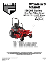
Outdoor temperatures determine the proper oil viscosity for
the engine. Use the chart to select the best viscosity for the
outdoor temperature range expected.
A SAE 30 -Below 40 °F (4 °C) the use of SAE 30 will result in hard
starting.
B 10W-30 -Above 80 °F (27 °C) the use of 10W-30 may cause
increased oil consumption. Check oil level more frequently.
C Synthetic 5W-30
D 5W-30
Check Oil Level
See Figure: 4
Before adding or checking the oil
Make sure the engine is level.
Clean the oil fill area of any debris.
1. Remove the dipstick (A, Figure 4) and wipe with a clean
cloth.
4
2. Install and tighten the dipstick (A, Figure 4).
3. Remove the dipstick and check the oil level. Correct oil
level is at the top of the full indicator (B, Figure 4) on the
dipstick.
4. If oil level is low, slowly add oil into the engine oil fill
(C, Figure 4). Do not overfill. After adding oil, wait one
minute and then recheck the oil level.
Note:Do not add oil at the quick oil drain , if equipped. For
location, see Features and Controls.
5. Reinstall and tighten the dipstick (A, Figure 4).
Oil Pressure
If the oil pressure is too low, a pressure switch (if equipped)
will either stop the engine or activate a warning device on the
equipment. If this occurs, stop the engine and check the oil
level with the dipstick.
If the oil level is below the ADD mark, add oil until it touches
the FULL mark. Start the engine and check for the correct oil
pressure before you continue to operate the machine.
If the oil level is between the ADD and FULL marks,DO NOT
start the engine. Contact an authorized service dealer to
correct the oil pressure problem.
Fuel Recommendations
Fuel must meet these requirements:
Clean, fresh, unleaded gasoline.
A minimum of 87 octane / 87 AKI (91 RON). For high
altitude use, see below.
Gasoline with up to 10% ethanol (gasohol) is acceptable.
NOTICE Do not use unapproved gasolines, such as E15
and E85. Do not mix oil in gasoline or modify the engine to
run on alternate fuels. Use of unapproved fuels will cause
damage to engine components, which will not be covered
under warranty.
To protect the fuel system from gum formation, mix a fuel
stabilizer into the fuel. See the appropriate Operator's
Not for
Reproduction
9
Manual for recommendations. All fuel is not the same.
If starting or performance problems occur, change fuel
providers or change brands. This engine is certified to
operate on gasoline. The emissions control system for this
engine is EM (Engine Modifications).
High Altitude
At altitudes over 5,000 feet (1524 meters), a minimum 85
octane/85 AKI (89 RON) gasoline is acceptable.
For carbureted engines, high altitude adjustment is
required to maintain performance. Operation without this
adjustment will cause decreased performance, increased
fuel consumption, and increased emissions. Contact
a Briggs & Stratton Authorized Service Dealer for high
altitude adjustment information. Operation of the engine at
altitudes below 2,500 feet (762 meters) with the high altitude
adjustment is not recommended.
For Electronic Fuel Injection (EFI) engines, no high altitude
adjustment is necessary.
Adding Fuel
WARNING
Fuel and its vapors are extremely flammable and
explosive.
Fire or explosion can cause severe burns or death.
When Adding Fuel
Turn engine off and let engine cool at least 3 minutes
before removing the fuel cap.
Extinguish all cigarettes, cigars, pipes, and other
sources of ignition.
Fill fuel tank outdoors or in a well-ventilated area.
Do not overfill fuel tank. To allow for expansion of the
fuel, do not fill above the bottom of the fuel tank neck.
Keep fuel away from sparks, open flames, pilot lights,
heat, and other ignition sources.
Check fuel lines, tank, cap, and fittings frequently for
cracks or leaks. Replace if necessary.
If fuel spills, wait until it evaporates before starting
engine.
1. Clean the fuel cap area of dirt and debris. Remove the
fuel cap (A, Figure5).
2. Fill the fuel tank with fuel. To allow for expansion of the
fuel, do not fill above the bottom of the fuel tank neck (B).
3. Reinstall the fuel cap.
5
Starting the Engine
WARNING
If you do not understand how a specific control
functions, or have not yet thoroughly read the Features
& Controls section, do so now.
Do NOT attempt to operate the tractor without first
becoming familiar with the location and function of all
controls.
1. While sitting in the operator's seat, make sure the PTO
switch is disengaged and the ground speed control levers
are locked in the START/PARK position.
Note:The parking brake is automatically engaged when the
ground speed levers are locked in the START/PARK position.
2. Set the engine speed control past the FAST position to
the CHOKE position.
Note:A warm engine does not require choking.
Note:Some engines are equipped with a separate choke
control.
Note:Some engines are equipped with a ReadyStart®
feature, and do not feature a choke.
3. Insert the key into the ignition switch and turn it to
START.
4. After the engine starts, turn off the choke (if equipped),
and warm up the engine by running it for at least a minute
before engaging the PTO switch or driving the rider.
5. After warming the engine, always operate the unit at full
engine speed when mowing.
In the event of an emergency the engine can be stopped
by simply turning the ignition switch to STOP. Use this
method only in emergency situations. For normal engine shut
down follow the procedure given in Stopping The Rider And
Engine .
Not for
Reproduction
10
Stopping the Rider
1. Return the ground speed levers to the middle (or neutral
‘N’) position to stop rider movement. Pivot the levers
outward to lock them in the START/PARK position.
Note:Moving the ground speed levers to the START/ PARK
position automatically engages the parking brake.
2. Disengage the PTO by pushing down on the PTO switch.
3. Move the engine speed control to the SLOW position and
turn the ignition switch to OFF. Remove the key.
Driving
Zero Turn Driving Practice
Before attempting to drive the zero-turn riding mower make
sure you have read the Features and Controls section
and understand the location and function of all of the unit’s
controls.
The ground speed control levers of this zero-turn riding
mower are responsive, and learning to gain a smooth and
efficient control of the unit’s forward, reverse, and turning
movements will take some practice.
Spending some time going through the maneuvers shown
and becoming familiar with how the unit accelerates, travels,
and steers, before you begin mowing, is absolutely
essential to getting the most out of the zero-turn riding
mower.
Locate a smooth, flat area of your lawn, one with plenty of
room to maneuver. Clear the area of objects, people, and
animals before you begin. Operate the unit at mid-throttle
during this practice session (ALWAYS operate at full throttle
when mowing), and turn slowly to prevent tire slippage and
damage to your lawn.
We suggest you begin with the Smooth Travel procedure,
and then advance through the forward, reverse, and turning
maneuvers.
Smooth Travel
The lever controls of the Zero Turn rider are responsive.
The BEST method of handling the ground speed control
levers is in three steps — as shown in Figure 6.
6
FIRST place your hands onto the levers as shown.
SECOND, to go forward gradually push the levers forward
with your palms.
THIRD, to speed up move the levers farther forward. To slow
down smoothly, slowly move the levers toward neutral.
Basic Driving
Forward Travel Practice
7
Gradually move both ground speed control levers — evenly
FORWARD from neutral. Slow down and repeat.
NOTE: Straight forward travel takes practice. If necessary, top
speed can be balance-adjusted — see the Speed Balancing
Adjustment in the Adjustments section near the back of this
manual.
Not for
Reproduction
11
Reverse Travel Practice
8
LOOK DOWN & BEHIND, then gradually move both ground
speed control levers evenly BACK from neutral. Slow down
and repeat.
NOTE: Practice backing up for several minutes before
attempting to do so near objects. The rider turns sharply in
reverse as well as forward, and backing up straight takes
practice.
Practice Turning Around A Corner
9
While traveling forward allow one handle to gradually return
back toward neutral. Repeat several times.
NOTE: To prevent pivoting directly on the tire tread, it is best
to keep both wheels going at least slightly forward.
Practice Turning in Place
10
To turn in place, “Zero Turn,” gradually move one ground
speed control lever forward from neutral and one lever back
from neutral simultaneously. Repeat several times.
NOTE: Changing the amount each lever is pulled—forward or
back, changes the “pivot point” you turn on.
Advanced Driving
Executing an End-Of-Row Zero Turn
11
Your Zero Turn Rider’s unique ability to turn in place allows
you to turn around at the end of a cutting row rather than
having to stop and Y-turn before starting a new row.
For example, to execute a left end-of row zero turn:
1. Slow down at the end of the row.
2. Move the RIGHT ground speed control lever forward
slightly while moving the LEFT ground speed control lever
back to center and then slightly back from center.
3. Begin mowing forward again.
This technique turns the rider LEFT and slightly overlaps
the row just cut —eliminating the need to back up and re-cut
missed grass.
Not for
Reproduction
12
As you become more familiar and experienced with operating
the Zero Turn rider, you will learn more maneuvers that will
make your mowing time easier and more enjoyable.
Remember, the more you practice, the better your control
of the Zero Turn will be!
Mowing
1. Make sure the PTO switch is disengaged, the ground
speed control levers are locked in their START/PARK
positions, and the operator is in the seat.
2. Start the engine. See Starting the Engine .
3. Set the mower cutting height. See Cutting Height
Adjustment .
4. Set the engine speed control to FAST.
5. Engage the PTO by pulling up on the PTO switch.
6. Pivot the ground speed levers in from the START/PARK
position to the neutral ‘N’ position.
7. Begin mowing. See Operator Safety for tips on safe
mowing practices.
8. When finished, shut off the PTO.
9. Stop the engine. See Stopping The Rider And Engine .
Towed Equipment
Secure the trailer with an appropriately sized clevis pin (A,
Figure 12) and clip (B). See Operator Safety for additional
safety information regarding trailers and towing.
WARNING
Towing Hazard
Towed loads can be hazardous and cause loss of control
on slopes.
The maximum gross (trailer & load) weight of the trailer
should not exceed 200 lbs (91 kg).
The maximum tongue weight should not exceed 20 lbs
(9,1 kg).
Do not operate on slope exceeding 5 degrees.
Reduce speed and use extreme caution on slopes.
Do not tow with a grass bagger attached.
12
Cutting Height Adjustment (Pin Type)
The cutting height adjust pedal adjusts the mower cutting
height. SeeSpecificationsfor cutting height adjustment
range.
To adjust cutting height:
1. Fully depress the cutting height adjust pedal (A,
Figure13) until the transport release rod (B) locks the
deck into the highest position (transport position).
2. Remove the pin (C, Figure13) from the adjustment
bracket, and insert it in the desired hole.
Note:Make sure the pin is inserted into the holes in both
upper and lower plates of the adjustment bracket.
3. Depress the cutting height adjust pedal, move the
transport release rod outward, and slowly release the
pedal until it rests against the pin.
13
Not for
Reproduction
13
Cutting Height Adjustment (Slot Type)
The cutting height adjust pedal adjusts the mower cutting
height. SeeSpecificationsfor cutting height adjustment
range.
To adjust cutting height:
1. Fully depress the cutting height adjust pedal (A,
Figure14).
2. Move the cutting height adjust lever (B, Figure14) into
the desired cutting heightslot (C).
3. Slowly release the cutting height adjust pedal.
14
Cargo Bed (select models)
The cargo bed is designed to carry up to 50 lbs (22,7 kg).
Slots in the rear of the bed will accommodate a 2 x 4 or 2 x 6
to help secure loads during transport.
WARNING
Amputation Hazard
Rotating blades cut off arms and legs. Do not carry riders
(especially children) even with the blades off. They may fall
off or return for another ride when you are not expecting it.
WARNING
Loss of Control and Roll-Over Hazard
Operating with loads in the cargo bed greater than 50 lbs
can be hazardous and cause loss of control and roll-overs.
The cargo bed can be raised to access the engine
compartment without removing it.
To raise the cargo bed
1. Raise the seat (A, Figure15).
2. Pull up firmly on the rear of the bed (B, Figure15).
3. When lowering the bed, press down firmly to secure the
rear of the bed in place with the locking clips (D).
To remove the cargo bed
1. Remove the pins (C, Figure15) securing the front of the
bed to the rider frame.
2. Pull up firmly on the rear of the bed to release the locking
clips (D, Figure15).
3. Lift and remove the cargo bed from the rider.
CAUTION
To avoid injury, assistance is required when removing or
installing the cargo bed.
To install the cargo bed
1. Position the bed over the engine compartment, aligning
the holes in the front of the bed with the holes in the
frame brackets.
2. Install the pins (C, Figure15) into the holes.
3. Lower the rear of the bed, pressing down firmly to secure
with the locking clips (D, Figure15).
CAUTION
To avoid injury, assistance is required when removing or
installing the cargo bed.
Not for
Reproduction
14
15
Suspension Adjustment (if equipped)
The shock assemblies (A, Figure16- front shown, rear
similar) can be adjusted to vary the amount of pre-load
applied to the springs. This allows the operator to customize
the ride according to operator’s weight and operating
conditions.
Less Pre-Load:
Light operator weight
Softer, more cushioned ride
Best for relatively flat terrain
More Pre-Load:
Heavy operator weight
Stiffer, more rigid ride
Better handling and greater stability on hilly terrain
To Adjust the Spring Pre-Load:
1. Park machine on a flat, level surface. Disengage the
PTO, pivot the ground speed levers out to the START/
PARK position, and stop the engine.
2. Turn the pre-load adjustment collar (B, Figure16) to a
higher notch (-) to decrease the pre-load, or to a lower
notch (+) to increase the pre-load. Make sure all shocks
are set to the same amount of pre-load.
16
Maintenance
Maintenance Schedule
WARNING
Unintentional sparking can result in fire or electric shock.
Unintentional start-up can result in entanglement, traumatic
amputation, or laceration.
Before performing adjustments or repairs:
Disconnect the spark plug wire and keep it away from
the spark plug.
Disconnect battery at negative terminal (only engines
with electric start).
Use only correct tools.
Do not tamper with governor spring, links, or other parts
to increase engine speed.
Replacement parts must be of the same design and
installed in the same position as the original parts.
Other parts may not perform as well, may damage the
unit, and may result in injury.
Do not strike the flywheel with a hammer or hard object
because the flywheel may shatter during operation.
RIDER AND MOWER
Every 8 Hours or Daily
Check safety interlock system
Clean debris off rider and mower deck
Clean debris from engine compartment
Every 25 Hours or Annually *
Check mower blade stopping time
Check rider and mower for loose hardware
Check tire pressure
Every 50 Hours or Annually *
Check rider brakes
Clean battery and cables
See Dealer Annually to
Lubricate rider and mower
Not for
Reproduction
15
RIDER AND MOWER
Check mower blades **
* Whichever comes first
** Check blades more often in regions with sandy soils or high
dust conditions.
ENGINE
First 5 Hours
Change engine oil
Every 8 Hours or Daily
Check engine oil level
Every 25 Hours or Annually *
Clean engine air filter and pre-cleaner **
Every 50 Hours or Annually *
Change engine oil
Replace oil filter
Annually
Replace air filter
Replace pre-cleaner
See Dealer Annually to
Inspect muffler and spark arrester
Replace spark plug
Replace fuel filter
Clean engine air cooling system
* Whichever comes first
** Clean more often in dusty conditions or when airborne
debris is present.
Emissions Control Service
Maintenance, replacement, or repair of the emissions
control devices and systems may be performed by
any off-road engine repair establishment or individual.
However, to obtain "no charge" emissions control service, the
work must be performed by a factory authorized dealer. See
the Emissions Control Statements.
Checking Tire Pressures
Tire pressure should be checked periodically (see
Figure17), and maintained at the levels shown in
theSpecificationschart. Note that these pressures may
differ slightly from the "Max Inflation" stamped on the side-
wall of the tires. The pressures shown provide proper traction
and extend tire life.
17
Check Mower Blade Stopping Time
Mower blades and mower drive belt should come to a
complete stop within five seconds after the electric PTO
switch is turned off.
WARNING
Unsafe Operation Hazard
If the mower blade does not come to a complete stop within
5 seconds, the blade must be adjusted. Do not operate the
machine until the proper adjustment has been performed by
an authorized dealer.
Check the mower blade for proper function. See Safety
Interlock System Tests. The blade should stop rotating in 5
seconds or less after moving the blade control to the OFF
position.
Battery Maintenance
WARNING
Explosion and Fire Hazard
When removing or installing battery cables, disconnect the
negative cable FIRST and reconnect it LAST. If not done in
this order, the positive terminal can be shorted to the frame
by a tool.
Cleaning the Battery and Cables
1. Disconnect the cables from the battery, negative cable
first (B, Figure18).
2. Clean the battery terminals and cable ends with a wire
brush until shiny.
3. Reinstall the battery and reattach the battery cables,
positive cable first (A, Figure18).
4. Coat the cable ends and battery terminals with petroleum
jelly or non-conducting grease.
5. Be sure to replace the terminal cover over the positive
battery terminal (A, Figure18).
Not for
Reproduction
16
18
Charging The Battery
WARNING
Explosion and Fire Hazard
Keep open flames and sparks away from the battery; the
gasses coming from it are highly explosive. Ventilate the
battery well during charging.
A dead battery or one too weak to start the engine may be
the result of a defect in the charging system or other electrical
component. If there is any doubt about the cause of the
problem, see your dealer.
To charge the battery, follow the instructions provided by the
battery charger manufacturer as well as all warnings included
in the Operator Safety section of this manual. Charge the
battery until fully charged. Do not charge at a rate higher than
10 amps.
Seat And Ground Speed Lever
Adjustments
The seat and ground speed levers should be adjusted so
that the ground speed levers can be moved through their full
range of motion without contacting the operator’s legs.
Seat Adjustment
1. Raise the seat.
2. Loosen the adjustment hardware (A or B, Figure19,
depending on seat type) under the seat base.
3. Slide the seat forward or backward to the desired
position.
4. Tighten the hardware to 80 lb-in (9 Nm).
19
Ground Speed Lever Adjustment
1. Loosen the ground speed lever mounting hardware (A,
Figure20) to adjust the levers forward and backward.
2. Remove the hardware to raise or lower the levers.
3. Always be sure to adjust both levers so that they are
aligned (B, Figure20).
4. After adjustment is complete, tighten the hardware to 13
lb-ft (18 Nm).
20
Speed Balancing (Tracking) Adjustment
If the rider drifts to the right or left when the ground speed
levers are in the maximum forward position, the top speed of
each of these levers can be balanced. Only adjust the speed
of the wheel that is traveling faster.
Not for
Reproduction
17
1. Tighten the knob (A, Figure21) of the faster wheel by 1/2-
turn (clockwise) increments until the rider travels (tracks)
straight.
WARNING
Unsafe Operation Hazard
DO NOT adjust the rider for a faster overall speed
forward or reverse than it was designed.
21
Mower Removal And Installation
Refer to the Mower Deck Manual for instructions on removing
and installing the mower deck.
Mower Deck Leveling
Refer to the Mower Deck Manual for instructions on leveling
the mower deck.
Changing The Oil
Used oil is a hazardous waste product and must be disposed
of properly. Do not discard with household waste. Check
with your local authorities, service center, or dealer for safe
disposal/recycling facilities.
Draining The Oil
1. With engine off but still warm, disconnect the spark plug
wire (A, Figure22) and keep it away from the spark plug.
2. Remove the dipstick (B, Figure22).
Standard Oil Drain Plug
1. Remove the oil drain plug (C, Figure22). Drain the oil into
an approved container.
2. After the oil has drained, install and tighten the oil drain
plug.
22
Optional Quick Oil Drain
1. Disconnect the oil drain hose (H, Figure23) from the side
of the engine.
2. Turn and remove the oil drain cap (I, Figure23). Carefully
lower the quick oil drain (H) into an approved container
(J).
3. After the oil has drained, install the oil drain cap. Attach
the oil drain hose to the side of the engine.
Not for
Reproduction
18
23
Changing The Oil Filter
For replacement intervals, see Maintenance Schedule.
1. Drain the oil from the engine. See Draining The Oil .
2. Remove the oil filter (K, Figure 24) and dispose of
properly.
24
3. Before installing the new oil filter, lightly lubricate the oil
filter gasket with fresh, clean oil.
4. Install the oil filter by hand until the gasket contacts the oil
filter adapter, then tighten the oil filter 1/2 to 3/4 turns.
5. Add oil. See Operation - Check Oil Level .
6. Start and run the engine. As the engine warms up, check
for oil leaks.
7. Stop the engine and check the oil level.
Servicing The Air Filter
WARNING
Fire and Explosion Hazard
Fuel and its vapors are extremely flammable and explosive.
Fire or explosion can cause severe burns or death.
Never start or run the engine with the air cleaner
assembly or air filter removed.
NOTICE
Do not use pressurized air or solvents to clean the filter.
Pressurized air can damage the filter and solvents will
dissolve the filter.
1. Loosen the fasteners (A, Figure25) and remove the
cover (B).
2. To remove the filter (C, Figure25), lift the end of the
filter.
3. Remove the pre-cleaner (D, Figure25), if equipped, from
the filter.
4. To loosen debris, gently tap the filter on a hard surface. If
the filter is excessively dirty, replace with a new filter.
5. Wash the pre-cleaner in liquid detergent and water. Then
allow it to thoroughly air dry. Do not oil the precleaner.
6. Assemble the dry pre-cleaner to the filter.
7. Install the filter into the engine base (E, Figure25) and
push down until the filter snaps in place.
8. Install the cover.
Not for
Reproduction
19
25
Service Air Filter
See Figure: 26
WARNING
Fuel and its vapors are extremely flammable and
explosive.
Fire or explosion can cause severe burns or death.
Never start and run the engine with the air cleaner
assembly (if equipped) or the air filter (if equipped)
removed.
NOTICE Do not use pressurized air or solvents to clean
the filter. Pressurized air can damage the filter and solvents
will dissolve the filter.
See the Maintenance Schedule for service requirements.
Various models use either a foam or a paper filter. Some
models may also have an optional pre-cleaner that can be
washed and reused. Compare the illustrations in this manual
with the type installed on your engine and service as follows.
1. Loosen the fastener(s) (A, Figure 26).
26
2. Remove the cover (B, Figure 26).
3. To remove the filter (C, Figure 26), lift the end of the filter
and then pull the filter off the intake (E).
4. To loosen debris, gently tap the filter (C, Filter 26) on a
hard surface. If the filter is excessively dirty, replace with
a new filter.
5. Remove the pre-cleaner (D, Figure 26), if equipped, from
the filter (C).
6. Wash the pre-cleaner (D, Figure 26) in liquid detergent
and water. Allow the pre-cleaner to air dry. Do not oil the
pre-cleaner.
7. Assemble the dry pre-cleaner (D, Figure 26), if equipped,
to the filter (C).
8. Install the filter (C, Figure 26) on the intake (E). Push
the end of the filter into the base. Make sure the filter fits
securely in the base.
9. Install the cover (B, Figure 26) and secure with the
fastener(s) (A). Make sure the fastener(s) is tight.
Check the Spark Plugs
WARNING
Unintentional sparking can result in fire or electric shock.
Unintentional start-up can result in entanglement, traumatic
amputation, or laceration.
When testing for spark:
Use approved spark plug tester.
Do not check for spark with spark plug removed.
NOTICE
Spark plugs have different heat ranges. It is important that
the correct spark plug is used, otherwise, engine damage
can occur. Replace the spark plug with the same type or
equivalent one.
Clean Spark Plug
Not for
Reproduction
20
Clean the spark plug with a wire brush and sturdy knife. Do
NOT use abrasives.
Check Spark Plug Gap
Use a spark plug feeler gauge (A,Figure27) to check the
gap between the two electrodes. When the gap is correct, the
gauge will drag slightly as you pull it through the gap.
To adjust the spark plug gap, use a spark plug gauge and
gently bend the curved electrode. Make sure that you do not
touch the center electrode or the porcelain. 
27
Install Spark Plug
Tighten the spark plug with your fingers, and then, tighten it
with a wrench as shown in Figure28.
180 in-lbs (20 Nm), OR
1/2 turn when you install the original spark plug. 1/4 turn
when you install a new spark plug.
28
Pushing the Rider By Hand
WARNING
Unsafe Operation Hazard.
DO NOT disengage the transmissions and coast down
slopes. DO NOT use Roll Release to disengage the
transmissions unless machine motion can be controlled and
engine is off.
NOTICE
Do not tow rider.Towing the unit will cause transmission
damage. Do not use another vehicle to push or pull this
unit.
1. Disengage the PTO, lock the ground speed levers into
their START/PARK positions, turn the ignition OFF,
remove the key, and wait for all moving parts to stop.
2. To disengage the transmissions, move the roll release
levers (A or B, Figure29, depending on model), into the
PUSH position as shown.
3. Pivot the ground speed levers in from the START/ PARK
position to the neutral ‘N’ position to disengage the
parking brake. The rider can now be pushed by hand.
4. After moving the rider, re-engage the transmissions
by moving the roll release levers back to the DRIVE
position.
29
Cleaning
1. Clean dirt and debris from the rider and mower deck.
Note:Some mower decks feature a washout port. See
Washing The Mower Deck .
2. Clean any debris buildup in the engine compartment and
from on or around the engine.
WARNING
Fire Hazard
Not for
Reproduction
  • Page 1 1
  • Page 2 2
  • Page 3 3
  • Page 4 4
  • Page 5 5
  • Page 6 6
  • Page 7 7
  • Page 8 8
  • Page 9 9
  • Page 10 10
  • Page 11 11
  • Page 12 12
  • Page 13 13
  • Page 14 14
  • Page 15 15
  • Page 16 16
  • Page 17 17
  • Page 18 18
  • Page 19 19
  • Page 20 20
  • Page 21 21
  • Page 22 22
  • Page 23 23
  • Page 24 24
  • Page 25 25
  • Page 26 26
  • Page 27 27
  • Page 28 28
  • Page 29 29
  • Page 30 30
  • Page 31 31
  • Page 32 32
  • Page 33 33
  • Page 34 34
  • Page 35 35
  • Page 36 36
  • Page 37 37
  • Page 38 38
  • Page 39 39
  • Page 40 40
  • Page 41 41
  • Page 42 42
  • Page 43 43
  • Page 44 44
  • Page 45 45
  • Page 46 46
  • Page 47 47
  • Page 48 48
  • Page 49 49
  • Page 50 50
  • Page 51 51
  • Page 52 52
  • Page 53 53
  • Page 54 54
  • Page 55 55
  • Page 56 56
  • Page 57 57
  • Page 58 58
  • Page 59 59
  • Page 60 60
  • Page 61 61
  • Page 62 62
  • Page 63 63
  • Page 64 64
  • Page 65 65
  • Page 66 66
  • Page 67 67
  • Page 68 68
  • Page 69 69
  • Page 70 70
  • Page 71 71
  • Page 72 72

Simplicity 2691519 User manual

Category
Lawnmowers
Type
User manual

Ask a question and I''ll find the answer in the document

Finding information in a document is now easier with AI