Page is loading ...

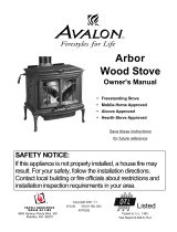
F l u s h W o o d Insert
Owner's Manual
Masonry Fireplace Insert
Save these instructions
for future reference
SAFETY NOTICE:
If this appliance is not properly installed, a house fire may
result. For your safety, follow the installation directions.
Contact local building or fire officials about restrictions and
installation inspection requirements in your area.
Travis Industries, Inc.
4800 Harbour Pointe Blvd SW
Mukilteo, WA 98275
Copyright 2007, Travis
Industries, Inc.
$10.00 100-01157
4041116
Listed
Tested to: U.L. 1482

2 Introduction
© Travis Industries 100-01157 4041116
Introduction
We welcome you as a new owner of a Travis Industries Flush Wood wood-burning fireplace insert. In
purchasing a Flush Wood you have joined the growing ranks of concerned individuals whose selection of
an energy system reflects both a concern for the environment and aesthetics. The Flush Wood is one of
the finest appliances the world over. This manual will explain the installation, operation, and maintenance
of this appliance. Please familiarize yourself with the Owner's Manual before operating your appliance
and save the manual for future reference. Included are helpful hints and suggestions which will make the
installation and operation of your new appliance an easier and more enjoyable experience. We offer our
continual support and guidance to help you achieve the maximum benefit and enjoyment from your
appliance.
Important Information
No other Flush Wood appliance has the same serial
number as yours. The serial number is stamped onto
the label on the back of the appliance.
This serial number will be needed in case you require
service of any type.
Model: Flush Wood Insert
Serial Number:
Purchase Date:
Purchased From:
Register your warranty online at:
traviswarranty.com
Or, mail your warranty card to:
Travis Industries House of Fire
4800 Harbour Pointe Blvd. SW
Mukilteo, WA 98275
Save Your Bill of Sale.
To receive full warranty coverage, you will need to
show evidence of the date you purchased your heater.
Do not mail your Bill of Sale to us.
We suggest that you attach your Bill of Sale to this
page so that you will have all the information you need
in one place should the need for service or information
occur.

Table of Contents 3
© Travis Industries 100-01157 4041116
General Information
Introduction ......................................................2
Important Information .........................................2
Safety Precautions.............................................4
Features & Specifications ....................................6
Fireplace Insert Installation
Planning The Installation .....................................7
Preparation for Installation ..............................7
Packing List.................................................7
Additional Accessories Needed for Installation ....7
Suggested Order of Installation........................7
Installation Considerations..............................8
Masonry Fireplace Requirements..........................8
Hearth Requirements .........................................8
Insert Placement Requirements ............................9
Face Dimensions...............................................9
Drafting Performance .........................................10
Leveling Bolt Installation......................................10
Flue Installation .................................................10
Block-Off Plate Installation...................................11
Surround Panel Installation ..................................12
Face Installation ................................................14
Re-Routing the Electrical Cord to the Left Side ........15
Insert with Positive Connection .............................16
Insert with Direct Connection................................16
Operating Your Appliance
Safety Notice: ...................................................17
Before Your First Fire .........................................17
Door Operation .................................................18
Bypass Operation ..............................................19
Starting a Fire ...................................................19
Adjusting the Burn Rate ......................................21
Ash Removal ....................................................21
Blower Operation ..............................................22
Re-Loading the Stove .........................................22
Overnight Burn..................................................22
Normal Operating Sounds ...................................22
Hints for Burning................................................23
Selecting Wood .................................................23
Troubleshooting ................................................24
Maintaining Your Appliance
Daily Maintenance (while stove is in use) ................25
Remove Ash (if necessary)..............................25
Clean the Glass (if necessary) .........................25
Monthly Maintenance (while appliance is in use).......26
Door and Glass Inspection ..............................26
Creosote - Formation and Need for Removal ......2
Yearly Maintenance............................................27
Touch Up Paint.............................................27
Cleaning the Air Duct and Blower .....................27
Firebrick and Baffle Inspection .........................27
Door Parts ........................................................28
Replacing the Glass.......................................28
Replacing the Door Gasket..............................28
Replacing the Door Handle..............................28
Blower and Electrical Parts ..................................29
Firebox Parts ....................................................29
Baffle Parts..................................................29
Baffle Removal .............................................29
Air Tube Removal & Replacement ....................30
Brick Removal & Replacement.................................31
Warranty
Warranty ..........................................................32
Listing Information
Listing Label .....................................................33
Index
Index ...............................................................34

4 Safety Precautions
© Travis Industries 100-01157 4041116
The viewing door must be
closed and latched during
operation.
Never block free airflow through
the air vents on this appliance.
Gas
Gasoline or other flammable
liquids must never be used to
start the fire or "Freshen Up" the
fire. Do not store or use
gasoline or other flammable
liquids in the vicinity of this
appliance.
This appliance is designed and
approved for the burning of cord
wood only. Do not attempt to
burn any other type of fuel other
than cord wood in this
appliance, it will void all
warranties and safety listings.
ASHES
Ashes must be disposed in a
metal container with a tight lid
and placed on a non-
combustible surface well away
from the home or structure.
Do not touch the appliance while
it is hot and educate all children
of the danger of a high-
temperature appliance. Young
children should be supervised
when they are in the same room
as the appliance.
36"
Keep furniture, drapes, curtains,
wood, paper, and other
combustibles a minimum of 36"
away from the front of the
appliance.
This appliance must be properly
installed to prevent the
possibility of a house fire. The
instructions must be strictly
adhered to. Do not use
makeshift methods or
compromise in the installation.
Ok
Contact your local building
officials to obtain a permit and
information on any installation
restrictions or inspection
requirements in your area.
Notify your insurance company
of this appliance as well.
Inspect the chimney connector
and chimney at least twice
monthly and clean if necessary.
Creosote may build up and
cause a house fire.
Do not connect this appliance to
any chimney serving another
appliance.
Type
HT
Clay
Liner
This appliance must be
connected to a listed high
temperature (UL 103 HT)
residential type chimney or an
approved masonry chimney with
a standard clay tile, or stainless
steel liner.

Safety Precautions 5
© Travis Industries 100-01157 4041116
Never try to repair or replace
any part of this appliance unless
instructions are given in this
manual. All other work must be
done by a trained technician.
Do not place clothing or other
flammable items on or near this
appliance.
Allow the appliance to cool
before carrying out any
maintenance or cleaning.
Do not make any changes or
modifications to an existing
masonry fireplace or chimney to
install this appliance.
Do not make any changes to the
appliance to increase
combustion air.
Maintain the door and glass seal
and keep them in good
condition.
Avoid placing wood against the
glass when loading. Do not
slam the door or strike the glass.
Overfiring the appliance may
cause a house fire. If a unit or
chimney connector glows, you
are overfiring.
This
Manual
Do not throw this manual away.
This manual has important
operating and maintenance
instructions that you will need at
a later time. Always follow the
instructions in this manual.
Do not use a grate or other
device to elevate the fire off of
the firebox floor. Burn the fire
directly on the bricks.
Travis Industries, Inc. grants
no warranty, implied or
stated, for the installation or
maintenance of your
appliance, and assumes no
responsibility of any
consequential damage(s).

6 Features & Specifications
© Travis Industries 100-01157 4041116
Installation Options:
• Masonry Fireplace Insert
WARNING: Do not install this fireplace insert into a
factory-built metal (Z.C.) fireplace.
Features:
• EPA Phase II Approved
• 2.9 Cubic Foot Firebox Volume
• Single Operating Control
• Accepts Logs Up to 24" Long
• Steel Plate Construction (5/16" & 1/4")
• Heavy Duty Refractory Firebrick
• Standard High-Tech Blower
• Five Sided Convection Chamber
Heating Specifications:
Approximate Maximum Heating Capacity (in square feet)* 1,200 to 2,000
Maximum BTU's per Hour (Cord Wood Calculation) 73,300
Overall Efficiency (Oregon Method) 71.1 %
Maximum Burn Time Up to 12 Hours
* Heating capacity will vary depending on the home's floor plan, degree of insulation, and the outside
temperature. It is also affected by the quality and moisture level of the fuel.
Dimensions:
5-5/8"
Weight 450 Lbs.
Fireplace Opening
21-1/4"
11-1/8"
1-1/4”
NOTE:
Clearances are
measured from the base
of the fireplace insert.
6" Diameter Flue Vent
20-1/2"
21-1/2"
28-7/8"
Electrical Line
(may be re-routed
to opposite side)
Figure 1
Emissions:
4.1 Grams Per Hour (EPA Phase II Approved)

Installation (for qualified installers only) 7
© Travis Industries 100-01157 4041116
SAFETY NOTICE:
Please read this entire manual before you install and use your new room heater. Failure
to follow instructions may result in property damage, bodily injury, or even death.
Contact local building or fire officials about restrictions and installation inspection
requirements in your area.
Planning The Installation
We suggest that you have an authorized Travis Industries dealer install your fireplace insert. If you
install the fireplace insert yourself, your authorized dealer should review your installation plans.
Check with local building officials for any permits required for installation of this fireplace insert and
notify your insurance company before proceeding with installation.
Preparation for Installation
• Check for damage to the exterior of the fireplace insert (dents should be reported, scratches can be
fixed by applying touch up paint).
• Check the interior of the firebox (replace cracked firebrick and make sure baffle is in place).
The fireplace insert can be lightened by removing the firebricks and baffle (pg 29) - replace before
operation.
Packing List
• Touch-Up Paint
• Leveling Bolts
• (3) Chimney Brackets with (6) Tek Self-drilling screws (for attaching the flue to the fireplace insert)
• (6) 10-24 x 1/2" Type F Screws (for surround panels)
• (7) Spring Clips (for surround panels)
• Rheostat (for blower)
• Pull Tool for Bypass
Additional Accessories Needed for Installation
1 Face (see your dealer for details - see pg 14)
2 Surround Panels (see page 12)
Suggested Order of Installation
1 Remove the firebrick and baffle components from the fireplace insert (see pages 29 and 31).
2 Place the fireplace on the hearth 12" from the fireplace (on top of cardboard to prevent
scratching). If power is on the left side, switch the power cord at this time (see page 15).
3 Install the side suround panels (see page 12).
4 Slide the insert into place (it should portrude 1-1/4" from the fireplace opening).
5 Hook up the flue (with the baffle components removed - this allows for access from within the
firebox).
6 Install the top panel and trim. Then replace the firebrick and baffle components.
7 Install the face (see page 14).

8 Installation (for qualified installers only)
© Travis Industries 100-01157 4041116
Installation Considerations
NOTE: Face Seal Connections are not allowed with this fireplace insert.
Installation Type
Considerations
Insert with Positive Flue (Full Reline)
(Page 16)
• Provides best draft
• Easiest to clean
• Easiest to install
Insert with Direct Connect Flue
(Page 16)
• Provides good draft
• Requires fireplace block-off plate - see page 11
Masonry Fireplace Requirements
• Chimney must have a clay tile liner or a stainless steel liner (positive connection)
• Entire fireplace, including chimney, must be clean and undamaged. Any damage must be repaired
prior to installation of the insert
• Chimney height: 15' minimum; 33' maximum.
• Entire fireplace, including chimney, must meet local building requirements
• Figure 2 shows the minimum size requirements for the type of fireplace used.
a
c
e
f
Masonry
Fireplace
Minimum Fireplace Size
a
b
c
d
e
f
g
h
i
j
Height (front)
Height (rear)
Width (front)*
Width (rear)
Depth
Hearth Depth
Hearth Width
Facing Width
Facing Height
Mantel Height
21-1/2"
21-1/2"
30-7/8"
21-1/4"
20-1/2"
17-1/4"
44-7/8"
46-7/8"
39"
41-1/2"
b
d
h
i
j
g
Non-Combustible Hearth
Combustible Mantel
Non-Combustible Facing
* Includes 2" for power cord.
Figure 2
Hearth Requirements
• The fireplace insert must be placed on the masonry hearth built to UBC standards.
• The non-combustible extension in front of the insert must extend 16" in front of the insert and 8" to
both sides.

Installation (for qualified installers only) 9
© Travis Industries 100-01157 4041116
Insert Placement Requirements
• The insert must be placed so that no combustibles are within, or can swing within (e.g. drapes,
doors), 36" of the front of the insert
• Insert and hearth must be installed on a level, secure floor
• The minimum clearances, facing, and hearth requirements in Figure 3 must be met.
Side
Wall
Combustible Mantel
Combustible Top Facing
Non-Combustible
Hearth
Facing
Minimum Clearances
k
l
m
n
o
p
q
x
Sidewall to Insert
Side Facing
Top Facing*
Mantel to Insert*
Hearth (Front)
Hearth (Side)
Front of Insert
Extension onto Hearth
9"
9"
39"
41-1/2"
16"
8"
36"
1-1/4"
q
l
k
p
x
o
n
m
* Measure from the base of the
fireplace insert.
Figure 3
Face Dimensions
33”
23-1/4”
33-1/2”
23-1/4”
33-3/8”
51-1/2”
Radius
23-7/8”
2-7/8”
Avalon Victorian Lace
Fireplace Xtrordinair Arched
Lopi Wilmington
Figure 4

10 Installation (for qualified installers only)
© Travis Industries 100-01157 4041116
Drafting Performance
This appliance relies upon natural draft to operate. External forces, such as wind, barometric pressure,
topography, or factors of the home (negative pressure from exhaust fans, chimneys, air infiltration, etc.),
may adversely affect draft. Travis Industries can not be responsible for external forces leading to less
than optimal performance.
Leveling Bolt Installation
Two leveling bolts are included to level the insert if the fireplace has a stepped-up hearth. To install, raise
the rear of the insert up and insert the leveling bolts into the holes in the rear corners of the insert. Adjust
the bolts until they extend the same height as the hearth steps up. After the insert is installed, fine-tune
the leveling bolts to level the insert (see Figure 5).
The leveling bolts
should stick out
this far from the
base of the insert.
Fireplace
Hearth
The leveling bolts
go into the holes
at the rear corners
of the insert.
Figure 5
Flue Installation
Included in the owner’s pack are
three “flue brackets” and six self-
drilling screws. Use these
components to secure the flue to the
fireplace insert.
Flue Opening
Flue (flexible or rigid)
Flue Bracket
Self-Drilling Screws
Figure 6

Installation (for qualified installers only) 11
© Travis Industries 100-01157 4041116
Block-Off Plate Installation
Whenever this appliance is installed with a direct connection a block-off plate, or other non-combustible
seal-off device (e.g. damper adapter), will need to be installed. This device is used to seal the chimney,
insuring no smoke enters the home and providing the chimney system with a seal to promote draft. The
directions below detail the steps for construction and installation of a block-off plate.
1. Determine a location for the block-off plate at the top of the firebox below the damper area (make it
high enough to allow installation of the connection pipe). The location should be level and in an area
where it can be mounted easily. Measure the width at the rear ("A") and front ("B") of the firebox at
the height where the block-off plate will be installed (see Figure 7). Then measure the depth of the
location where the block-off plate will be installed ("C").
2. Make a cardboard template of the measurements, but add a 2" flange to each side. This flange will
be used to mount the block-off plate to the inside of the firebox. Bend the flanges downwards on the
template and place it inside the fireplace. If the template fits correctly in its planned location, go to the
next step. If it does not, make a new template with the appropriate corrections until it fits correctly.
3. With the template in place, mark the location of the flue (see “Dimensions” on page 6). This location
approximates the center of the flue when the insert is in place (a slight offset may occur based upon
insert and block-off plate placement). Remove the template and cut a 6 1/4" diameter hole centered
on this mark.
4. Make the block-off plate of 24 gage or thicker steel to match the template. Drill two holes in each
flange for mounting the plate.
5. Mount the block-off plate using masonry screws.
6. Insulate the block-off plate using high-temperature fiberglass insulation (Kaowool® or equivalent) and
furnace cement (allow the cement to dry for at least 24 hours before burning).
7. After placing the appliance and installing the pipe through the block-off plate, use high-temperature
fiberglass insulation and furnace cement to seal any cracks between the pipe and block-off plate.
Firebox
A
C
B
See the
dimensions to
determine the
location of the
center of the
flue.
Damper
Measurement
"A"
Measurement "B"
2" Flanges
(for attaching
the block-off
plate)
Measurement
"C"
See the dimensions to determine the location of
the center of the flue.
Block-Off Plate Template
Figure 7

12 Installation (for qualified installers only)
© Travis Industries 100-01157 4041116
Surround Panel Installation
The surround panels are available in two sizes shown below.
Width Height Part#
8" Panels 45-1/2" 29-1/2" 99300240
10" Panels 49-1/2" 31-1/2" 99300241
12" Panels 53-1/2" 33-1/2" 99300242
FOR INSIDE FIT PANELS ONLY: the panels may be cut down to fit within the fireplace - see directions below.
Do not cut more than 4"
from each side panel.
The rheostat is mounted
into the side panel. It
requires 1/8" and 3/8"
diameter holes to be
drilled into the panel.
Position the rheostat a
minimum 3" away from
the insert.
4" Min.
7/16"
1. Before installing the side panels, position the insert over the hearth (not inside the fireplace). You
may wish to place something under the insert to prevent scratching (cardboard). Install the side
panels following the directions below.
Run the
rheostat wires
behind the
surround panel
(cut the lock-tie
holding them in
place).
Attach the surround panels with the 6 screws included with the fireplace insert.
HINT: Before installing the panels, pre-thread the holes in the side of the insert (use the self-
threading screws).
Run the power cord behind the surround panel
(cut the lock-tie holding it in place).

Installation (for qualified installers only) 13
© Travis Industries 100-01157 4041116
2. Install the top panel following the directions below.
Slide the top panel into place. The joggle clips on
the back of the panel insert over the tabs on the
side panel and the flange on top of the insert.
HINT: Before installing the top panel, position the insert in its final
location (1-1/4" from the fireplace opening) and attach the flue to
the insert.
3. Install the trim and rheostat following the directions below.
Trim Installation:
Insert one leg of each "L" bracket into the top and side
trim piece. Align the trim to form a precise corner, then
tighten the two set screws with a small standard
screwdriver. Slide the trim over the panels. Place the
spring clips behind the panels at the locations shown.
This keeps the trim tight against the panels.
"L" Bracket
Right Side Trim
Top Trim
Micro (1/16”)
Slotted
Screwdriver
Spring Clips
Knock-Out for Power Cord
A knock-out is provided on both sides the trim. Use pliers to remove
the knock-out. This allows the power cord to pass under the trim.
Attach the rheostat wires (orientation
does not matter).
Secure the rheostat
using the included nut
and star washer. The
knob presses into place.

14 Installation (for qualified installers only)
© Travis Industries 100-01157 4041116
Face Installation
There are several face options available for this fireplace insert. They all install with hooks that allow the
face to be hung on the fireplace insert. Follow the directions below to install the face, bypass handle, air
control handle, and door handle cover.
Face Installation:
The face has four hooks that
hang on the cast-iron tabs
near the door hinges. When
installing, make sure the
hooks insert fully and lock
into place.
Air Control Handle
Un-Screw the air control handle (with
rod) from the air control.
Install the air control knob, bypass control knob, and handle shield following the directions below.
Air Control Handle
Screw the air control handle
(with rod attached) onto the
air control.
Bypass Knob
Screw the bypass knob onto the
damper control rod.
Handle Shield Installation
Use the two nuts (included with
the face) to secure the handle
shield and emblem to the right
side handle.
NOTE:
There may be a slight gap
between the emblem and shield
after installation (this is normal).

Installation (for qualified installers only) 15
© Travis Industries 100-01157 4041116
Re-Routing the Electrical Cord to the Left Side
The power cord is connected to the right side of the insert when it leaves the factory. It may be re-routed
to the left side following the directions below. Do this procedure before installing the surround panels.
1. Disconnect the molex connector and remove the power cord following the directions below.
Power
Cord
Rheostat Wires
Disconnect the molex connector
leading from the power cord.
Use pliers to compress the strain relief
from the top and bottom while pulling it
out of the hole in the side of the insert.
Remove the power cord.
Leave the rheostat
wires in place.
Make sure the power cord is
disconnected prior to
conducting these steps.
2. Connect the power cord to the left side following the directions below.
Remove the button plug from the left side.
Re-attach the strain relief to the left side (use
pliers to compress the strain relief from the top
and bottom while pushing it into the hole).
Power
Cord
Attach the molex connector on the
power cord to the molex connector
on the left side of the insert.
ß

16 Installation (for qualified installers only)
© Travis Industries 100-01157 4041116
Insert with
Positive
Connection
NOTE:
Most factory-built
chimney manufacturers
make stainless steel
chimney liners, either
flexible or rigid. This
provides a wide variety
of installation options.
Make sure to follow the
manufacturer's
instructions for
installation and
support.
The liner must be
stainless steel
connector or flexible
vent. Follow the liner
manufacturer's
insturctions for
installation and
support.
Remove damper
or wire it open
Airtight Insulated
Clean-Out
Combustible Mantle
Flue Liner
See the section "Insert
Placement Requirements" for
minimum clearances and
hearth required.
Cap (prevents water
from entering)
Install a non-combustible
cover plate to prevent water
from entering the chimney
Surround Panels
Figure 8
Insert with Direct
Connection
NOTE:
Direct connections
require installation of
an airtight block-off
plate or damper
adapter (see "Block-off
Plate Installation" on
page 10).
Block-off plate or
damper adapter
Remove
damper
or wire it
open
Airtight
Insulated
Clean-Out
Stainless steel chimney
connector must Extend 1'
past the block-off plate or to
the flue liner
Combustible Mantle
Flue
Liner
See the section
"Insert Placement
Requirements" for
minimum clearances
and hearth required.
Surround Panels

Operating Your Appliance 17
© Travis Industries 100-01157 4041116
Safety Notice:
If this appliance is not properly installed, a house fire may result. For your safety, follow the installation
directions. Contact local building or fire officials about restrictions and installation inspection
requirements in your area.
Read and follow all of the warnings on pages 4 and 5 of this manual.
Before Your First Fire
Verify the Installation
Before starting the stove, verify that it is properly installed and all of the requirements in this manual have
been followed.
Keep all flammable materials 36" away from the front of the stove (drapes, furniture, clothing, etc.).
Curing the Paint
This heater uses a heat-activated paint that will emit some fumes while
starting the first fire. Open doors and windows to the room to vent these
fumes. This typically lasts two to four hours. You may also notice oil burning
off of the interior of the heater. This rust-stopping agent will soon dissipate.
Door Gasket - The door gasket might adhere to the paint on the front of the
heater. Leave the door slightly ajar for the first fire and be careful when
opening the door after the first fire.
2 to 4 hours
Over-Firing the Stove
This stove was designed to operate at a high temperature. But due to differences in vent configuration,
fuel, and draft, this appliance can be operated at an excessive temperature. If the stove starts to glow red
(check the faceplate or inner top), you are over-firing the stove. Shut the air control down to low and allow
the stove to cool before proceeding.
Over-firing may lead to damage of plated surfaces. If you are uncertain of over-firing conditions, we
suggest placing a stove thermometer (e.g. Rutland® Model 701) directly over the doors - temperatures
exceeding 800° are generally considered over-firing and will void the warranty.

18 Operating Your Appliance
© Travis Industries 100-01157 4041116
Door Operation
The door becomes hot during use. Use a glove to open the door if the handle is hot.
To prevent smoke from entering the room, open the bypass before opening the door (see following page
for directions). You can also open the door a small amount and let air enter the firebox.
Rotate the right door
handle down.
Swing open the right door. Swing open the left door.
Opening the Doors
Closing the Doors
Shut the left door first.
With the door handle pointing
down, swing the right door shut
NOTE: Make
sure the door
latch clears the
left side door.
Rotate the door handle
upwards to secure the
doors.

Operating Your Appliance 19
© Travis Industries 100-01157 4041116
Bypass Operation
The bypass controls the flow of smoke inside the heater. When pulled out, smoke goes directly up the
flue, creating more draft. When pushed in, the smoke goes around the baffle, utilizing the secondary
combustion and making the heater more efficient.
• When starting or re-loading, pull the bypass out.
• During normal operation, push the bypass in.
Bypass Pushed In
Used for normal operation
Bypass Pulled Out
Used for starting and re-loading
Use the included pull tool
to operate the bypass rod

20 Operating Your Appliance
© Travis Industries 100-01157 4041116
Starting a Fire
Since the dawn of time man has debated the best way to start a fire. Some use the boy-scout "tee-pee",
some prefer the "tic-tac-toe" stack. Either way, review the hints and warnings below to ensure proper fire
starting.
• Make sure the air control is pushed in and the by-pass pulled out. If additional air is needed, open the
doors 1/4" during the first five minutes of start-up.
Never use gasoline, gasoline-type lantern fuel, kerosene, charcoal lighter fluid, or similar liquids to start
or "freshen up" a fire in this stove. Keep all such liquids well away from the stove while it is in use.
If using a firestarter, use only products specifically designed for stoves - follow the manufacturer's
instructions carefully.
If the smoke does not pass up the chimney, ball up one sheet of newspaper, place it in the center of the
firebox and light it. This should start the chimney drafting (this eliminates "cold air blockage").
Use plenty of kindling to ensure the stove reaches a proper temperature. Once the kindling is burning
rapidly, place a few larger pieces of wood onto the fire.
/