
CLK TME AVG MAX TRP AVG
MPH
F
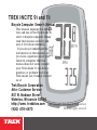
This manual explains the installa-
tion and use of the Trek Incite 9i
and 11i bicycle computer. Please
read this manual carefully and
save it for future reference.
If you do not understand the
information in this manual, or
you have a question about your
Incite 9i computer that this
manual does not cover, consult
your Trek dealer. If you have a
question or problem that your
Trek dealer can’t handle, contact
us at:
© Copyright Trek Bicycle Corporation
2006 All rights reserved

Safety and general guidelines ..................................................1
Functions ..................................................................................2
Installation ................................................................................4
Placing the computer on the handlebar ..............................5
Placing the magnet ..............................................................7
Attaching the computer wire ...............................................8
Attaching the sensors ..........................................................9
Easy setup (ReSet) ..................................................................11
ReStart- Getting ready to ride ...............................................17
Additional information ...........................................................18
Troubleshooting .....................................................................19
Replacing the battery .............................................................20
Setting custom wheel size ......................................................22
Limited Warranty ....................................................................25

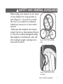
While riding your bicycle, do not stare
at the computer for long periods of
time (Figure 1). If you do not watch
the road, you could hit an obstacle,
which may cause you to lose control
and fall.
Make sure the computer wire cannot
contact the tire or wheel spokes (Figure
2). The wire could be damaged causing
the computer to malfunction. Also, the
wire could get caught, causing you to
lose control and fall.

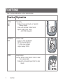
CLK
CLK
TME
AVG
MAX
TRP
ODO
MH
CLK
TME
AVG
MAX
TRP
ODO
MH

CLK
TME
AVG
MAX
TRP
ODO
MH
CLK
TME
AVG
MAX
TRP
ODO
MH

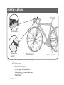
Tools needed:
• Electrical tape
• Slot-type screwdriver
• Phillips-type screwdriver
• Scissors
Stem mount
Handlebar
mount
Speed sensor
Cadence sensor

The Trek Incite 9i or 11i computer can be
mounted on the handlebar or on the stem
(Figure 3).
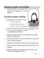
1. Select the bar clamp that fits your bike.
31.8mm bars: large clamp
25.4mm and 26.0mm: small clamp
22.2mm bar: small clamp with rubber shim
2. Insert the handlebar clamp into the back
of the computer base (Figure 4) and slide
it towards the front of the base.
3. Insert the rubber friction pad into the computer base, aligned
across the computer base.
4. With the wire pointing toward the front of the bike, wrap the bar
clamp around the handlebar.
5. Insert the screw through the washer and into the computer base.
6. Tighten the screw until the computer base cannot rotate on the
handlebar.
7. Slide the computer into the computer base until the front of the
computer and computer base line up.

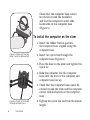
Check that the computer base cannot
be rotated around the handlebar,
and that the computer cannot slide
backwards on the computer base
(Figure 5).
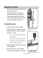
1. Insert the rubber friction pad into
the computer base, aligned along the
computer base.
2. Insert two nylon ties through the
computer base (Figure 6).
3. Place the base on the stem and tighten the
nylon tie.
4. Slide the computer into the computer
base until the front of the computer and
computer base line up.
5. Check that the computer base cannot be
rotated around the stem and the computer
cannot slide backwards on the computer
base.
6. Tighten the nylon ties and trim the excess
length.

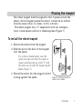
The wheel magnet must be aligned so that it passes across the
sensor. As the magnet passes the sensor, it must be no further
from the sensor than 1 to 3mm (1/32 to 1/8 inch).
The wheel magnet has a ‘T’ shaped slot with two configura-
tions: round spokes and flat or bladed spokes (Figure 7).
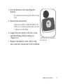
1. Remove the screw from the magnet.
2. Slide the slot in the back of the magnet
over the spoke.
For a flat or bladed spoke, start the
spoke near the end where the spoke is
round, and align the top of the ‘T’ with
the spoke as you slide the magnet up the
blade (Figure 7).
3. Thread the screw into the magnet until it
is snug against the spoke.

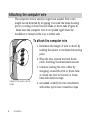
The computer wire is usually longer than needed. Extra wire
length can be diverted by wrapping it around the brake housing
prior to routing it down the fork blade or down tube (Figure 8).
Make sure the computer wire is not pulled tight when the
handlebar is turned all the way to either side.
1. Determine the length of wire to divert by
holding the sensor at its desired mounting
point.
2. Wrap the wire around the front brake
cable, diverting the determined amount.
3. Continue routing the wire, either by
wrapping around the fork or frame tube,
or attach the wire to the fork or frame
tube with electrical tape.
4. As needed, solidify the wire attachment
with either nylon ties or electrical tape.

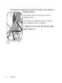
The magnet must pass across the line on
the sensor (Figure 9).
These instructions are written for
the front wheel, but apply equally to
installing the magnet and cadence
sensor which go on the left crank and
the frame’s chainstay (Figure 10).
1. Align the sensor with the magnet.
2. Orient the sensor so that the clearance
between the sensor and the magnet is
between 1 to 3mm.
The sensor can be rotated around the fork
about 45 degrees.
If needed, the sensor and magnet can be
moved up or down the spoke and fork to
change the amount of clearance.
3. Attach the sensor with nylon ties, but do
not fully tighten.
4. With the computer in the computer
base, check the alignment of the sensor
1.0 -
3.0mm

and magnet by spinning the wheel and noting if the computer is
displaying speed.
If the computer shows current speed, the sensor is
reading the magnet.
If the computer is not displaying a value, realign the
sensor and magnet until one is displayed.
5. Tighten the nylon ties and trim the excess
length (Figure 11).

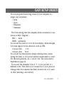
You can program the starting values of your computer in a
single, easy procedure:
• Units
• Clock
• Wheelsize
• Odometer
The Units setting tells the computer which conversion to use:
metric or SAE (“English”):
MH = miles
KMH = kilometers
You can set the clock for 12 or 24 hour display, which changes
how time appears in the afternoon, such as 3PM:
12 hour clock 3:00
24 hour clock 15:00
You can set the wheel size by simply choosing from a menu
listing tire sizes, or you can set custom values listed in a chart.
For the most precision, do a “rollout” test. The rollout test is
described on page 22.
You can set the odometer to be at “0” or you can start at a
different value. This allows you to keep track of your previous
mileage after the computer has Reset (started over at 0), such
as after installing a new battery.

CLK TME AVG MAX TRP AVG
MPH
F
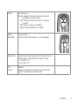
Mode
Set
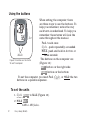
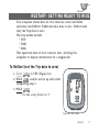
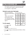
When setting the computer, there
are three ways to use the buttons. To
help you remember, notice the way
each term is underlined. To help you
remember, these terms will look the
same throughout the manual.
Push- touch once
Cycle - push repeatedly as needed
Hold- push and hold in for two or
three seconds
The buttons on the computer are
(Figure 12):
Set• button on the right side
Mode button on the bottom
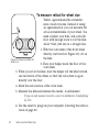
To set the computer, you must Push, Cycle, or Hold the two
buttons in a specific sequence.
1. Cycle Mode to MAX (Figure 12).
2. Hold Set•
KMH or MH flashes.

CLK
TME
AVG
MAX
TRP
ODO
MH
Mode
Set
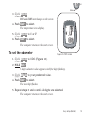
3. Cycle Mode
MH and KMH interchange on the screen.
4. Push Set• to select.
The temperature icon display.
5. Cycle Mode to C or F
6. Push Set• to select.
The computer returns to the start screen.
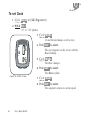
1. Cycle Mode to ODO (Figure 13).
2. Hold Set•
5-digit odometer value appears with first digit flashing.
3. Cycle Mode to your preferred value.
4. Push Set• to select.
The next digit flashes.
5. Repeat steps 3 and 4 until all digits are selected.
The computer returns to the start screen.
CLK TME ODO MAX TRP AVG
MPH
F

CLK
TME
AVG
MAX
TRP
ODO
MH
Mode
Set
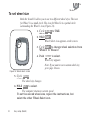
Both the 9i and 11i allow you to use two different wheel sizes. The icon
for Wheel 1 is a small circle. The icon for Wheel 2 is a partial circle
surrounding the Wheel 1 icon (Figure 14).
1. Cycle Mode to TME.
2. Hold Set•
Wheel Select icon appears on the screen.
3. Cycle Set• to change wheel selection from
Wheel 1 to Wheel 2.
4. Push Mode to select.
Wheel size appears.
Note: If you want to set a custom wheel size,
go to page 24 now.
5. Cycle Mode
The wheel size changes.
6. Hold Set• to select.
The computer returns to current speed.
To set the second wheel size, repeat the instructions, but
select the other Wheel Select icon.

CLK
TME
AVG
MAX
TRP
ODO
MH
Mode
Set
1. Cycle Mode to TRP
2. Hold the left Mode and the right Mode together.
The Wheel Select icon changes (Figure 14). Repeat step 2 to change
again.

CLK
TME
AVG
MAX
TRP
ODO
MH
Mode
Set
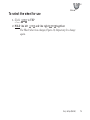
1. Cycle Mode to CLK (Figure 15).
2. Hold Set•
“12” or “24” flashes.
CLK TME AVG MAX TRP AVG
MPH
F
3. Cycle Mode
12 and 24 interchange on the screen.
4. Push Set• to select
The clock appears on the screen with the
Hour flashing.
5. Cycle Mode
The Hour changes.
6. Push Set• to select.
The Minutes flash.
7. Cycle Mode
8. Push Set• to select.
The computer returns to current speed.

CLK
TME
AVG
MAX
TRP
ODO
MH
Mode
Set
Your computer stores data for two intervals- since last ReSet
and since last ReStart. ReSet sets ALL data to zero. ReStart sets
only the Trip data to zero.
The trip modes include
• TRP
• TME
• MAX
This operation sets all four values to zero, allowing the
computer to display information for a single ride.
1. Cycle Mode to TRP (Figure 16).
2. Hold Set•, and do not let up until after
completing step 3.
3. Hold Mode.
The Max setting ReStarts at ‘0’.
CLK TME AVG MAX TRP AVG
MPH
F

CLK
TME
AVG
MAX
TRP
ODO
MH
Mode
Set
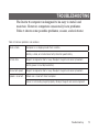
Once the computer is programmed and installed, it is very easy
to use. To change to different modes (functions), simply Cycle
the Mode button until the desired function appears, shown by
the spelled name of the function.
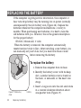
The computer is held on its base by a flexible snap. To remove
the computer, press firmly on the computer (not on the base) in
a rearward direction.
Bicycle computers function on electricity. If the electrical
contacts between the computer and its base become saturated,
the electrical signals may become irregular or interrupted
entirely. If the computer is to be used in heavy rain, etc., we
recommend that a plastic bag be put over the computer and its
base. The other parts of the computer system are waterproof.
Page is loading ...
Page is loading ...
Page is loading ...
Page is loading ...
Page is loading ...
Page is loading ...
Page is loading ...
-
 1
1
-
 2
2
-
 3
3
-
 4
4
-
 5
5
-
 6
6
-
 7
7
-
 8
8
-
 9
9
-
 10
10
-
 11
11
-
 12
12
-
 13
13
-
 14
14
-
 15
15
-
 16
16
-
 17
17
-
 18
18
-
 19
19
-
 20
20
-
 21
21
-
 22
22
-
 23
23
-
 24
24
-
 25
25
-
 26
26
-
 27
27


Trek 11i User manual
- Category
- Bicycle accessories
- Type
- User manual
Ask a question and I''ll find the answer in the document
Finding information in a document is now easier with AI


