
MODEL PS-31
Power Supply
User Manual
9300-4437-00 Rev J 12/2007
POWER
THERMAL
OVERLOAD
321
FAULT
AUDIBLE
ALERT
ON
CHANNEL STATUS
PROGRAM
LEVEL
CHANNEL
ASSIGN
1
2
3
TW INTERCOM SYSTEM
POWER SUPPLY
PS31
RTS SYSTEMS

PROPRIETARY NOTICE
The product information and design disclosed herein were originated by
and are the property of Telex Communications, Inc. Telex reserves all
patent, proprietary design, manufacturing, reproduction, use and sales
rights thereto, and to any article disclosed therein, except to the extent
rights are expressly granted to others.
COPYRIGHT NOTICE
Copyright 2007 by Telex Communications, Inc. All rights reserved.
Reproduction, in whole or in part, without prior written permission from
Telex is prohibited.
WARRANTY NOTICE
See the enclosed warranty card for further details.
CUSTOMER SUPPORT
Technical questions should be directed to:
Customer Service Department
RTS/Telex Communications, Inc.
12000 Portland Avenue South
Burnsville, MN 55337 USA
Telephone: 800-392-3497
Fax: 800-323-0498
RETURN SHIPPING INSTRUCTIONS
Customer Service Department
Telex Communications, Inc. (Lincoln, NE)
Telephone: 402-467-5321
Fax: 402-467-3279
Factory Service: 800-553-5992
Please include a note in the box which supplies the company name,
address, phone number, a person to contact regarding the repair, the type
and quantity of equipment, a description of the problem and the serial
number(s).
SHIPPING TO THE MANUFACTURER
All shipments of product should be made via UPS Ground, prepaid (you
may request from Factory Service a different shipment method). Any
shipment upgrades will be paid by the customer. The equipment should
be shipped in the original packing carton. If the original carton is not
available, use any suitable container that is rigid and of adequate size. If
a substitute container is used, the equipment should be wrapped in paper
and surrounded with at least four (4) inches of excelsior or similar
shock-absorbing material. All shipments must be sent to the following
address and must include the Proof of Purchase for warranty repair.
Upon completion of any repair the equipment will be returned via
United Parcel Service or specified shipper, collect.
Factory Service Department
Telex Communications, Inc.
8601 East Cornhusker Hwy.
Lincoln, NE 68507 U.S.A.
Attn: Service
This package should include the following:

Table
of
Contents
DESCRIPTION .................................................1
DESCRIPTION .......................................................1
GENERAL ...................................................................1
FEATURES .................................................................1
S
TATUS INDICATORS ....................................................2
I
NPUT POWER ..............................................................2
I
NTERCOM CHANNEL CONNECTIONS ..........................2
I
MPEDANCE SELECTION ..............................................2
Installation ..............................................................3
MECHANICAL INSTALLATION ................................3
ELECTRICAL INSTALLATION ..................................3
OPERATION .....................................................5
POWER-UP INDICATIONS ...................................5
FAULT INDICATIONS ...........................................5
THERMAL OVERLOAD .........................................5
IMPEDANCE SELECT SWITCHES .......................5
PROGRAM INPUT .................................................5
THEORY OF OPERATION .............................7
GENERAL ...............................................................7
AC TO DC CONVERSION .....................................7
IMPEDANCE GENERATOR ..................................7
PROGRAM INSERTION AMPLIFIER ...................8
DISPLAY AND DIAGNOSTIC CIRCUITRY ..........8
CHANNEL STATUS INDICATORS ............................8
FAULT INDICATOR ...................................................8
THERMAL OVERLOAD .............................................8
MAINTENANCE .............................................11
INTRODUCTION .................................................11
GENERAL MAINTENANCE ................................11
SAFETY CONSIDERATIONS .................................. 11
ACCESS ....................................................................11
CLEANING ............................................................... 11
INPUT POWER SELECTION .................................. 12
CHANNEL DC OUTPUT FUSE REPLACEMENT . 12
TEST PROCEDURES ...........................................12
TEST EQUIPMENT ..................................................12
INITIAL INSPECTION .............................................12
POWER-UP TEST .................................................... 12
POWERED CHANNEL TEST .................................. 13
FUNCTIONAL TEST OF ALL OUTPUTS ............... 14
4.4 TROUBLESHOOTING ....................................... 15
REPLACEMENT PARTS ...............................17
WHERE TO OBTAIN PARTS ...............................17
MECHANICAL PARTS .......................................18
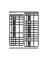
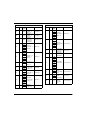
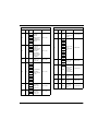
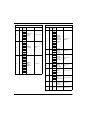
ELECTRICAL PARTS .........................................19
DIAGRAMS AND SPECIFICATIONS ..........25
Specifications ........................................................33


1
CHAPTER 1
DESCRIPTION
DESCRIPTION
GENERAL
The Model PS31 supplies 32 volts regulated DC power to each of three intercom channels. It has short circuit and thermal
overload protection, with automatic recovery when the fault is removed.
FEATURES
Program Input
There is a PROGRAM INPUT connector on the rear panel. A CHANNEL ASSIGN switch on the front panel assigns the
program to any of the three channels. A LEVEL control adjusts the program level to the intercom channel.

2
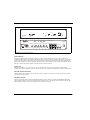
Status Indicators
There is an audible alarm and a red FAULT indicator for current overload indication on any of the three channels. An
AUDIBLE ALERT switch on the front panel turns the alarm on or off, but the FAULT indicator will continue to flash during
current overload conditions. There is also a green status indicator for each channel. Each of these indicators will remain lit
during normal operation, but will turn off during a channel current overload condition. Output current is automatically reduced
during an overload, and normal operation is restored when the overload is removed.
Input Power
The PS31 is available in two versions: one for 115 VAC operation and one for 230 VAC operation. A simple internal
modification changes the operating voltage for 100 VAC or 200 VAC. A POWER on/off switch is provided on the front panel.
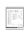
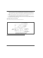
Intercom Channel Connections
Intercom channels are connected to the rear panel of the PS31. A variety of connector pin-outs is provided to accommodate
individual system requirements.
Impedance Selection
The PS31 provides the required channel terminating impedance for each channel. A 200/400 ohm IMPEDANCE SELECT
switch for each channel is located on the rear panel. These switches are set to 200 ohms for normal operation. The 400 ohm
setting permits two PS31's to be coupled to double the DC capacity of the system.
FIGURE 1. PS-31 Front and Back View
TELEX COMMUNICATIONS, INC.
MADE IN USA
TW INTERCOM SYSTEM
POWER SUPPLY
MODEL PS 31
NOTE
INTERNALLY
FUSED
CONNECTOR
PIN-OUT CODE
CH1-2
PIN - 1 COM
PIN - 2 CH 1
PIN - 3 CH 2
CH1-3
PIN - 1 COM
PIN - 2 CH 1
PIN - 3 CH 3
CH2-3
PIN - 1 COM
PIN - 2 CH 2
PIN - 3 CH 3
CH1-2-3
PIN - 1
PIN - 2 CH 2
PIN - 3 CH 3
PIN - 4 COM
CH 1
OUTPUTS CONNECT TO
TW INTERCOM SYSTEM COMPONENTS
REFER TO OPERATION MANUAL
OUTPUTS
IMPEDANCE SELECT
CHANNEL
CH 1-2-3 CH 1-2-3
CH 1-2-3
PUSH
12
3
J107
J108
J109
J110
J111
AC POWER
J101 J102 J103 J104 J105 J106
CH 2-3CH 2-3CH 1-3CH 1-3CH 1-2CH 1-2
PROGRAM INPUT
Z = 10K BALANCED
PIN 1 - GROUNDED
PIN 2 - LO
PIN3-HI
400
DUAL
200
NORM
W
W
CAUTION
WARNING
- TO REDUCE THE RISK OF FIRE, REPLACE ONLY WITH SAME TYPE FUSE
- TO REDUCE THE RISK OF FIRE OR ELECTRIC SHOCK, DO NOT EXPOSE THIS APPLIANCE TO RAIN OR MOISTURE
POWER
THERMAL
OVERLOAD
321
FAU LT
AUDIBLE
ALERT
ON
CHANNEL STATUS
PROGRAM
LEVEL
CHANNEL
ASSIGN
1
2
3
TW INTERCOM SYSTEM
POWER SUPPLY
PS31
RTS SYSTEMS

3
Installation
MECHANICAL INSTALLATION
The Model PS31 can be rack mounted or used free standing. The rack mount is a standard 19-inches wide by 3.5-inches high.
Allow room for cable connections.
ELECTRICAL INSTALLATION
CONNECTING INTERCOM STATIONS
NOTE: When connecting intercom stations, do not exceed the power supply capacity, either for one channel or for all
three channels. Power supply capacity is graphically illustrated in Figure 1. If more capacity is required, refer to
“PS 31 Capacity” on page 4.
Connect intercom channels to the OUTPUTS connectors on the rear panel. Pin assignments are printed above the connectors.
These connectors provide three alternatives for intercom channel connection:
• Connectors J101 through J106 can be used to connect various combinations of two channels.
• Connectors J107 and J108 can be used to connect all three channels.
• Connector J109 can also be used to connect three channels, but unlike all the other connectors, no power is
supplied at this connector. This connector can be used to interconnect the audio channels when using two PS31
power supplies.
USING TWO PS31'S TO EXPAND CAPACITY
If there are more stations on one or more channels than the power supply capacity will allow, two PS31 power supplies may be
used to double capacity. For each channel that requires added capacity:
1. Use the J109 connectors on both power supplies to interconnect the audio and ground pins of the desired channel (See
“PS-31 Front and Back View” on page 2.).
2. Divide the stations that you wish to connect into two groups. Connect one group to the first power supply. Connect
the other group to the second power supply. For each group, do not exceed the capacity (either total or per channel) of
the power supply.
3. On both power supplies, set the IMPEDANCE SELECT switches for the channel to the 400<F128M>W<F255D>
DUAL position. (Leave all impedance switches for channels that are not interconnected in the
200<F128M>W<F255D> NORM position.
PROGRAM INPUTS
A program source may be connected to the PROGRAM INPUT connector on the rear panel. Pin assignments are printed above
the connector (See “PS-31 Front and Back View” on page 2.).
To connect an unbalanced program source, connect pin 2 to to pin 1. Then connect program ground to pin 1 and program HI to
pin 3.
If two PS31's are interconnected, a separate program source may be connected to each.
AC POWER
Plug the AC power cord into the PS31 and into an AC mains outlet.

4
NOTE: The PS31 is factory-set for either 110-120-volt operation or 220-240-volt operation. The operating voltage is
indicated on the back of the unit. Operation at 100-110 volts or 200-220 volts requires an internal modification.
Refer to “MAINTENANCE” on page 11.
FIGURE 2. PS 31 Capacity

5
CHAPTER 2
OPERATION
POWER-UP INDICATIONS
Turn on the POWER switch. During normal operation the three CHANNEL STATUS indicators should be lit and the FAULT
and THERMAL OVERLOAD indicators should be off.
FAULT INDICATIONS
If there is a fault on a channel, the CHANNEL STATUS indicator for that channel will turn off and the red FAULT indicator
will flash. If the AUDIBLE ALERT is set to “ON”, the alarm will beep. Possible causes of a fault include: overvoltage,
overcurrent, short circuit to ground or severe brown-outs.
THERMAL OVERLOAD
If the PS31 overheats, the THERMAL OVERLOAD indicator will turn on and AC power to the PS31 will be shut off. Normal
operation will resume when the PS31 cools. Possible causes of a thermal shut-down include overloading the output channels
or improper internal mains voltage selection.
IMPEDANCE SELECT SWITCHES
The IMPEDANCE SELECT switches on the rear panel allow each channel to be set for 200 ohm or 400 ohm operation. Select
200<F128M>W<F255D> NORM for each channel operated independently. Select 400<F128M>W<F255D> DUAL for each
channel connected to another channel through the AUDIO ONLY connector (J109). Figure 1, “PS-31 Front and Back View,”
on page 2
PROGRAM INPUT
If a program source is connected to the PROGRAM INPUT connector on the back of the PS31, it may be routed to any one of
the intercom channels using the CHANNEL ASSIGN switch. Use the LEVEL control to adjust the program level on the
selected channel.

6

7
CHAPTER 3
THEORY OF OPERATION
GENERAL
The PS31 electronic circuits include an AC to DC converter, an impedance generator for each channel, a program insertion
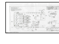
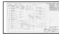
amplifier, and display and diagnostics circuits (Figure 3 on page 9). The following paragraphs describe these circuits. For
schematic reference, see drawing SD3225 in Chapter 7.
AC TO DC CONVERSION
Transformer T101 steps down the AC mains voltage to 33 volts rms. Diodes D101-D104 rectify this voltage and capacitor
C117 filters out the AC component, leaving about 45-50 volts unregulated DC. This raw DC voltage feeds the impedance
generators (through fuses F201, F301, and F401), and regulator U101.
U101 provides regulated 30 volts DC. This voltage is supplied to the impedance generators, to the program insertion amplifier,
and to U102. Diodes D109 and D110 protect U101. Resistors R107 and R108 establish the output voltage reference of 30 volts
DC. Capacitor C121 reduces the amount of ripple on the 30 volts DC, and C122 provides decoupling.
U102 provides regulated 7.5 volts DC. This voltage is used as a reference level by the program insertion amplifier. It also
powers the display circuits. Diodes D111 and D112 protect U102. Resistors R109 and R110 establish the output voltage
reference of 7.5 volts. Capacitor C123 reduces the amount of ripple on the 7.5 volts DC and C124 filters the output.
IMPEDANCE GENERATOR
There is a separate impedance generator for each channel. The impedance generator supplies regulated 32 volts DC to the
channel and also provides the channel terminating impedance. The following paragraphs describe the impedance generator for
channel 1. Other channels are identical.
Diodes D202 and D201 and resistors R202 and R201 divide the raw DC for the variable DC reference. This variable DC
reference allows the quiescent output voltage of the regulators to follow the rms value of the AC mains voltage. Capacitors
C202, C203 and C204 and resistors R203 and R206 are a low pass filter for the variable DC reference and provide fast start up
response time. Integrated circuit U202B, resistors R214, R215 and R217 and capacitors C210 and C207 amplify and buffer the
variable DC reference. Resistor R213 and capacitor C209 decouple the supply voltage for integrated circuit U202. Resistors
R211 and R208 set the amount by which the output voltage of the regulator exceeds the variable DC reference. R205 sinks the
quiescent current from R208. Diode D203 clamps excessive output voltage of the regulator due to transients while diodes
D204 and D206 protect the regulator from reversed voltages due to shorts on the output line.

8
Resistors R219 and R221 sense the output current from the regulators into the RTS line. Integrated circuit U202A, together
with capacitors C212 and C214 and resistors R220, R225, R223, and R216 differentially amplify this output current and feed
it back to the adjust terminal of the regulators to create the audio impedance. Diodes D207, D208, D211, D212, D209, and
D210 clamp the audio output voltage to avoid over-driving the RTS line and allow fast recovery from large transients.
Diode D214 protects the impedance generator from an over voltage on the RTS line. Capacitor C215 is an RF bypass and
resistor R227 biases diode D214 on with 10 mA of current for “dry line” operation. Toggle switch S201, located on the rear
panel selects an output impedance of 200 or 400 ohms. Since the impedance generator operates at 400 ohms, toggle switch
S201 shunts the output with 390 ohms for a 200 ohm output.
PROGRAM INSERTION AMPLIFIER
The program-insertion amplifier circuitry accepts balanced or unbalanced input from any source and injects this input, via a
bilateral current source, onto the RTS line.
Program audio, present at connector J110, rear panel, is applied via input isolation transformer T103 to PROGRAM LEVEL
potentiometer R111. Resistor R606 and capacitor C601 provide RF suppression. Integrated circuit U601a, capacitor C602 and
resistors R603 and R602 amplify the input and provide a low impedance drive for the following stage. Integrated circuit
U601b, capacitor C606 and resistors R604, R607, R609, R605, and R608 form the bilateral current source which turns the
input voltage into an output current. Capacitors C604, C605 and resistor R610 blocks any DC potential on the RTS line.
Diodes D601 and D602 protect integrated circuit U601 from transients and resistor R601 and capacitor C603 decouple the
power to integrated circuit U601.
DISPLAY AND DIAGNOSTIC CIRCUITRY
The display and diagnostic circuits detect fault conditions and warn the user with front panel lights and an audio indicator.
CHANNEL STATUS INDICATORS
(The channel status indicator for channel is described. The channel status indicators for channels 2 and 3 are identical.)
As long as the output voltage on channel 1 is above approximately 21 VDC, diode D205 will conduct causing transistor Q201
to be on, which turns on DS201, the CHANNEL 1 STATUS LED on the front panel. If the channel 1 voltage drops below
approximately 21 volts, transistor Q201 shuts off, LED DS201 goes dark, and the fault indicator circuitry is notified through
diode D215.
FAULT INDICATOR
If pin 5 of integrated circuit U103 is driven high by an under-voltage condition on any channel, the flasher circuit, which
consists of half of integrated circuit U103, capacitor C126 and resistors R116 and R117, will flash the FAULT indicator LED,
DS101, and pulse the audible alarm circuit. The audible alarm oscillator consists of the other half of integrated circuit U103,
capacitor C127 and resistors R120 and R121.
THERMAL OVERLOAD
Switch S101 is a thermal sensing switch connected in series with the power switch. It is attached to the power transformer,
T101. The front panel THERMAL OVERLOAD indicator, DS5, is connected across S101. If the transformer temperature
remains below approximately 75 C, S101 will remain closed, and there will be no voltage drop across DS5. If the transformer
temperature rises above 75 C, S101 will open and remove AC primary power to T101. The AC voltage will be developed
across DS5 and it will light.

9
FIGURE 3. Block Diagram

10

11
CHAPTER 4
MAINTENANCE
INTRODUCTION
This section provides service information for normal maintenance, factory performance tests and troubleshooting tips.
GENERAL MAINTENANCE
SAFETY CONSIDERATIONS
Service and adjustments should be performed only by qualified service personnel.
Any adjustment, maintenance, and repair of the opened equipment while any power or voltage is applied should be avoided as
much as possible, and should be carried out only by a skilled person who is aware of the hazard involved.
It is possible for capacitors inside the equipment to still be charged even if the equipment has been disconnected from its
power source.
Be certain that only fuses with the required current rating and of the specified type (fast blow, time delay, slow blow, etc.) are
used for replacement. The use of repaired fuses and the short-circuiting of fuse holders must be avoided.
ACCESS
To get inside the Model PS31, remove the screws on the top and bottom covers. Slide covers off toward the back of the unit.
CLEANING
Clean the outside of the Model PS31 with denatured alcohol or a mild solution of detergent and water. Clean the interior with
dry, low pressure air. The circuit boards can be cleaned with 1,1,1 trichloroethane or Freon TF. Do not allow these or any
solvents to get into any potentiometers.

12
INPUT POWER SELECTION
CAUTION: These maintenance instructions are for qualified personnel only. To avoid electric shock, do not perform any
servicing unless qualified to do so. Disconnect AC power before servicing.The Model PS31 operates on 100,
120, 200, or 240 volts AC at 50/60 hertz, depending on the internal power settings. To convert from one mains
voltage to another, remove the covers and set the internal switch, jumpers and use the proper rear panel fuse as
specified in Table 3. (The switch and jumpers are located on the circuit board next to the power transformer
connector.)
CHANNEL DC OUTPUT FUSE REPLACEMENT
To replace channel fuses (F201, F301, F401), remove covers. These fuses are located on the circuit board.
TEST PROCEDURES
TEST EQUIPMENT
•
An isolated, variable voltage power transformer with voltage and current metering ("VARIAC",
"POWERSTAT", or equivalent)
• A sine wave oscillator
• An oscilloscope, 15 megahertz minimum bandwidth
• A distortion analyzer (HP331 through HP334, HP339, or equivalent)
• An AC voltmeter capable of reading volts, dBm and dBu
• Two DC voltmeters
• A test load (see Figure 4)
• A capacitive load box (see Figure 5)
• A program input cable (see Figure 6)
• Two channel output cables (see Figure 7)
INITIAL INSPECTION
Verify electrical orientation of power supply capacitors. Verify proper wiring of transformer primary for local mains voltage.
Verify that the proper fuses are installed in the back panel fuse holder and on the printed circuit board. Check that the
transformer is securely mounted and that it is electrically isolated from the chassis (resistance from chassis to transformer core
should be greater than 10 kohms). Check that the power supply capacitor is securely fastened. Using an ohmmeter, verify that
the chassis is electrically connected to the grounding pin on the power connector (less than 0.2 ohm).
POWER-UP TEST
1. Set the variable voltage power transformer to off, and set the voltage to zero.
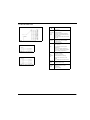
TABLE 1. Voltage Selection
AC Source
S107
Setting
Jumpers Rear
Panel
Fuse
Add Remove
100 VAC 115 W2, W3 W1, W4 3A
120 VAC 115 W1, W4 W2, W3 3A
200 VAC 230 W2, W3 W1, W4 1.5A
240 VAC 230 W1, W4 W2, W3 1.5A

13
2. Plug the PS31 into the variable voltage power transformer.
3. Set the PS31 POWER switch to ON.
4. Set the PS31 AUDIBLE ALERT switch to ON.
5. Turn on the variable voltage power transformer.
6. Slowly turn up the voltage. Watch for excessive sustained current consumption above 1 ampere. While the voltage is
being increased, the audible alert indicator should sound and the FAULT light should flash. Stop increasing the
voltage when the standard operating voltage level is reached.
7. Set the AUDIBLE ALERT switch to off.
8. Turn the PS31 POWER switch off: the STATUS lights should fade, and finally, the FAULT light should blink. The
audible alert should not sound.
9. Turn the POWER switch back on.
10. Turn the AUDIBLE ALERT switch on.
POWERED CHANNEL TEST
The following procedure tests channel 1. Repeat for channels 2 and 3.
1. Connect the DC meters and capacitive load to the test load as shown in Figure 5-1.
2. Set the capacitive load to OFF.
3. On the test load, set the output current potentiometer in the fully CCW position (minimum output load).
4. Plug one of the four-wire channel output cables into J108 on the PS31. This will be the powered output cable
5. Connect the ground lead of the powered output cable to the test load ground terminal.
6. Connect channel 1 of the powered output cable to the powered channel terminal of the test load.
7. Connect the second four-wire output cable to J109 on the PS31. This will be the AUDIO ONLY output cable.
8. Connect channel 1 and ground of the audio only output cable to the distortion analyzer input and to the AC voltmeter.
9. Connect the program input cable to the PS31 PROGRAM INPUT (J110) and to the sine wave oscillator.
10. On the PS31, set the PROGRAM CHANNEL ASSIGN switch to channel 1. Turn the PS31 PROGRAM LEVEL
control fully CCW (minimum level).
11. Set the sine wave oscillator for 1 kilohertz, 0.10 volt rms at the PROGRAM INPUT of the PS31.
12. Observe the DC output voltage on DC voltmeter 1. It should be between 31.0 and 32.5 volts DC.
13. Set the output current adjustment control on the test load so that the output current is 0.50 amperes (0.5 volts at DC
voltmeter 2). The output voltage at voltmeter 1 should drop by 0.5 volts or less.
14. Adjust the PS31 PROGRAM LEVEL control fully CW (maximum level). The AC voltage should be 1.8 volts rms.
15. Adjust the PROGRAM LEVEL control until the AC voltmeter reads 1.0 volt rms. The waveform on the scope should
be a sine wave with no hum or distortion.
16. Set the capacitive load box switch to 100 pF. The waveform on the scope should remain unaffected. Repeat this step
for all the positions of the switch. The only noticeable effect should be waveform attenuation with the higher
capacitance values.
17. Set the capacitive load to OFF.
18. Set the oscillator frequency to 10 kilohertz (the oscillator level should remain constant). The AC voltage should read
between 0.79 and 1.0 volts rms.
19. Set the oscillator frequency to 100 hertz (the oscillator level should remain constant). The AC voltage should read
between 0.71 and 0.89 volts rms. Return the oscillator frequency to 1 kilohertz.
20. Place a 200-ohm resistor across the distortion analyzer input. The AC voltmeter should read from 0.45 to 0.55 volts
rms. Remove the 200-ohm resistor.
21. Short the POWERED CHANNEL terminal of the test load to the SHORTING TERMINAL on the test load. The
output short circuit current should be 0.5 amp (0.5 volts at DC voltmeter 2), 30%. The channel 1 STATUS light
should be extinguished, the FAULT light should be flashing, and the audible alert should sound. Remove the short.
The FAULT light should go out and the channel 1 STATUS light should turn on.

14
22. On the test load, slowly turn the output current adjustment control CW. The output current (as measured at DC
voltmeter 2) should slowly increase. The FAULT light and audible alert should again come on as the output voltage
drops below approximately 21 volts (measured at DC voltmeter 1). The current will reach a maximum fold-back
value of 2.0 amps (2.0 volts on voltmeter 2), 30% before falling very suddenly back to the short circuit value of 0.5
amps.
23. Turn the output current adjustment control on the test load fully CCW. The AC voltmeter should still read 1.0 to 1.1
volts rms and the waveform on the oscilloscope should be a sine wave free from distortion.
24. Turn the PROGRAM LEVEL control fully CCW. Read the hum and noise on the distortion analyzer meter using a
low pass filter on the analyzer (approximately 30 kilohertz). The hum and noise should be less than 1.0 millivolt rms.
25. Repeat tests for PS31 output channels 2 and 3.
FUNCTIONAL TEST OF ALL OUTPUTS
Plug a user station into each output connector. Verify that each station works.
FIGURE 4. Test Load

15
4.4 TROUBLESHOOTING
Figure 2. Capacitive Load Box
Figure 3. Program Input Cable
Figure 4. Channel Output Cable
Proble
m
Check
No Output
& No
Lights
Plug, power
Fuse, back panel (F105)
Voltage Selection
Excessive transformer temperature
(thermal cut-out will self reset after a
cooling period.
Raw DC supply voltage (should be 45-
50 volts)
No
Program
Input Connections
Input LEVEL control CHANNEL
ASSIGN switch
Hum
Input Connections
Intercom cable routing (too close to
AC, lights, etc.)
User station too close to a power
transformer.
PS31 common lead connected to a
“humming” chassis ground someplace.
Mains voltage wiring incorrect.
Fault
indicator
ON
Short on intercom channel
Channel overloaded
“Brown-out” on mains
Voltage selection is set wrong
Brown fuse on PCB (F201, F301,
F401)
DC voltage output (32 volts nominal)
Status OK,
Yet NO
Output
Check for AC on RTS line due to
faulty power line wiring
Distorted
Sound
Input connections
PROGRAM LEVEL control
Termination
DC line voltage

16
Page is loading ...
Page is loading ...
Page is loading ...
Page is loading ...
Page is loading ...
Page is loading ...
Page is loading ...
Page is loading ...
Page is loading ...
Page is loading ...
Page is loading ...
Page is loading ...
Page is loading ...
Page is loading ...
Page is loading ...
Page is loading ...
Page is loading ...
Page is loading ...
-
 1
1
-
 2
2
-
 3
3
-
 4
4
-
 5
5
-
 6
6
-
 7
7
-
 8
8
-
 9
9
-
 10
10
-
 11
11
-
 12
12
-
 13
13
-
 14
14
-
 15
15
-
 16
16
-
 17
17
-
 18
18
-
 19
19
-
 20
20
-
 21
21
-
 22
22
-
 23
23
-
 24
24
-
 25
25
-
 26
26
-
 27
27
-
 28
28
-
 29
29
-
 30
30
-
 31
31
-
 32
32
-
 33
33
-
 34
34
-
 35
35
-
 36
36
-
 37
37
-
 38
38


Ask a question and I''ll find the answer in the document
Finding information in a document is now easier with AI
Related papers
Other documents
-
 T'nB CSSTGN Datasheet
-
 Audiocom PS-4001 Specification
-
Broan U10230SBI Specification
-
Rockville RXC2D Owner's manual
-
Hitachi Universal Storage Platform VM Installation Planning Manual
-
 StudioTech M46-00180 User manual
-
Telex Power Supply PS-4001 User manual
-
-
Panasonic WV-V3 User manual
-
 Zvox Audio SB700 Setup & Operation


