Page is loading ...

FOR YOUR SAFETY
• Do not store or use gasoline or other
flammable vapours and liquids in the
vicinity of this or any other
appliance.
• Installation and service must be
performed by a qualified installer,
service agency or the gas supplier.
GAS FIRED WATER HEATER
INSTALLATION AND OPERATING INSTRUCTIONS
Read these instructions thoroughly before starting
WHAT TO DO IF YOU SMELL GAS?
• Do not try to light any appliance.
• Do not touch any electrical switch; do
not use any phone in your building.
• Immediately call your gas supplier
from a neighbor’s phone. Follow the
gas supplier’s instructions.
• If you cannot reach your gas supplier,
call the fire department.
TABLE OF CONTENTS
I) Introduction ............................................................2
II) Air Requirements....................................................3
III) Gas Connections....................................................5
IV) Water Pipe Connections ........................................5
V) Venting ..................................................................6
VI) Lighting & Operating Instructions ..........................7
VII) Service And Maintenance ......................................9
VIII) Combo Heating ....................................................11
IX) Replacement Parts Listing ..................................12
X) Warranty ..............................................................13
PLEASE RETAIN THESE INSTRUCTIONS IN A
SAFE LOCATION FOR FUTURE REFERENCE
WARNING: Improper installation,
adjustment, alteration, service, or
maintenance can cause injury or
property damage. Refer to this
manual. For assistance or additional
information, consult a qualified
installer, service agency, or the gas
supplier.
PART NO. 72082 REV. H (03-12)
WARNING: If the information in
these instructions is not followed
exactly, a fire or explosion may
result causing property damage,
personal injury or death.
GSW WATER HEATING
A GSW Company
599 Hill Street West
Fergus, ON, Canada N1M 2X1

– 2 –
I) INTRODUCTION
We thank you for choosing a GSW or John Wood Water Heater.
Your satisfaction with this product is very important to us.
The design of this gas-fired water heater has been approved to
provide potable hot water or when combined with a suitably-sized
fan coil, baseboard heater, etc., to provide both space heating
and domestic hot water.
Important Consumer Notice
These instructions have been written for the proper installation,
safe operation and maintenance of this water heater.
It is your responsibility to ensure that your water heater is properly
installed and cared for.
FAILURE TO FOLLOW THE
INSTRUCTIONS IN THIS MANUAL MAY RESULT IN
SERIOUS BODILY INJURY AND /OR PROPERTY
DAMAGE. THOROUGHLY READ ALL INSTRUCTIONS
before you attempt to install or operate this heater.
Installation and service require trade knowledge in the area of
plumbing, venting, air supply and gas supply. If you lack these
skills or do not understand these instructions, enlist the help of a
qualified professional.
GSW Water Heating Company, the manufacturer of this water
heater, cannot be held liable for those damages caused by
improper installation, sizing or failure to comply with these
instructions. Protect your warranty: Regularly
maintain your water heater and venting system as detailed in the
service and maintenance section of this manual.
Installation Code Requirements
In addition to the installation instructions found in this manual, the
heater shall be installed in accordance with local codes or , in the
absence of local codes, the latest edition of CAN/CGA B149.1
installation code in Canada / National Fuel Code ANSI Z223•1
(NFPA 54) in the USA.
Authorities having jurisdiction shall be consulted before
installations are made.
Important: All supply equipment, installation,
approvals, permits, inspections, etc. are the responsibility
of the owner of this water heater. Consult your local
authorities for regulations specific to your area.
Relief Valves (T&P)
All heaters must be installed with a proper temperature and
pressure relief valve. These valves must be certified as meeting
the requirements for Relief Valves and Automatic Gas Shut-Off
Devices for Hot Water Supply Systems, ANSI Z21•22 in the
USA / CAN1-4.4, Temperature, Pressure, Temperature and
Pressure Relief Valves and Vacuum Relief valves in Canada.
Backflow Prevention
Certain jurisdictions may require the installation of a backflow
prevention device (e.g., check valve) in the water supply line.
Such a device will require the use of a system expansion tank of
adequate size to control the thermal expansion generated during
the heating cycle. Consult your water supplier or local plumbing
authority.
Important: The supply water meter may have a built-in check
valve device. Contact your local water authority.
Safety Warnings
• Water Heaters are heat-producing appliances. To avoid damage
or injury, no materials shall be stored against the heater and
provision shall be made to prevent unauthorized contact (e.g.
children).
• Hot water produced by this appliance can cause severe burns
due to scalding. The hazard is increased for young children, the
aged, or the disabled where water temperatures exceed
120
O
F(49
O
C).
• Use anti-scald valves, set to 120
O
F(49
O
C), in the hot water
system to reduce the risk of scalding at points of use such as
lavatories, sinks and bathing facilities. Such precautions must
be followed when this heater is operated in combination with
dishwashing or space heating applications.
• As with all fuel burning equipment, this heater requires an
adequate supply of air for combustion and ventilation. An
insufficient air supply can result in poor combustion or the re-
circulation of the exhaust flue gases. Such a condition can
cause sooting or present a fire hazard, which may result in
serious bodily harm or death from asphyxiation.
MAKE SURE THE FLOW OF COMBUSTION AND
VENTILATION AIR IS NOT RESTRICTED.
• Important:There is a risk in using fuel-burning appliances
such as water heaters. Areas that may not be suitable for water
heater installation include those where flammable liquids,
gasoline, solvents, adhesives, etc., or engine-driven equipment
or vehicles are stored, operated or repaired. Due to the nature
of air movement, flammable vapors can be carried some
distance from the point of storage. The gas-fired water heater
pilot or main burner flame can ignite these vapors causing a
flashback, fire or explosion which may result in serious personal
injury or death, as well as severe property damage.
FOR YOUR SAFETY, DO NOT STORE OR USE
GASOLINE OR OTHER FLAMMABLE,
COMBUSTIBLE OR CORROSIVE VAPORS OR
LIQUIDS IN THE VICINITY OF THIS HEATER OR
ANY OTHER APPLIANCE.
• If installation in a garage or shed is the only option, it is required
that the water heater be elevated a minimum of 18”(45 cm)
above the floor level. This may reduce, BUT NOT
ELIMINATE, the risk of flammable vapors being ignited.
Ensure supports are capable of supporting this heater filled with
water and support piping. Such installations must be protected
from impact or physical damage caused from moving equipment
or vehicles. CHECK LOCAL CODES!
• Exposure to air borne chemicals can cause severe corrosion to
the water heater and damage to the venting parts. Air containing
vapors from cleaning solvents, pool chemicals, refrigerator or air
conditioning refridgerants, laundry detergents or bleaches,
waxes, spray can propellants, dry cleaning, photo processing
liquids, calcium and sodium chloride (softener salt) or other
process chemicals are typical of compounds which are
potentially corrosive. Products of this type should not be stored
near the heater. Air containing these chemicals should not be
used as supply to the heater. If necessary, uncontaminated air
shall be obtained from remote or outside sources.
EXPOSURE TO WATER
IMPORTANT: Should the water heater be subjected to
flooding, freezing, fire, or other unusual condition, turn off gas
at the manual gas shut-off valve and water at the inlet valve to
the heater. Do not put the heater in operation until it has been
thoroughly checked by a qualified gas technician.
THESE CONDITIONS CAN RESULT IN UNSEEN
INTERNAL DAMAGE
and are not subject to warranty coverage.

– 3 –
CAUTION
HYDROGEN GAS can be produced in a hot water system
served by this heater that has not been used for a long period of
time (generally two weeks or more). HYDR
OGEN GAS IS
EXTREMELY FLAMMABLE. To reduce the risk of injury under
these conditions, it is recommended that the hot water faucet be
opened for several minutes at the kitchen sink before using any
electrical appliance connected to the hot water system. If
hydrogen is present, there will probably be an unusual sound,
such as air escaping through the pipe as the water begins to flow.
THERE SHOULD BE NO SMOKING, OR OPEN FLAME
NEAR THE FAUCET AT THE TIME THAT IT IS OPEN.
INSTALLATION INSTRUCTIONS
Location and Clearances
Location selected should be as close to the stack or chimney as
practical and as centralized with the piping system as possible.
The heater should be located in an area not subject to freezing
temperatures.
Locate near a floor drain and in an area where leakage of the tank
or water piping will not result in damaging adjacent areas or lower
floors of the structure. Where such a location is not available, a
suitable drain pan, not restricting combustion air flow, must be
installed under the water heater. This pan shall be 1½“ (40 mm)
deep and a diameter that is a minimum of 2” (50 mm) greater than
the diameter of the water heater. A suitable pipe properly
connected to an adjacent floor drain shall be provided.
GSW CANNOT BE HELD RESPONSIBLE for damage
caused by water from the water heater, pressure relief valve, or
related fittings where adequate provisions to drain such water has
not been made.
Locate the water heater such that all controls are easily
accessible. We recommend that 24” (0.6 m) in front of the heater
and 34”(0.9m) above be maintained for serviceability. Ensure that
the water heater is level.
Minimum clearances between the heater and combustible
materials are: 1”(25mm) sides and rear; 4”(100mm) at the front;
open on an alcove; 8”(200mm) from the top of the water heater
and the flue 6”(150mm), except for certain models will have
different wall clearances as shown in Table (1) below. This heater
may be installed in a closet or alcove and is certified for operation
on a combustible floor.
TABLE 1
WARNING
Do not install directly on carpet. Instead, place the water heater on
a metal or wood panel extending a minimum of 3” (75 mm) from
all sides. In alcoves or closets, cover the carpet completely.
Ensure that this panel is capable of supporting the weight of this
heater when filled with water.
FAILURE TO PROPERLY INSTALL THIS HEATER MAY
RESULT IN A FIRE HAZARD.
II) AIR REQUIREMENTS
General
An adequate air supply shall be provided for
combustion and ventilation of this water heater. An
insufficient supply can result in poor combustion and
possible sooting of the burner, combustion
chamber or flue passageway. This may present
a potential fire hazard or could create a serious
health hazard by producing carbon monoxide.
Where an exhaust fan or any other air consuming appliance (Eg.
Clothes dryer, furnace, etc.) is installed in the same space as the
water heater, sufficient air openings must be available to provide
fresh air when all appliances are operating simultaneously.
The area in which the heater is located is classified as either “an
unconfined space” or “a confined space.”
An unconfined space is defined as a space having a volume not
less than 50 cubic feet per 1000 BTU/hour (4.8 cubic meters per
kilowatt) of combined input rating of all appliances using the
space. Adjacent open rooms may be included as part of the
unconfined space. There shall be no closeable doors
between these rooms. An example of this is an open
basement.
A confined sp
ace is one smaller than described above. Air shall be
supplied through permanent openings as described in Figure 3.
At no time shall an air opening have a dimension of
less than 3” (75 mm) and at no time shall any top opening be
lower than the top of the water heater.
FIGURE 2 - ROUGH-IN DIMENSIONS
*NOTE: Model may have prefix G, JW or SS
MODEL# 75-3 6058 602/60E 5063T 4060T
FRONT
CLEARANCE
5"/13cm 5"/13cm 5"/13cm 5"/13cm 5"/13cm
75-3 24 11 3/8 15 5/16 54 1/8 62 65 1/8 4 12
6058 22 12 1/16 16 3/16 51 7/8 58 3/4 62 1/2 4 8
602/60E 22 12 1/16 16 3/16 51 7/8 58 3/4 62 1/2 4 8
5063T 22 9 7/8 14 54 13/32 61 1/16 64 1/2 4 8
50T 20 9 5/8 14 50 1/8 56 3/4 59 15/16 4 8
50F 24 9 13/16 13 7/8 43 1/4 50 3/16 53 15/16 4 8
502/50E 22 9 13/16 13 7/8 43 1/4 50 3/16 53 15/16 4 8
50S 22 9 5/8 14 41 1/2 48 3/8 53 7/8 4 8
4060T 20 9 5/8 14 54 13/32 60 1/2 64 1/4 4 8
4040T 18 9 5/8 14 51 1/4 59 1/2 63 4 8
40T 18 9 5/8 14 51 1/4 57 5/8 60 13/16 3 8
40F 22 9 5/8 14 42 1/2 50 3/16 53 15/16 4 8
402/40E 20 9 5/8 14 42 1/2 49 1/4 53 4 8
40S 20 9 5/8 14 41 1/4 47 3/4 50 15/16 3 8
30T 16 9 5/8 14 50 3/4 56 3/4 59 15/16 3 8
30S 18 9 5/8 14 39 3/4 46 49 3/16 3 8
19 18 9 5/8 14 27 13/16 34 37 1/4 3 8
MODEL # A B C D E F G H
FIGURE 1
“B”
“D”
“E”
“C”
“F”
“A”
“H”
“G”
GAS INLET
1/2” NPT
COLD INLET
3/4” NPT
T&P
VALVE
HOT OUTLET
3/4” NPT
DRAIN
VALVE

– 4 –
LOCATION:
The location for top and bottom openings are as follows;
For American installations:The top opening shall commence within 12” (30 cm)
of the top of space and the bottom opening shall commence within 12” (30 cm) of
the bottom of the enclosure.
For Canadian installations:The top opening shall be located as close to the
ceiling as practical but never lower than the relief opening of the lowest draft control
device. The bottom opening shall be located neither more than 18 inches (450
mm), nor less than 6 inches (150 mm), above floor level.
Air Opening Requirements
(a) EQUIPMENT LOCATED IN CONFINED SPACES; ALL AIR FROM
INSIDE THE BUILDING.
Two permanent openings (top and bottom) shall be provided connecting the
confined space (e.g., closet/small room) with the unconfined space. Each opening
shall have a free area of one square inch per 1,000 BTU/hour(22 cm²/kW) input of
all appliances in the confined space, but not less than 100 square inches (645 cm²).
(b) BASEMENT INSTALLATION, EQUIPMENT LOCATED IN CONFINED
SPACES; ALL AIR FROM OUTDOORS.
Outside air inlets shall be a minimum of 12” (30 cm) above the grade (snow) line.
When supplying air directly from the outdoors:
For American installations: Two openings (top and bottom) shall be provided with
each opening having a minimum free area of one square inch per 4,000 BTU/hour
input (5.5 cm²/kW) of total input rating of all appliances in the confined space.
For Canadian installations: Canadian codes specify single air supply source.
Canadian customers and authorities having jurisdiction may use the sizing listed in
Table 2. When using a single air supply, the duct shall terminate within 1 foot (30
cm) above and within 2 feet (60 cm) horizontally from the burner level of the
appliance having the largest input.
Table 2
1. Maximum length of ducts in column A is 20 equivalent feet (6.1 meters).
2. Maximum length of ducts in column B is 50 equivalent feet (15.2 meters).
(c) EQUIPMENT LOCATED IN CONFINED SPACES; ALL AIR FROM
OUTDOORS.
For American installations: When supplying air directly from the outdoors using
horizontal ducting, each opening shall have a free minimum area of one square
inch per 2,000 BTU/hour (11 cm²/kW) of total input rating of all appliances in the
confined space.
For Canadian installations: Refer to Table 2 of part (b).
(d) EQUIPMENT LOCATED IN CONFINED SPACES; ALL AIR FROM
OUTDOORS THROUGH VENTILATED ATTIC.
For American installations: When supplying air directly through vertical ducting,
each opening shall have a free minimum area of one square inch per 4,000
BTU/hour (5.5 cm²/kW) of total input rating of all appliances in the confined space.
Figure 3: EQUIPMENT LOCATION AND
COMBUSTION /VENTILATION AIR
REQUIREMENTS
A
1
B
2
BTU/hr(kW)
in
2
(cm
2
)
in(mm) in(mm)
25,000(8) 7(45) 3(75) 4(100)
50,000(15) 7(45) 3(75) 4(100)
75,000(23) 11(70) 4(100) 5(125)
100,000(30) 14(90) 4(100) 5(125)
125,000(37) 18(120) 5(125) 6(150)
150,000(45) 22(140) 5(125) 6(150)
Combined input of
all appliances in
confined space
Required
free area
of duct
Acceptable equivalent
duct diameter
For buildings that are not well sealed (do not have tight fitting doors and windows) natural air infiltration may provide sufficient air required
for combustion and ventilation. For buildings using tight construction (newer and renovated structures), the air supply shall be introduced
from the outdoors, regardless of whether the space is confined or unconfined.
Combustion Air “Supply” Ducts
Air supply ducts shall be of galvanized steel or equivalent corrosion resistant material. A single air duct may not be substituted when
required for upper and lower air openings. Horizontal upper combustion air ducts shall not slope downward toward the air inlet.
Louvers and Grills
Openings for air supply ducts must provide free unobstructed air movement. Louver and grill openings must be sized to ensure that the
FREE OPEN AREA is never less than the area of the air duct.
*U.S. installations require a dual duct system.
*
*

– 5 –
III) GAS CONNECTIONS
Install the gas piping as shown in Figure 4. Use only new pipe and
fittings with clean-cut threads. Sealing compounds used on the
pipe threads shall be approved for use with natural and propane
gas.
Use gas piping of adequate sizing to ensure full gas input. Gas
piping material must be approved for use with natural gas and
propane fuels. All piping must comply with all local codes or , in the
absence of local codes, the latest edition of CAN/CGA B149.1
installation code in Canada / National Fuel Code ANSI Z223•1
(NFPA 54) in the USA. The final connection to the water heater is
made using 1/2” N.P.T.
Before connecting to the gas service, check that a properly sized
gas meter and regulator are available to service the water heater.
If other appliances are using the same meter and regulator,
ensure that the capacity of the meter and regulator matches that
of the combined
input of all appliances connected to it.
• Ensure that the piping is large enough to satisfy the
requirements of all appliances connected to the gas service.
Undersize piping can restrict gas flow causing the water heater
to perform poorly. Improperly sized piping may pose a safety
hazard.
• A manual gas shut-off valve shall be installed in the gas line
near the water heater. A union is recommended for ease of
service.
• To trap dirt or foreign material in the gas supply, a dirt (drip) leg
shall be installed in the piping at the heater.
• Apply joint compound (pipe dope) to the male ends of the
threads before joining pipe sections. Use only compounds that
are compatible with natural gas and propane fuels. To prevent
damage to the gas valve, do not over-tighten.
Gas Pressure
GSW Water Heating Company recommends that the gas supply
pressure, as measured on the inlet side of the water heater
control, be set at 7.0“ water column for natural gas and 11.0“ water
column for propane gas. The above pressures must be measured
during water heater operation. The gas control supplied with this
water heater is designed for a maximum inlet pressure of 0.5 psi
(14” water column). For natural and propane gas do not exceed
0.5 psi (14” water column).
WARNING
Exposure to a higher gas supply pressure may cause damage to
the control, resulting in explosion or fire. Consult your local gas
supplier and gas authorities. DO NOT PUT INTO SERVICE IF
OVER-PRESSURIZATION HAS OCCURRED.
The minimum inlet gas pressure required is 4.5 “ water column
for natural gas and 11.0 “ water column for propane gas.
Purging Caution:
Gas line purging is required to eliminate air from the piping
system. Purging should be performed by persons experienced in
this type of gas service. Do not purge in confined areas or space
where ignition may occur. To avoid risk of fire or explosion ensure
the area is well-ventilated and all sources of ignition are de-
activated. Contact your local gas authority for local requirements.
IMPORTANT: Disconnect the water heater from the gas piping
during any high pressure testing above 0.5 psi. Perform a leak test
at normal gas pressure on all fittings after all connections have
been made and the gas has been turned on. Soap test all
connections of the gas system - bubbles indicate leaks.
IV) WATER PIPE CONNECTIONS
Pipe and fittings should be installed in compliance with the
installation drawing. Have the installer show you where the water
shutoff valve is installed so that you know where and how to shut
the water off. It is recommended that such a valve be located in
close proximity to the cold water inlet of the water heater. Water
piping and fittings should be installed as shown in Figure 5.
NOTE: THE FITTINGS SUPPLIED WITH THIS WATER
HEATER ARE 3/4” NPT.
1. Close main water supply and drain the piping system where
water heater is to be connected.
2. Connect the cold water supply to the fitting marked ‘COLD’,
and the hot water outlet to the fitting marked ‘HOT’.
3. When attaching solder (sweat) fittings, DO NOT APPLY
HEAT DIRECTLY TO THE WATER HEATER NIPPLES
or the plastic liners will be damaged. Sweat adapters to the first
section of the water piping before threading onto the water
heater. Use a good grade of pipe joint compound that is
certified for use with potable water on the threaded fittings.
4. Install a manual shut-off valve in the cold water supply line. It is
good plumbing practice to include unions at the hot and cold
connections as shown. (Figure 5)
5. IMPORTANT: Before putting the water heater into service,
make sure that a properly rated and sized temperature and
pressure relief valve is installed in the designated fitting in the
water heater. See Temperature and Pressure Relief Valve
section below.
The relief valve is necessary to avoid excessive water pressure
or water temperature from developing. Such a condition could
cause serious personal injury due to scalding or serious
physical damage to the water heater. This safety device shall
be checked annually for proper operation.
CHECK
LOCAL CODES!
6. With water piping installed, check that a hot water faucet
served by the water heater is open and that the heater drain
valve is closed. Open the cold water supply valve and fill the
water heater and piping system with water. When an
uninterrupted stream of water flows from the faucet, the system
is full. Close faucet. Check for leaks and repair as necessary.
7. Connect a hose to the drain valve and connect to drain.
Open drain and let water run until clear to flush out any
foreign matter that may have entered the system. Once
flushed, close the drain valve and disconnect hose.
NEVER OPERATE THE HEATER IF IT IS NOT
COMPLETELY FILLED WITH WATER.
FIGURE 4

– 6 –
Temperature and Pressure Relief
Valve(T&P)
For protection against excessive water pressure and/or
temperatures, a temperature and pressure relief valve must be
installed in the opening marked, “T&P VALVE”. Pressure rating of
the valve must not exceed the maximum working pressure shown
on the rating plate of the water heater. The discharge capacity
must be equal to or greater than the BTU input to the water heater.
Relief valve piping must terminate to a floor drain or external to the
building. Do not thread cap or plug the end of this discharge line.
Be certain that no contact is made with any live electrical part or
gas piping (see figure 4). The function of the temperature and
pressure relief valve is to discharge water in quantities should
circumstances demand. If the discharge pipe is not directed to a
drain as shown in figure 4 or other suitable means, the water flow
may cause property damage.
The discharge line:
1 must not be smaller than the outlet pipe size of the relief
valve,
2 must not be plugged, blocked, allowed to freeze or be
restricted in any way,
3 must be of material capable of withstanding 210
O
F(100
O
C)
without distortion,
4 must be installed so as to allow complete drainage of both the
temperature and pressure relief valve and discharge line,
5 must terminate at an adequate drain, and
6 must not have any valve between the relief valve and the
water heater.
PRESSURE BUILD-UP IN A WATER
SYSTEM (Thermal Expansion)
During the heating cycle of the water heater, the water expands
and creating a pressure build-up in the water system. The water
supply meter may contain a check valve or back flow preventer.
This will create a closed water system, the relief valve will
discharge water as the volume of water expands with rising water
temperature. This is normal and indicates a normal functioning of
the relief valve. Do not plug the temperature and pressure relief
valve. Only if the discharge from the valve is continuous or for an
extended period of time would this indicate a malfunction. Have
the operation of the heater checked by a qualified technician.
Closed systems require the installation of an expansion tank as
shown in figure 4.
V) VENTING
Install the draft hood to the top of the heater as shown in figure 6.
The vent pipe (flue pipe) must be installed without restriction or
reduction in size.
Slope the horizontal run upward to the chimney at least 1/4” per
foot (21mm per meter). Fasten all joints with sheet metal screws.
Once the heater has been put into service check that the venting
is operating properly by checking for spillage at the draft hood.
This test must be performed with;
1. all windows and doors closed,
2. all exhaust fans on,
3. and all fuel fired appliances on.
If spillage occurs, disconnect the water heater and have the
installation inspected and corrected by a qualified technician.
These conditions must be corrected since persistent back draft
may pose a safety hazard and can cause nuisance shut downs.
Installation Check List
1. Has the gas piping been leak tested and no leaks found?
2. Does the gas piping conform with the recommendations of
the Gas Utility Company or the authority having jurisdiction?
3. Is there at least a 1”(25mm) clearance between the water
heater and combustible material, 8”(200mm) at the top and
4”(100mm) in front for closet installation? See figure 1and table 1.
4. Does the area around the heater have adequate ventilation
and air supply?
5. Is the draft hood and vent pipe installed properly and in good
condition?
6. Is the draft hood relief opening and venting unobstructed?
7. Were steps taken to prevent water damage in case of leaks?
8. Is there a temperature and pressure relief valve installed?
9. Is the drain-pipe from the temperature and pressure relief
valve unobstructed?
10. Is the water heater completely filled with water?
If the answer to all of the questions above is “yes”,
proceed with lighting the heater.
WARNING!
Do not attempt to operate this water heater with the cold
water inlet valve closed.
Check Here
Figure 6
Figure 7
Figure 5

– 7 –
VI) LIGHTING AFTER INSTALLATION
WARNING:
TO AVOID POSSIBLE INJURY, FIRE AND EXPLOSION,READ THESE PRECAUTIONS BEFORE ATTEMPTING TO LIGHT OR RE-
LIGHT THE PILOT. CHECK THAT THE HEATER IS FILLED WITH WATER AND THE VENTING SYSTEM IS UNOBSTRUCTED.
FOR YOUR SAFETY READ BEFORE LIGHTING
WARNING: If you do not follow these instructions exactly, a fire or explosion may result causing property damage, personal injury or
loss of life.
A. This appliance has a pilot which must be lighted by hand. When lighting a pilot, follow these instructions exactly.
B. BEFORE OPERATING smell all around the appliance area for gas. Be sure to smell next to the floor because some gas is heavier
than air and will settle on the floor.
WHAT TO DO IF YOU SMELL GAS
•Do not try to light any appliance.
•Do not touch any electric switch; do not use any phone in your building.
•Immediately call your gas supplier from a neighbor’s phone. Follow the gas supplier’s instructions.
•If you cannot reach your gas supplier, call the fire department.
C. Use only your hand to turn the gas control knob. Never use tools. If the knob will not turn by hand, do not try to repair it, call a
qualified service technician. Force or attempted repair may result in a fire or explosion.
D. Do not use this appliance if any part has been under water. Immediately call a qualified service technician to inspect the appliance
and to replace any part of the control system and any gas control which has been under water.
BEFORE PROCEEDING WITH LIGHTING INSTRUCTIONS, PLEASE FAMILIARIZE YOURSELF WITH THE
CONTROL USED ON YOUR WATER HEATER. REFER TO ILLUSTRATIONS ON PAGES 7 & 8.
WARNING: Should overheating occur or the gas supply fail to shut off, turn off the manual gas valve to the appliance.
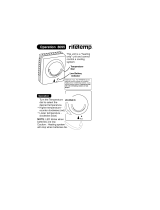
LIGHTING INSTRUCTIONS FOR HEATER WITH “SIT” GAS CONTROLS
1. STOP! Read all safety labels on the water heater before
operation.
2. Rotate the thermostat/control knob located on the gas control
clockwise to the “OFF” position.
3. Wait 5 minutes to clear out any gas. If you smell gas, STOP!
Follow instruction “B” above on this page. If you do not smell
gas, go to the next step.
4. To light heater, remove outer door and slide inner door to the
right.
5. Find pilot. Follow aluminum tube from the underside of the gas
control. The pilot is in front of the burner.
6. Turn the thermostat/control knob counterclockwise to the
“PILOT” position.
7. Use a lit match held securely with an extension device, or a
long stem igniter. While holding the ignition source at the pilot,
depress the pilot button to light the pilot.
8. Keep pilot button depressed for 60 seconds to properly heat
thermocouple and activate safety controls.
9. If pilot does not remain lit, repeat steps 7 & 8.
• If the pilot will not stay lit after several attempts, turn the
thermostat/control knob to “OFF” and contact your service
technician.
• If the pilot button does not pop up when released, stop and
immediately call your service technician or gas supplier.
10. Once the pilot is established, slide the inner door to the left
and replace the outer door.
11. Turn the thermostat control knob counterclockwise to turn
on the heater. Set the knob position to the “LOW” marking to
start. Adjust the temperature up as required.
To Turn Off the Gas Control
1. Rotate the thermostat control knob clockwise to the “OFF”
position.
SIT GAS CONTROL (TOP VIEW)

– 8 –
SPECIAL NOTE ON PROPANE FUEL:
L.P. GAS IS HEAVIER THAN AIR
Should there be a leak in the system, the gas will settle at
FLOOR LEVEL. Basements, crawl spaces, closets and areas
below ground level will serve as pockets for the accumulation of
the gas.
BEFORE LIGHTING, SNIFF AT FLOOR LEVEL. IF YOU
SMELL GAS, FOLLOW THESE RULES.
1. Get all people out of the building.
2. DO NOT light matches.
3. DO NOT touch electrical switches (on or off).
4. DO NOT use an electrical fan to remove gas from area.
5. SHUT OFF GAS at the L.P. tank outside of the building.
6. IMMEDIATELY call the L.P. Gas Company or the fire
department from a neighbor’s phone. Ask for instructions. Before
hanging up, give your name, address and telephone number.
7. DO NOT go back into the building. If help is coming, wait for
it outside the building.
OUT OF FUEL
When your L.P. tank runs out of fuel, turn off gas at all gas
appliances. After L.P. tank is refilled, all appliances must be re-lit
according to the manufacturers instructions.
LIGHTING INSTRUCTIONS FOR HEATER WITH “ROBERTSHAW R110” GAS
CONTROLS
WARNING: Should overheating occur or the gas supply fail to shut off, turn off the manual gas valve to the appliance.
LIGHTING INSTRUCTIONS FOR HEATER WITH “ROBERTSHAW 220R” GAS
CONTROLS
WARNING: Should overheating occur or the gas supply fail to shut off, turn off the manual gas valve to the appliance.
1. STOP! Read all safety labels on the water heater before operation.
2. Set the thermostat to the lowest setting. Rotate dial on front of control
counterclockwise.
3. Rotate gas control knob on top of thermostat clockwise to “OFF” position.
4. Wait 5 minutes to clear out any gas. If you smell gas, STOP! Follow
instruction “B” above on page 7. If you do not smell gas, go to the next step.
5. Remove outer door. Slide inner combustion door to right.
6. Find pilot. Follow aluminum tube from the “right-underside” of the gas
thermostat. The pilot is adjacent to burner.
7. Turn gas control knob counterclockwise to “PILOT” position.
8. Use a lit match held securely with an extension device, or a long stem igniter.
While holding the ignition source at the pilot, depress the red pilot set button
(upper left) to light the pilot. Continue to hold the pilot set button for about 1
minute after pilot is lit. Release pilot set button and it will pop up. Pilot should
remain lit.
•If knob does not pop up when released, stop and immediately call your
service technician or gas supplier.
•If the pilot will not stay lit after several tries, turn the control knob to “OFF”
and call your service technician or gas supplier.
9. Slide inner combustion door to left and replace outer door.
10. Turn gas control knob counterclockwise to “ON” position.
11. Set the thermostat to desired setting clockwise.
1. STOP! Read all safety labels on the water heater before operation.
2. Rotate gas control knob on top of thermostat clockwise to “OFF” position.
3. Set the thermostat to lowest setting.
4. Wait (5) minutes to clear out any gas. If you then smell gas, STOP! Follow
instruction “B” above on page 7. If you don’t smell gas, go to the next step.
5. Remove outer door. Slide inner combustion door to right.
6. Find pilot. Follow aluminum tube from the “right-underside” of the gas
thermostat. The pilot is adjacent to burner.
7. Turn gas control knob counterclockwise to “PILOT” position.
8. Use a lit match held securely with an extension device, or a long stem igniter.
While holding the ignition source at the pilot, depress the gas control knob to
light the pilot.
9. After pilot lights, keep knob depressed for at least 60 seconds to properly
heat thermocouple and activate safety valves.
10. If the pilot does not remain lit wait at least 10 minutes and repeat steps 1-9.
•If knob does not pop up when released, stop and immediately call your
service technician or gas supplier.
•If the pilot will not stay lit after several tries, turn the control knob to “OFF”
and call your service technician or gas supplier.
11. Slide inner combustion door to left and replace outer door.
12. Turn gas control knob counterclockwise to “ON” position.
13. Set thermostat to desired setting clockwise.
To Turn Off the Gas Control
1. Set the thermostat dial to the lowest setting. Turn
counterclockwise.
2. Turn gas control knob “OFF”. Rotate clockwise.
To Turn Off the Gas Control
1. Set the thermostat dial to the lowest setting. Turn
counterclockwise.
2. Turn gas control knob “OFF”. Rotate clockwise.
ROBERTSHAW R110 GAS CONTROL
ROBERTSHAW 220R GAS CONTROL
TEMPERATURE DIAL

– 9 –
Water Temperature Regulation
The thermostat is adjusted to its lowest temperature position when
shipped from the factory. The temperature of the water can be
selected by setting of the temperature dial on the front of the gas
control. The “LOW” position on the thermostat is the preferred
starting point for setting the temperature/control knob
(approximately 120
O
F(50
O
C)). Energy conservation is a
consideration when selecting the water temperature setting.
HIGHER SETTING INCREASES THE RISK OF SCALD
INJURY
In households with children, the elderly or handicapped persons,
select a lower temperature setting. To reduce the risk of scalding,
valves for reducing the point of discharge water temperature by
mixing the branch water lines are available. Please consult a
licensed plumbing authority.
Performance Checks
1.Burner Manifold Pressure - The burner operates at a manifold
gas pressure of 3.5” W.C. for natural gas and 10.0” W.C. for
propane gas. A
1
/8” N.P.T. port is provided on the gas valve
control for connection to a gauge to measure the pressure. The
control valve has an internal pressure regulator. Do not confuse
the manifold pressure with the supply inlet pressure. Return port
plug upon completion of tests.
2.Checking Input - Never exceed input shown on the rating plate.
Ask your gas supplier for the heating value of the gas you are
using. Check the input by ”clocking” the gas meter. Make sure
no other appliances are operating when the test is being done.
To ensure accuracy, clock enough gas so that the time is greater
than 60 seconds. Use the following formula to check input.
Check that your gas pressures are as previously stated.
3.Checking burner flame - Water Heaters may use either a sheet
metal or cast iron burner. Access the burner by lifting off the
outer gas door and sliding open the inner door located at the
bottom of the water heater.
• For water heaters having a sheet metal burner and burning
natural gas, a constant, steady, soft blue flame should be visible
coming from the burner head.
• For water heaters having a sheet metal burner and burning
propane gas, the flame will be a constant, steady blue with a
brighter blue being visible right at the burner head. The very
ends of the flame may be tipped with yellow. This is more
noticeable on higher input units.
• Noisy, hard blue flames, flames lifting from the burner, luminous
or yellow stringy flames indicate an incorrect setup. Check that
the unit is using the correct gas. This information is on the rating
plate and the label on the side of the gas valve control. Poor
flames can also be caused by incorrect gas pressures or burner
orifice size, inadequate or contaminated air, a restriction in the
venting system, or dirt entering the gas supply. These conditions
must be corrected to prevent a possible safety hazard.
• For units with cast iron burners, the flame presentation should
be the same as sheet metal burners. Adjustment is possible on
cast iron burners by changing the air shutter position on the
burner inlet. If the flame needs adjusting, loosen the two screws
and move the shutter. See Figure 8. If it is too far open, the
flame will lift off the burner or will be noisy; if it is closed too far,
the flame will be luminous and yellow. Once proper flame is
obtained, tighten the screws to secure the air shutter.
NOTE:
There is no means for flame adjustment on sheet metal
burners as they are self-adjusting.
IMPORTANT:
Always return the burner doors
to their original position.
ALWAYS KEEP THE AREA AROUND THE WATER
HEATER CLEAR OF COMBUSTIBLE MATERIALS.
NEVER RESTRICT THE FLOW OF AIR TO THE
WATER HEATER.
VII) SERVICE AND MAINTENANCE
This section describes the routine service
instructions to properly maintain your heater and
venting system.
Not Enough or No Hot Water
• Check that the water heater is operational.
• Relight the pilot burner if necessary.
• Check that the thermostat is set high enough.
• Check that you have not just run out of hot water due to heavy
demand. If this is a routine problem, it may indicate an under-
sized water heater.
• Have your gas company check input rate and water heater
operation.
• The E.C.O. may have tripped open. See E.C.O. below.
Energy Cut-off Control (E.C.O.)
This water heater is equipped with a control which has a built in
E.C.O. (Energy Cut-Off). The E.C.O. will shut the gas off, should
the outlet water temperature exceed maximum temperatures. If
the E.C.O. has tripped, the entire gas valve/temperature control
must be replaced. For gas valve/temperature control
replacement, contact your local gas utility, or a qualified service
technician. The replacement control must be an approved
equivalent model to the control which has been removed.
Water Temperature is Too Hot
• Check that thermostat setting is not too high.
• Water heaters used for dishwashers, space heating or laundry
facilities generally require higher temperatures than domestic
use. Install anti-scald tempering valves as instructed in the
safety warnings.
• If the problem persists, contact your dealer or gas supplier.
Hot Water Odour
On occasion, and depending on your location, hot water may
develop a strong odour. This can be especially problematic in
regions where the water contains some sulphur, which results in
hot water having a “rotten egg” smell.
If this occurs, drain the system completely, flush thoroughly and
refill. If the problem persists, the anode rod may need to be
changed from magnesium to one made of aluminum. In certain
cases chlorination and flushing of the water heater may be
required. Contact you dealer or water supplier.
Input Gas Heating Value* x Cubic Feet(Meters) clocked
(BTU/Hour) = Seconds clocked/3600
*Gas Heating Value in BTU/cubic feet or cubic meters
1 cubic meter = 35.31 cubic feet
GOOD BLUE
FLAMES
Figure 8

– 10 –
Discolored Water
• Water rich in iron or other minerals can produce red or brown
staining. Heating water generally worsens this situation.
• Black water can be an indication of organic contaminates in the
water supply. This can be problematic in areas where the water
is obtained from surface or contaminated sources. Organic
particles can develop bacterial growth, causing potential health
hazards. Contact your water supplier for proper filtration or water
conditioning equipment. For bacterial problems contact your
local health authority. See also “Hot Water Odour”
• A sudden appearance of rusty water can indicate the anode rod
has been depleted. The remaining steel core wire may be
corroding, releasing iron particles into the water. Inspect and
replace as necessary.
Water Heater Makes Noise
• During start up or under heavy use, condensation can drip on
the burner causing a sizzling noise as the water is evaporated.
This is normal and will stop once temperatures rise.
• Sediment, sand or scale can accumulate resulting in “rumbling”
noises. Water heaters need to be flushed regularly to minimize
buildup. Severe accumulations can cause premature failure of
the water heater and will void the warranty.
Condensation
At certain times of the year, when the incoming water is
particularly cold there will be condensation formed from the flue
gases while the burner is on. This condensation will drop down
onto the burner and make a hissing or sizzling sound. This is
normal and should not be a reason for concern. Normally, this
condensation will evaporate and be carried up the flue and
chimney to the outdoors.
Generally, the higher the efficiency of the heater and the cooler
the incoming water, the more condensation will occur. The bottom
pan of the heater has been designed to contain a certain amount
of water, but on occasion the water may be too much and
overflow. Do not confuse this with a leaking heater.
If condensation is a problem, raise the water temperature slightly
to operate the tank at a higher temperature and thus minimize
condensation.
Extended Non Use Service
Hydrogen gas can be produced by water heaters in service but on
standby for long periods of time (generally two weeks or more).
See safety warnings near the front of the manual. Hydrogen gas
is extremely flammable. Use caution in opening faucets.
Energy Conservation
The following are some simple tips that will help reduce energy
costs and provide maximum service from your water heater.
Temperature: Set temperature as low as possible to provide an
adequate supply of hot water. This will reduce heat loss and
extend the life of the glass-lining.
Water usage: Try to use less hot water by doing laundry and
dishwashing at the lowest temperature. Showers are more
economical than baths. Small amounts of dishes should be
washed by hand. Eliminate dripping faucets.
Water heater location: Locate heater close to a major point
of hot water use, e.g. laundry washer. This minimizes heat losses
from piping and gets water to appliance at maximum temperature.
Do not locate heater in cold or drafty locations.
Piping: Insulate all hot water pipes. This reduces heat loss from
pipes. Keep pipe runs as short as possible to deliver water to the
point of use quickly.
Going away?: If you are leaving for a period of time, turn the
temperature dial to the lowest setting. There is no point in heating
what is not needed.
Cathodic Protection: Anode
Maintenance
Your water heater has been supplied with one or two anode rods
that protects the tank from corrosion. As the rod works, it slowly
dissolves over time and must be replaced. If the anode is less
than 3/8”(10mm) in diameter, or any exposed bare core, replace.
Depending on water conditions, an anode can last from one to ten
years. Many localities treat their water which can have significant
effect on the life of your heater. Water conditioning such as over
softening can accelerate the rate at which the anode rod is
consumed. Rapid depletion can leave a heater unprotected
causing a premature failure. As with any water heater, it is good
practice to check the anode annually to see if it needs replacing
(See Figure 11, Item No. 3).
To inspect or change an anode:
• Turn off the water heater.
• Close the cold inlet supply valve.
• Open a hot water tap supplied by the heater.
• Drain the water heater enough to empty the piping system.
• Using a 1 1/16” socket, remove anode and inspect or replace as
required.
• Apply a good grade of pipe dope to the threads of the anode
adapter and screw securely into the tank.
• Refill system with water, check for leaks and restore water
heater to operation.
WARNING
Operating a water heater without an actively
working anode rod will void the warranty.
Tank Flushing
Periodically (monthly) drain approximately 2 gallons (8 liters) or
until water runs clear from the tank through the drain valve. This
will minimize sediment buildup on the tank bottom.
Caution: WATER WILL BE HOT.
If scale removal is being considered, contact your dealer for
proper procedures. DO NOT USE HYDROCHLORIC ACID (HCL)
based cleaners. Thoroughly flush after any chemical cleaning.
Relief Valve Check
Inspect the relief valve annually to ensure proper operation. This
involves opening the valve to check that it is flowing freely and that
there are no blockages. Warning: WATER WILL BE HOT
and water flow can be forceful. If the valve does not function
properly, it must be replaced. Provide a bucket or drainage for the
expelled water. Lift the lever and let it snap shut. The water should
stop immediately.
In systems where the relief valve discharges periodically, this may
be due to thermal expansion or to a thermostat that is operating at
too high a temperature. In a closed water system, an expansion
tank may be required. Contact your local plumbing inspector. For
a malfunctioning thermostat, contact your gas supplier.
Vent Maintenance
Every 6 months, when inspecting the burner flame, an inspection
of the venting system should be made.
Check these points:
1. Are the draft hood relief openings free of obstruction?
2. Is the flue pipe securely attached?
3. Is the flue pipe cemented into the chimney or are cracks and
loose cement visible?
4. Are the flue gases venting properly?
CORRECT ANY DEFECTS IMMEDIATELY!
Burner Maintenance
Annually inspect the burner and combustion chamber area to
ensure that no debris have fallen on the burner and that no foreign
material has found its way into the combustion chamber. Observe
the flame for proper operation. Sheet metal burners have no
adjustment, so contact your gas supplier if there is a problem.
ALWAYS KEEP THE AREA AROUND THE WATER HEATER
CLEAR OF COMBUSTIBLE MATERIALS. NEVER RESTRICT
THE FLOW OF AIR TO THE WATER HEATER.

– 11 –
VIII) HEATING AND SPACE HEATING
(COMBO HEATING)
This section serves as a guide for the installation and use of
“Combo” heating systems utilizing a domestic water heater which
has been specifically approved for such use. It is written for those
knowledgeable in the required trades and professionals involved
in the design and installation of Combo Heating Systems.
It is the responsibility of the installer/ designer to
follow all applicable codes to ensure the
effectiveness and safety of the installation.
Caution
READ BEFORE PROCEEDING
The following requirements must be met for the installation of
Combo Heating Systems:
1.All components used for the distribution of water in the heating
loop must be suitable for potable water. These include all piping,
fittings, solder and fluxes, pumps for circulation of water, valves,
etc.
2.The water heater must not be connected to a hydronic
heating system that has been used previously.
3.No boiler treatment chemicals of any kind shall be introduced
into the system.
4.The Combo System components must be selected and sized to
meet and maintain the total calculated demands for both domestic
service hot water and space heating requirement. The sizing and
installation must be performed in accordance with good
engineering practice such as ASHRAE Handbooks, HRAI,
Hydronics Institute Manuals, CGA B149, NFPA 54, ANSI Z223.1,
CSA F280, National/Provincial Building Codes, CSA C22.1,
ANSI/NFPA 70, CSA B51 and/or codes having jurisdiction.
5.The air handler (fan coil) and/or the circulating pump in a
baseboard hydronic loop will require a dedicated 120V circuit.
This must be provided and identified for this purpose.
6.All piping between the water heater and the air handler or
hydronic baseboard loop must be adequately insulated to reduce
heat loss.
7.If the local jurisdiction requires a back-flow preventer in the cold
water line, an expansion tank of adequate size must be installed.
8.To reduce the scald hazard potential, a mixing valve must be
installed.
INSTALLATION
The heating mode may be one of the following options:
A- A fan coil/air handler (figure 9).
B- A hydronic baseboard (finned tube) loop/ In floor heating (figure
10).
The following is a list of requirements for the installation of the
heating loop to the water heater.
a)Install shut-off valves and unions so that the water heater can
be isolated from the heating module should servicing of the water
heater become necessary.
b)Install a drain valve at the lowest point of the heating loop so
that water can be drained from the heating module without
affecting the water heater.
c)If the air handler does not have a venting means at the highest
point of the piping arrangement, install an air bleed at the highest
point of the plumbing arrangement.
MAINTENANCE
The installation and maintenance of the water heater must follow
all of the instructions described in sections I to VII of this manual.
Heater failure that is a result of the heating system is not covered
by warranty.
Figure 9
Figure 10

– 12 –
INSTALLATION RECORD
This water heater is protected by a multi-year warranty against leaks plus a one (1) year warranty on parts.
Record key data here for future reference and prompt service:
Installed By/ Purchased From: Installation Date:
Location of Gas Shut Off Valve:
Catalogue Number Model Number Serial Number
Btu Fuel Type P.S.I. U.S. Gal.
IF YOU HAVE ANY INSTALLATION, PERFORMANCE OR OPERATIONAL QUESTIONS PLEASE CALL THE
FOLLOWING NUMBER, PRIOR TO REMOVING THE WATER HEATER
(if this is a rental water heater please contact the rental company)
1-888-GSW-TECH
1-888-479-8324
FOR ASSISTANCE OR ADDITIONAL INFORMATION, CONSULT A QUALIFIED INSTALLER, SERVICE
AGENCY, OR THE GAS UTILITY.
Figure 11
IX) REPLACEMENT PARTS LISTING

See Rating Label Serial Number prefix for
Warranty Code. Reduced warranty period
applies to Newfoundland.
Warranty Code: P R S T U V W Y
Standard Warranty Years: 3 5 6 7 8 9 10 12
Reduced Warranty Years: 2 3 3 5 5 5 5 7
~ Certificate of Warranty ~
For its GSW and John Wood water heaters and storage boosters ("Unit"), GSW Water Heating ("GSW") warrants that, upon
receipt of a properly verified Warranty claim within the Warranty Period, it will, at its election, repair or replace: units which leak or parts which are defective
in material or workmanship, subject to the terms and conditions set forth in this certificate. GSW will not assume any expense or liability for unauthorized
returns, nor repairs made by a person who has not been authorized by GSW or one of its authorized dealers. GSW Units/parts must be replaced with GSW or
John Wood products to be eligible for Warranty. This Warranty is available to the original owner of a Unit installed within the boundaries of continental United
States, of Canada, or their territories. Consumers must retain point-of-sale proof of purchase to validate warranty entitlement. This Warranty does not
cover components not manufactured by GSW, such as oil burners, which carry the warranty given by the manufacturer thereof, copy of which warranty GSW
will make available, to the extent supplied by the manufacturer, without recourse to GSW.
THERE ARE NO WARRANTIES WHICH EXTEND BEYOND THE DESCRIPTION ON THE FACE HEREOF. THIS EXPRESS
WARRANTY IS, WHERE PERMITTED BY LAW, IN LIEU OF AND EXCLUDES AND REPLACES ALL OTHER CONDITIONS,
WARRANTIES, GUARANTEES, REPRESENTATIONS, OBLIGATIONS OR LIABILITIES OF GSW OF ANY NATURE OR KIND,
EXPRESS OR IMPLIED, HOWEVER ARISING (WHETHER BY CONTRACT, CONDUCT, STATEMENT, STATUTE,
NEGLIGENCE, PRINCIPLES OF MANUFACTURER'S LIABILITY, OPERATION OF LAW OR OTHERWISE) WITH RESPECT
TO THE UNIT OR ITS FITNESS FOR A PARTICULAR PURPOSE, MERCHANTABILITY, INSTALLATION, OPERATION,
REPAIR OR REPLACEMENT. GSW EXPRESSLY DISCLAIMS ANY AND ALL IMPLIED WARRANTIES. IN NO EVENT WILL
GSW'S LIABILITIES EXCEED THE COST OF THE DEFECTIVE PART(S) OR UNIT. GSW WILL NOT PAY FOR ANY
TRANSPORTATION, LABOUR, INSTALLATION, OR OTHER INCIDENTAL COSTS ASSOCIATED WITH THE REPAIR OR
REPLACEMENT OF A DEFECTIVE PART OR UNIT.
This warranty and GSW's obligations shall be construed and determined in accordance with the laws of both the Province of Ontario, and of Canada in force
therein. This Warranty does not affect specific legal rights of a consumer under applicable law, except to the extent that such rights may be waived or replaced,
and the provisions hereof are deemed to be amended to the extent necessary. The unenforceability of any provision, in whole or in part, of this Certificate shall
not affect the remaining provisions. Any and all repair and/or replacement of part(s) or Unit are the sole and exclusive remedy available against GSW.
1. The Unit shall be installed in accordance with all manufacturers'
instructions, all applicable equipment and building codes, ordinances and
regulations (hereinafter referred to as the "standards").
2. The Unit must not be installed where water damage can result from a
leak, while provision(s) shall be made for directing any water escaping
from the Unit, to a properly operating drainpipe. As all units of this type
may eventually leak, you must protect against any potential water
damage. GSW accepts no responsibility for such damage, nor any
incidental or consequential loss, nor damage(s) related thereto, suffered
by the owner of the Unit nor by any third party.
3. The Unit shall not be installed where it will be exposed to adverse or
unusual environmental or corrosive conditions. No warranty extends, for
example, and without limitation of the foregoing, to Units exposed to:
salts; chemicals; exhausts; pollutants or contaminants. Further, no
warranty extends to Units affected by fire, freezing or flood, "Acts of
God", or any other contingency beyond the control of GSW.
4. The Unit shall be equipped with a properly operating temperature and
pressure relief valve as specified by GSW and applicable standards. The
Unit shall be operated at temperatures not exceeding the maximum
setting of the thermostat and/or high limit control provided by GSW, and
at water pressures not exceeding the pressure reading stated on the Unit.
5. The Unit must be carefully inspected, maintained, and operated in
accordance with the manufacturer's instructions. No warranty extends,
for example, and without limitation of the foregoing, to any Unit
operated: without the tank being completely filled with water; without an
operating anode; with levels of sediment or lime precipitate which cause
failure; in connection to any attachment(s), energy saving device(s), or
other means of heating, except as approved by GSW for the Unit; other
than with potable water without any additives such as salts, chlorine or
chemicals, except those added for the sole purpose of rendering the water
fit for domestic use.
6. All repairs must be made by a competent and qualified person who is
certified, by GSW or one of its authorized dealers, to work on the Unit,
using factory approved replacement parts, and the Unit shall not be
otherwise modified, altered or improperly repaired.
7. A properly documented claim shall be received by GSW or one of its
authorized dealers, or point of purchase, within the following Warranty
Period, except as provided otherwise below*:
a) for any defective part, within one (1) year; or
b) for any Unit that develops leaks in the inner tank due to rust, corrosion
or other chemical reactions caused by the potable domestic water
supplied to your home, within the period of time shown in table at the top
of this page.
* Residential units installed and used in a commercial application carry a
warranty period of one (1) year from date of installation; and,
Any repair or replacement of any part, tank, or Unit under this Warranty
will not extend the Warranty Period beyond that calculated from the date
of first installation of the original Unit. The date of first installation will
be deemed to be the later of the date indicated by the Unit's serial number,
or if supplied with the Warranty claim, the sales receipt, or installer's
receipt.
8. A claim under this Warranty must include the model and serial number of
the Unit, proof of date on which the Unit was first installed, and the
identity of the defective part(s) for which a claim is being made and be
submitted within 15 days following discovery of the defect(s), by
personal delivery to a GSW authorized dealer, point of purchase, or GSW
itself at:
GSW Water Heating
A GSW Company
599 Hill Street West
Fergus, ON Canada N1M 2X1
Should you have questions, please call our Technical Support Line at 1-
888-479-8324.
9. If requested by GSW, information relating to the purchase, transportation,
operation and installation of the Unit must be supplied. The defective
part(s) or Unit, with all components properly and securely packed, shall
be returned transportation pre-paid, to the address designated by GSW in
the written request. All claims are subject to validation by GSW.
LIABILITY OF GSW COVERED BY THIS WARRANTY IS CONDITIONAL UPON THE FOLLOWING:
– 13 –
/