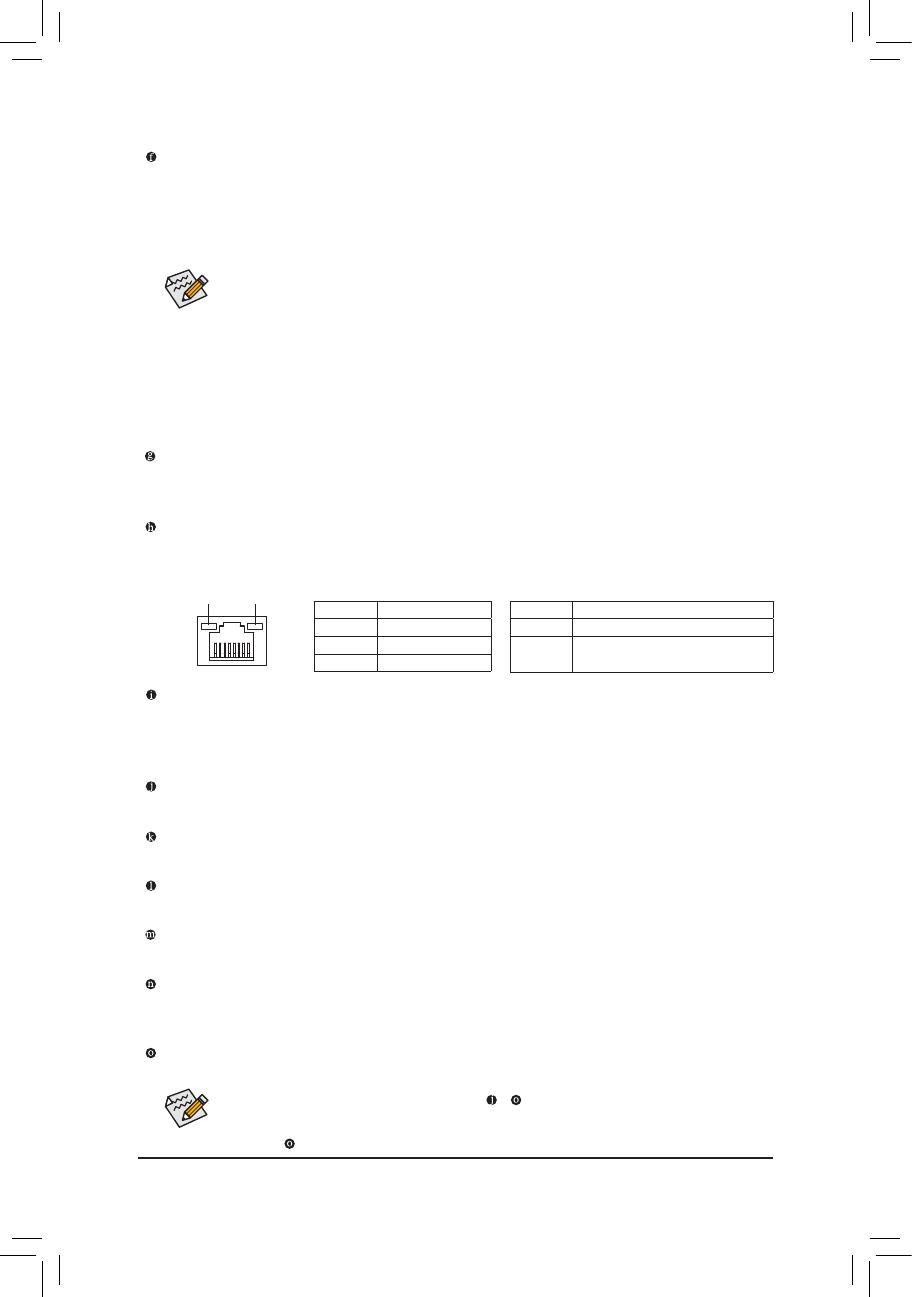
Gigabyte GA-Q77M-D2H User manual

Category
Motherboards
Type
User manual
GA-Q77M-D2H
User's Manual
Rev. 1001
12ME-Q77MD2H-1001R
Motherboard
GA-Q77M-D2H
Apr. 18, 2012
Apr. 18, 2012
Motherboard
GA-Q77M-D2H
Copyright
© 2012 GIGA-BYTE TECHNOLOGY CO., LTD. All rights reserved.
The trademarks mentioned in this manual are legally registered to their respective owners.
Disclaimer
Information in this manual is protected by copyright laws and is the property of GIGABYTE.
Changes to the specications and features in this manual may be made by GIGABYTE without
prior notice. No part of this manual may be reproduced, copied, translated, transmitted, or
published in any form or by any means without GIGABYTE's prior written permission.
In order to assist in the use of this product, carefully read the User's Manual.
For product-related information, check on our website at: http://www.gigabyte.com
Identifying Your Motherboard Revision
The revision number on your motherboard looks like this: "REV: X.X." For example, "REV:
1.0" means the revision of the motherboard is 1.0. Check your motherboard revision before
updating motherboard BIOS, drivers, or when looking for technical information.
Example:
- 4 -
Table of Contents
GA-Q77M-D2H Motherboard Layout ............................................................................... 5
GA-Q77M-D2H Motherboard Block Diagram ..................................................................6
Chapter 1 Hardware Installation .....................................................................................7
1-1 Installation Precautions .................................................................................... 7
1-2 ProductSpecications ...................................................................................... 8
1-3 Installing the CPU .......................................................................................... 11
1-4 Installing the Memory ..................................................................................... 12
1-5 Installing an Expansion Card ......................................................................... 12
1-6 Back Panel Connectors .................................................................................. 13
1-7 Internal Connectors ........................................................................................ 15
Chapter 2 BIOS Setup ..................................................................................................24
2-1 Startup Screen ............................................................................................... 24
2-2 The Main Menu .............................................................................................. 25
2-3 M.I.T. .............................................................................................................. 26
2-4 System ........................................................................................................... 33
2-5 BIOS Features ............................................................................................... 34
2-6 Peripherals ..................................................................................................... 36
2-7 Power Management ....................................................................................... 42
2-8 Save & Exit ..................................................................................................... 44
Chapter 3 Drivers Installation ........................................................................................45
3-1 Installing Chipset Drivers ............................................................................... 45
3-2 Regulatory Statements ................................................................................... 46
- 5 -
GA-Q77M-D2H Motherboard Layout
KB_MS
CPU_FAN
SYS_FAN
LGA1155
ATX
GA-Q77M-D2H
F_AUDIO
AUDIO
BIOS
DDR3_4
DDR3_3
DDR3_2
DDR3_1
F_PANEL
ATX_12V
Intel
®
Q77
SATA2
2 3
4 5
SATA3
0 1
F_USB30
USB30_LAN
CODEC
CLR_CMOS
VGA_DVI
PCIEX16
PCIEX1
PCI
PCIEX4
SPDIF_O
F_USB2
F_USB1
LPT
COMB
DP_HDMI_SPDIF
Intel GbE
LAN
iTE
Super I/O
R_USB
DEBUG_PORT
COMA
BAT
Box Contents
GA-Q77M-D2H motherboard
Motherboard driver disk Two SATA cables
User's Manual I/O Shield
The box contents above are for reference only and the actual items shall depend on the product package you obtain.
The box contents are subject to change without notice.
TPM IC
(Note)
(Note) This feature is optional due to different regional policy.
- 6 -
GA-Q77M-D2H Motherboard Block Diagram
PS/2 KB/Mouse
LPT
LPC
Bus
LGA1155
CPU
PCI Express Bus
CPU CLK+/- (100 MHz)
PCIe CLK
(100 MHz)
1 PCI Express x16
x16
DMI 2.0
FDI
DDR3 1600/1333/1066 MHz
Dual Channel Memory
LAN
RJ45
PCI Express Bus
PCIe CLK
(100 MHz)
Intel
GbE LAN
1 PCI Express x1
1 PCI Express x4
1 PCI
x1 x4
x1
BIOS
D-Sub
DVI-D
2 SATA 6Gb/s
4 USB 3.0/2.0
4 SATA 3Gb/s
8 USB 2.0/1.1
Intel
®
Q77
iTE
Super
I/O
Fordetailedproductinformation/limitation(s),referto"1-2ProductSpecications."
COM Ports
Center/Subwoofer Speaker Out
Line Out
MIC
Line In
S/PDIF Out
Side Speaker Out
Surround Speaker Out
CODEC
DisplayPort
HDMI
TPM
- 7 -
Chapter 1 Hardware Installation
1-1 Installation Precautions
The motherboard contains numerous delicate electronic circuits and components which can become
damaged as a result of electrostatic discharge (ESD). Prior to installation, carefully read the user's
manual and follow these procedures:
Prior to installation, make sure the chassis is suitable for the motherboard.
Prior to installation, do not remove or break motherboard S/N (Serial Number) sticker or
warranty sticker provided by your dealer. These stickers are required for warranty validation.
Always remove the AC power by unplugging the power cord from the power outlet before
installing or removing the motherboard or other hardware components.
When connecting hardware components to the internal connectors on the motherboard, make
sure they are connected tightly and securely.
When handling the motherboard, avoid touching any metal leads or connectors.
It is best to wear an electrostatic discharge (ESD) wrist strap when handling electronic
components such as a motherboard, CPU or memory. If you do not have an ESD wrist strap,
keepyourhandsdryandrsttouchametalobjecttoeliminatestaticelectricity.
Prior to installing the motherboard, please have it on top of an antistatic pad or within an
electrostatic shielding container.
Before unplugging the power supply cable from the motherboard, make sure the power supply
has been turned off.
Before turning on the power, make sure the power supply voltage has been set according to
the local voltage standard.
Before using the product, please verify that all cables and power connectors of your hardware
components are connected.
To prevent damage to the motherboard, do not allow screws to come in contact with the
motherboard circuit or its components.
Make sure there are no leftover screws or metal components placed on the motherboard or
within the computer casing.
Do not place the computer system on an uneven surface.
Do not place the computer system in a high-temperature environment.
Turning on the computer power during the installation process can lead to damage to system
components as well as physical harm to the user.
If you are uncertain about any installation steps or have a problem related to the use of the
product,pleaseconsultacertiedcomputertechnician.
- 8 -
1-2 ProductSpecications
CPU Support for Intel
®
Core
i7 processors/Intel
®
Core
i5 processors/
Intel
®
Core™ i3 processors/Intel
®
Pentium
®
processors/In-
tel
®
Celeron
®
processors in the LGA1155 package
(Go to GIGABYTE's website for the latest CPU support list.)
L3 cache varies with CPU
Chipset Intel
®
Q77 Express Chipset
Memory 4 x 1.5V DDR3 DIMM sockets supporting up to 32 GB of system memory
* Due to Windows 32-bit operating system limitation, when more than 4 GB of physical
memory is installed, the actual memory size displayed will be less than 4 GB.
Dual channel memory architecture
Support for DDR3 1600/1333/1066 MHz memory modules
Support for non-ECC memory modules
(Go to GIGABYTE's website for the latest supported memory speeds and memory
modules.)
Onboard
Graphics
Integrated Graphics Processor:
- 1 x D-Sub port
- 1 x DVI-D port, supporting a maximum resolution of 1920x1200
* The DVI-D port does not support D-Sub connection by adapter.
- 1 x HDMI port, supporting a maximum resolution of 1920x1200
- 1 x DisplayPort, supporting a maximum resolution of 2560x1600
Audio Realtek ALC887 codec
High Denition Audio
2/4/5.1/7.1-channel
Support for S/PDIF Out
LAN 1 x Intel GbE LAN chip (10/100/1000 Mbit)
Expansion Slots 1 x PCI Express x16 slot, running at x16 (PCIEX16)
(The PCIEX16 slot conforms to PCI Express 3.0 standard.)
* For optimum performance, if only one PCI Express graphics card is to be installed,
be sure to install it in the PCIEX16 slot.
* The PCI Express x16 slots support up to PCI Express 3.0 standard when an Intel
22nm (Ivy Bridge) CPU is installed.
1 x PCI Express x16 slot, running at x4 (PCIEX4)
1 x PCI Express x1 slot
(The PCIEX4 and PCIEX1 slots conform to PCI Express 2.0 standard.)
1 x PCI slot
Multi-Graphics
Technology
Support for AMD CrossFireX™ technology
* The PCIEX16 slot operates at up to x4 mode when AMD CrossFireX™ is enabled.
- 9 -
Storage Interface Chipset:
- 2 x SATA 6Gb/s connectors (SATA3 0/1) supporting up to 2 SATA 6Gb/s
devices
- 4 x SATA 3Gb/s connectors (SATA2 2/3/4/5) supporting up to 4 SATA 3Gb/s
devices
- Support for RAID 0, RAID 1, RAID 5, and RAID 10
* When a RAID set is built across the SATA 6Gb/s and SATA 3Gb/s channels, the
system performance of the RAID set may vary depending on the devices being
connected.
USB Chipset:
- Up to 8 USB 2.0/1.1 ports (4 ports on the back panel, 4 ports available
through the internal USB headers)
- Up to 4 USB 3.0/2.0 ports (2 ports on the back panel, 2 ports available through
the internal USB header)
* In Windows XP, the Intel USB 3.0 ports can support up to USB 2.0 transfer speed.
Internal
Connectors
1 x 24-pin ATX main power connector
1 x 4-pin ATX 12V power connector
2 x SATA 6Gb/s connectors
4 x SATA 3Gb/s connectors
1 x CPU fan header
1 x system fan header
1 x front panel header
1 x front panel audio header
1 x S/PDIF Out header
1 x USB 3.0/2.0 header
2 x USB 2.0/1.1 headers
2 x serial port headers
1 x parallel port
1 x debug card header
1 x Clear CMOS jumper
Back Panel
Connectors
1 x PS/2 Keyboard port
1 x PS/2 mouse port
1 x D-Sub port
1 x DVI-D port
1 x optical S/PDIF Out connector
1 x HDMI port
1 x DisplayPort
2 x USB 3.0/2.0 ports
4 x USB 2.0/1.1 ports
1 x RJ-45 port
6 x audio jacks (Center/Subwoofer Speaker Out/Rear Speaker Out/Side Speaker
Out/Line In/Line Out/Microphone)
I/O Controller iTE I/O Controller Chip
- 10 -
Hardware
Monitor
System voltage detection
CPU/System temperature detection
CPU/System fan speed detection
CPU overheating warning
CPU/System fan fail warning
CPU/System fan speed control
* Whether the CPU/system fan speed control function is supported will depend on the
CPU/system cooler you install.
BIOS 1 x 64 Mbit ash
Use of licensed AMI EFI BIOS
PnP 1.0a, DMI 2.0, SM BIOS 2.6, ACPI 2.0a
Unique Features Support for @BIOS
Support for Xpress Install
Support for Xpress Recovery2
Support for eXtreme Hard Drive (X.H.D)
Support for Auto Green
Support for ON/OFF Charge
Support for Q-Share
Support for EZ Setup
Support for Smart TPM
* This feature is optional due to different regional policy.
Bundled
Software
Norton Internet Security (OEM version)
Intel
®
Rapid Start Technology
Intel
®
Smart Connect Technology
Intel
®
Smart Response Technology
Operating
System
Support for Microsoft
®
Windows 7/XP
Form Factor Micro ATX Form Factor; 24.4cm x 24.4cm
* GIGABYTE reserves the right to make any changes to the product specications
and product-related information without prior notice.
- 11 -
1-3 Installing the CPU
Installing the CPU
Locate the alignment keys on the motherboard CPU socket and the notches on the CPU.
Notch
Alignment
Key
Alignment
Key
Notch
LGA1155 CPU
LGA1155 CPU Socket
Pin One Corner of the CPU Socket
Triangle Pin One Marking on the CPU
Read the following guidelines before you begin to install the CPU:
Make sure that the motherboard supports the CPU.
(Go to GIGABYTE's website for the latest CPU support list.)
Always turn off the computer and unplug the power cord from the power outlet before installing the
CPU to prevent hardware damage.
Locate the pin one of the CPU. The CPU cannot be inserted if oriented incorrectly. (Or you may
locate the notches on both sides of the CPU and alignment keys on the CPU socket.)
Apply an even and thin layer of thermal grease on the surface of the CPU.
Do not turn on the computer if the CPU cooler is not installed, otherwise overheating and damage
of the CPU may occur.
SettheCPUhostfrequencyinaccordancewiththeCPUspecications.Itisnotrecommended
thatthesystembusfrequencybesetbeyondhardwarespecicationssinceitdoesnotmeetthe
standard requirements for the peripherals. If you wish to set the frequency beyond the standard
specications,pleasedosoaccordingtoyourhardwarespecicationsincludingtheCPU,graphics
card, memory, hard drive, etc.
- 12 -
1-4 Installing the Memory
DDR3_4
DDR3_2
DDR3_3
DDR3_1
Due to CPU limitations, read the following guidelines before installing the memory in Dual Channel mode.
1. Dual Channel mode cannot be enabled if only one DDR3 memory module is installed.
2. When enabling Dual Channel mode with two or four memory modules, it is recommended that memory
of the same capacity, brand, speed, and chips be used and installed in the same colored DDR3
sockets. For optimum performance, when enabling Dual Channel mode with two memory modules,
we recommend that you install them in the DDR3_1 and DDR3_2 sockets.
(SS=Single-Sided, DS=Double-Sided, "- -"=No Memory)
DualChannelMemoryCongurationsTable
DDR3_4 DDR3_2 DDR3_3 DDR3_1
Two Modules - - DS/SS - - DS/SS
DS/SS - - DS/SS - -
Four Modules DS/SS DS/SS DS/SS DS/SS
Read the following guidelines before you begin to install the memory:
Make sure that the motherboard supports the memory. It is recommended that memory of the same
capacity, brand, speed, and chips be used.
(Go to GIGABYTE's website for the latest supported memory speeds and memory modules.)
Always turn off the computer and unplug the power cord from the power outlet before installing the
memory to prevent hardware damage.
Memory modules have a foolproof design. A memory module can be installed in only one direction.
If you are unable to insert the memory, switch the direction.
DualChannelMemoryConguration
This motherboard provides four DDR3 memory sockets and supports Dual Channel Technology. After the
memoryisinstalled,theBIOSwillautomaticallydetectthespecicationsandcapacityofthememory.Enabling
Dual Channel memory mode will double the original memory bandwidth.
The four DDR3 memory sockets are divided into two channels and each channel has two memory sockets as
following:
Channel A: DDR3_1, DDR3_3
Channel B: DDR3_2, DDR3_4
1-5 Installing an Expansion Card
Read the following guidelines before you begin to install an expansion card:
Make sure the motherboard supports the expansion card. Carefully read the manual that came
with your expansion card.
Always turn off the computer and unplug the power cord from the power outlet before installing an
expansion card to prevent hardware damage.
- 13 -
1-6 Back Panel Connectors
(Note) The DVI-D port does not support D-Sub connection by adapter.
After installing the HDMI device, make sure to set the default sound playback device to HDMI.
(The item name may differ depending on your operating system. The screenshot below is from
Windows 7.)
In Windows 7, select Start>Control Panel>Hardware and
Sound>Sound>Playback, set Intel(R) Display Audio to the
default playback device.
Whenremovingthecableconnectedtoabackpanelconnector,rstremovethecablefromyour
device and then remove it from the motherboard.
When removing the cable, pull it straight out from the connector. Do not rock it side to side to prevent
an electrical short inside the cable connector.
PS/2 Keyboard and PS/2 Mouse Port
Use the upper port (green) to connect a PS/2 mouse and the lower port (purple) to connect a PS/2 keyboard.
D-Sub Port
The D-Sub port supports a 15-pin D-Sub connector. Connect a monitor that supports D-Sub connection
to this port.
DVI-D Port
(Note)
TheDVI-DportconformstotheDVI-Dspecicationandsupportsamaximumresolutionof1920x1200
(the actual resolutions supported depend on the monitor being used). Connect a monitor that supports
DVI-D connection to this port.
Optical S/PDIF Out Connector
This connector provides digital audio out to an external audio system that supports digital optical audio.
Before using this feature, ensure that your audio system provides an optical digital audio in connector.
HDMI Port
The HDMI port is HDCP compliant and supports Dolby True HD and DTS HD
Master Audio formats. It also supports up to 192KHz/24bit 8-channel LPCM audio
output. You can use this port to connect your HDMI-supported monitor. The maximum supported resolution
is 1920x1200, but the actual resolutions supported are dependent on the monitor being used.
- 14 -
Activity LED
Connection/
Speed LED
LAN Port
Activity LED:Connection/Speed LED:
State Description
Orange 1 Gbps data rate
Green 100 Mbps data rate
Off 10 Mbps data rate
State Description
Blinking Data transmission or receiving is occurring
Off No data t ransmission or rece i v i n g is
occurring
DisplayPort
DisplayPort is one of the new generation interface technologies that delivers high quality digital imaging
and audio, supporting bi-directional audio transmition. DisplayPort can support both DPCP and HDCP
content protection mechanisms. Connect the audio/video device that supports DisplayPort to this port.
The DisplayPort Technology can support a maximum resolution of 2560x1600 but the actual resolutions
supported depend on the monitor being used.
After installing the DisplayPort device, make sure the default device for sound playback is the
DisplayPort device. (The item name may differ from operating system. For example, in Windows 7,
go to Start>Control Panel>Hardware and Sound>Sound>Playback and set the DisplayPort device
as the default playback device. Refer to the HDMI settings information on the previous page for
thecongurationdialogbox.)
DualDisplayCongurationsfortheOnboardGraphics:
This motherboard provides four video output ports: D-Sub, DVI-D, HDMI, and DisplayPort. Dual monitor
confgurations are supported in operating system environment only, but not during the BIOS Setup or
POST process.
USB 2.0/1.1 Port
TheUSBportsupports the USB 2.0/1.1specication.Usethisportfor USB devices suchasaUSB
keyboard/mouse,USBprinter,USBashdriveandetc.
RJ-45 LAN Port
The Gigabit Ethernet LAN port provides Internet connection at up to 1 Gbps data rate. The following
describes the states of the LAN port LEDs.
USB 3.0/2.0 Port
TheUSB3.0portsupportstheUSB3.0specicationandiscompatibletotheUSB2.0/1.1specication.
Use this port for USB devices Use this port for USB devices such as a USB keyboard/mouse, USB printer,
USBashdriveandetc.
Center/Subwoofer Speaker Out Jack (Orange)
Usethisaudiojacktoconnectcenter/subwooferspeakersina5.1/7.1-channelaudioconguration.
Rear Speaker Out Jack (Black)
Thisjackcanbeusedtoconnectfrontspeakersina4/5.1/7.1-channelaudioconguration.
Side Speaker Out Jack (Gray)
Usethisaudiojacktoconnectsidespeakersina7.1-channelaudioconguration.
Line In Jack (Blue)
The default line in jack. Use this audio jack for line in devices such as an optical drive, walkman, etc.
Line Out Jack (Green)
The default line out jack. Use this audio jack for a headphone or 2-channel speaker. This jack can be used
toconnectfrontspeakersina4/5.1/7.1-channelaudioconguration.
Mic In Jack (Pink)
The default Mic in jack. Microphones must be connected to this jack.
In addition to the default speakers settings, the ~ audiojackscanbereconguredtoperform
different functions via the audio software. Only microphones still MUST be connected to the default
Mic in jack ( ).
- 15 -
1-7 Internal Connectors
Read the following guidelines before connecting external devices:
First make sure your devices are compliant with the connectors you wish to connect.
Before installing the devices, be sure to turn off the devices and your computer. Unplug the power
cord from the power outlet to prevent damage to the devices.
After installing the device and before turning on the computer, make sure the device cable has
been securely attached to the connector on the motherboard.
1) ATX_12V
2) ATX
3) CPU_FAN
4) SYS_FAN
5) BAT
6) SATA3 0/1
7) SATA2 2/3/4/5
8) F_PANEL
9) F_AUDIO
10) SPDIF_O
11) F_USB30
12) F_USB1/2
13) COMA/COMB
14) LPT
15) DEBUG_PORT
16) CLR_CMOS
1
14
2
11
6
9
8
7
16 1312
15
10
5
4
3
- 16 -
DEBUG
PORT
G.QBOFM
131
2412
ATX
ATX_12V:
1/2) ATX_12V/ATX (2x2 12V Power Connector and 2x12 Main Power Connector)
With the use of the power connector, the power supply can supply enough stable power to all the components
onthemotherboard.Beforeconnectingthepowerconnector,rstmakesurethepowersupplyisturned
off and all devices are properly installed. The power connector possesses a foolproof design. Connect the
power supply cable to the power connector in the correct orientation.
The 12V power connector mainly supplies power to the CPU. If the 12V power connector is not connected,
the computer will not start.
To meet expansion requirements, it is recommended that a power supply that can withstand high
power consumption be used (500W or greater). If a power supply is used that does not provide the
required power, the result can lead to an unstable or unbootable system.
Pin No. Denition
1 GND
2 GND
3 +12V
4 +12V
ATX_12V
2
1
4
3
ATX:
Pin No. Denition Pin No. Denition
1 3.3V 13 3.3V
2 3.3V 14 -12V
3 GND 15 GND
4 +5V 16 PS_ON (soft On/Off)
5 GND 17 GND
6 +5V 18 GND
7 GND 19 GND
8 Power Good 20 -5V
9 5VSB (stand by +5V) 21 +5V
10 +12V 22 +5V
11 +12V (Only for 2x12-pin
ATX)
23 +5V (Only for 2x12-pin ATX)
12 3.3V (Only for 2x12-pin
ATX)
24 GND (Only for 2x12-pin
ATX)
- 17 -
3/4) CPU_FAN/SYS_FAN (Fan Headers)
All fan headers on this motherboard are 4-pin. Most fan headers possess a foolproof insertion design.
When connecting a fan cable, be sure to connect it in the correct orientation (the black connector wire is
the ground wire). The speed control function requires the use of a fan with fan speed control design. For
optimum heat dissipation, it is recommended that a system fan be installed inside the chassis.
Be sure to connect fan cables to the fan headers to prevent your CPU and system from
overheating. Overheating may result in damage to the CPU or the system may hang.
Thesefanheadersarenotcongurationjumperblocks.Donotplaceajumpercapontheheaders.
CPU_FAN
SYS_FAN
DEBUG
PORT
G.QBOFM
DEBUG
PORT
G.QBOFM
1
1
CPU_FAN:
Pin No. Denition
1 GND
2 +12V
3 Sense
4 Speed Control
SYS_FAN:
Pin No. Denition
1 GND
2 Speed Control
3 Sense
4 Reserve
5) BAT (Battery)
Thebatteryprovidespowertokeepthevalues(suchasBIOScongurations,date,andtimeinformation)
in the CMOS when the computer is turned off. Replace the battery when the battery voltage drops to a low
level, or the CMOS values may not be accurate or may be lost.
You may clear the CMOS values by removing the battery:
1. Turn off your computer and unplug the power cord.
2. Gently remove the battery from the battery holder and wait for one minute.
(Or use a metal object like a screwdriver to touch the positive and negative
terminals of the battery holder, making them short for 5 seconds.)
3. Replace the battery.
4. Plug in the power cord and restart your computer.
Always turn off your computer and unplug the power cord before replacing the battery.
Replace the battery with an equivalent one. Danger of explosion if the battery is replaced with
an incorrect model.
Contact the place of purchase or local dealer if you are not able to replace the battery by yourself
or uncertain about the battery model.
When installing the battery, note the orientation of the positive side (+) and the negative side (-)
of the battery (the positive side should face up).
Used batteries must be handled in accordance with local environmental regulations.
- 18 -
7) SATA2 2/3/4/5 (SATA 3Gb/s Connectors, Controlled by Intel Q77 Chipset)
The SATA connectors conform to SATA 3Gb/s standard and are compatible with SATA 1.5Gb/s standard.
Each SATA connector supports a single SATA device. The Intel Q77 Chipset supports RAID 0, RAID 1,
RAID 5, and RAID 10.
ARAID0orRAID1congurationrequiresatleasttwoharddrives.Ifmorethantwoharddrives
are to be used, the total number of hard drives must be an even number.
ARAID5congurationrequiresatleastthreeharddrives.(Thetotalnumberofharddrivesdoes
not have to be an even number.)
ARAID10congurationrequiresfourharddrives.
6) SATA3 0/1 (SATA 6Gb/s Connectors, Controlled by Intel Q77 Chipset)
The SATA connectors conform to SATA 6Gb/s standard and are compatible with SATA 3Gb/s and SATA
1.5Gb/s standard. Each SATA connector supports a single SATA device. The "SATA3 0" and "SATA3 1"
connectors support RAID 0 and RAID 1. RAID 5 and RAID 10 can be implemented on the two connectors
with the "SATA2 2/3/4/5" connectors
(Note)
.
(Note) When a RAID set is built across the SATA 6Gb/s and SATA 3Gb/s channels, the system performance
of the RAID set may vary depending on the devices being connected.
7
1
Pin No. Denition
1 GND
2 TXP
3 TXN
4 GND
5 RXN
6 RXP
7 GND
Pin No. Denition
1 GND
2 TXP
3 TXN
4 GND
5 RXN
6 RXP
7 GND
SATA3
0 1
7
7
1
1
DEBUG
PORT
G.QBOFM
DEBUG
PORT
G.QBOFM
DEBUG
PORT
G.QBOFM
DEBUG
PORT
G.QBOFM
SATA2
2 3
4 5
DEBUG
PORT
G.QBOFM
DEBUG
PORT
G.QBOFM
- 19 -
The front panel design may differ by chassis. A front panel module mainly consists of power switch,
reset switch, power LED, hard drive activity LED, speaker and etc. When connecting your chassis
front panel module to this header, make sure the wire assignments and the pin assignments are
matched correctly.
8) F_PANEL (Front Panel Header)
Connect the power switch, reset switch, speaker, chassis intrusion switch/sensor and system status indicator
on the chassis to this header according to the pin assignments below. Note the positive and negative pins
before connecting the cables.
PW (Power Switch):
Connectstothepowerswitchonthechassisfrontpanel.Youmaycongurethewaytoturnoffyour
system using the power switch (refer to Chapter 2, "BIOS Setup," "Power Management," for more
information).
Speaker (Speaker):
Connects to the speaker on the chassis front panel. The system reports system startup status by issuing
a beep code. One single short beep will be heard if no problem is detected at system startup.
HD (Hard Drive Activity LED):
Connects to the hard drive activity LED on the chassis front panel. The LED is on when the hard drive
is reading or writing data.
RES (Reset Switch):
Connects to the reset switch on the chassis front panel. Press the reset switch to restart the computer
if the computer freezes and fails to perform a normal restart.
CI (Chassis Intrusion Header):
Connects to the chassis intrusion switch/sensor on the chassis that can detect if the chassis cover has
been removed. This function requires a chassis with a chassis intrusion switch/sensor.
MSG/PWR (Message/Power/Sleep LED):
System Status LED
S0 On
S3/S4/S5 Off
Connects to the power status indicator on the chassis front panel. The LED
is on when the system is operating. The LED is off when the system is in S3/
S4 sleep state or powered off (S5).
Power LED
DEBUG
PORT
G.QBOFM
1
2
19
20
CI-
CI+
PWR-
PWR+
MSG-
PW-
SPEAK+
SPEAK-
MSG+
PW+
Message/Power/
Sleep LED
HD-
RES+
HD+
RES-
Hard Drive
Activity LED
Reset
Switch
Chassis
Intrusion Header
Power Switch
Speaker
- 20 -
1
9) F_AUDIO (Front Panel Audio Header)
ThefrontpanelaudioheadersupportsIntelHighDenitionaudio(HD)andAC'97audio.Youmayconnect
your chassis front panel audio module to this header. Make sure the wire assignments of the module
connector match the pin assignments of the motherboard header. Incorrect connection between the module
connector and the motherboard header will make the device unable to work or even damage it.
For HD Front Panel Audio:
For AC'97 Front Panel Audio:
The front panel audio header supports HD audio by default.
Audio signals will be present on both of the front and back panel audio connections simultaneously.
Some chassis provide a front panel audio module that has separated connectors on each wire
instead of a single plug. For information about connecting the front panel audio module that has
different wire assignments, please contact the chassis manufacturer.
10) SPDIF_O (S/PDIF Out Header)
This header supports digital S/PDIF Out and connects a S/PDIF digital audio cable (provided by expansion
cards) for digital audio output from your motherboard to certain expansion cards like graphics cards and
sound cards. For example, some graphics cards may require you to use a S/PDIF digital audio cable for
digital audio output from your motherboard to your graphics card if you wish to connect an HDMI display
to the graphics card and have digital audio output from the HDMI display at the same time. For information
about connecting the S/PDIF digital audio cable, carefully read the manual for your expansion card.
Pin No. Denition
1 MIC2_L
2 GND
3 MIC2_R
4 -ACZ_DET
5 LINE2_R
6 GND
7 FAUDIO_JD
8 No Pin
9 LINE2_L
10 GND
Pin No. Denition
1 MIC
2 GND
3 MIC Power
4 NC
5 Line Out (R)
6 NC
7 NC
8 No Pin
9 Line Out (L)
10 NC
Pin No. Denition
1 SPDIFO
2 GND
F_USB30
F_U
B_
F_  F_ 

_
B
BS_
B
SB_
B
_S

S_
_
B
_ U
_
B



S  

123

123

123

123
1
1
1
1
BSS
S
_S 
SSU

1 2 3
S3
BSSS
9 1
10 2
1 / 1

Gigabyte GA-Q77M-D2H User manual

Category
Motherboards
Type
User manual

Ask a question and I''ll find the answer in the document

Finding information in a document is now easier with AI

Ask the document