Page 1
MODELS QTR050F • QTRE080 • QTRE110
WARNING
TO REDUCE THE RISK OF FIRE, ELECTRIC SHOCK, OR IN-
JURY TO PERSONS, OBSERVE THE FOLLOWING:
1. Use this unit only in the manner intended by the manufacturer.
If you have questions, contact the manufacturer at the address
or telephone number listed in the warranty.
2. Before servicing or cleaning unit, switch power off at service
panel and lock the service disconnecting means to prevent
power from being switched on accidentally. When the ser-
vice disconnecting means cannot be locked, securely fasten
a prominent warning device, such as a tag, to the service
panel.
3. Installation work and electrical wiring must be done by a
qualified person(s) in accordance with all applicable codes
and standards, including fire-rated construction codes and
standards.
4. Sufficient air is needed for proper combustion and exhausting
of gases through the flue (chimney) of fuel burning equip-
ment to prevent backdrafting. Follow the heating equipment
manufacturer’s guideline and safety standards such as those
published by the National Fire Protection Association (NFPA),
and the American Society for Heating, Refrigeration and Air
Conditioning Engineers (ASHRAE), and the local code authori-
ties.
5. When cutting or drilling into wall or ceiling, do not damage
electrical wiring and other hidden utilities.
6. Ducted fans must always be vented to the outdoors.
7. Acceptable for use over a tub or shower when connected to
a GFCI (Ground Fault Circuit Interrupter) - protected branch
circuit (ceiling installation only).
8. This unit must be grounded.
CAUTION
1. For general ventilating use only. Do not use to exhaust hazard-
ous or explosive materials and vapors.
2. This product is designed for installation in ceilings up to a
12/12 pitch (45 degree angle). Duct connector must point up.
DO NOT MOUNT THIS PRODUCT IN A WALL.
3. To avoid motor bearing damage and noisy and/or unbalanced
impellers, keep drywall spray, construction dust, etc. off power
unit.
4. Please read specification label on product for further informa-
tion and requirements.
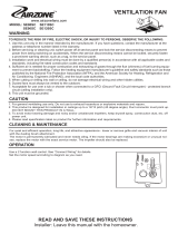
QTR / QTRE SERIES
VENTILATORS
READ AND SAVE THESE INSTRUCTIONS
CLEANING & MAINTENANCE
WARRANTY
Installer: Leave this manual with the homeowner.
For quiet and efficient operation, long life, and attractive appear-
ance - lower or remove grille and vacuum interior of unit with the
dusting brush attachment.
The motor is permanently lubricated and never needs oiling. If the
motor bearings are making excessive or unusual noises, replace
the blower assembly (includes motor and impeller).
OPERATION
Use an on/off switch or speed control to operate this ventilator. See
“Connect Wiring” for details.
Use of speed controls other than the
Broan Models 78V and 78W may cause a motor humming noise.
To register this product visit:
www.broan.com
BROAN THREE YEAR LIMITED WARRANTY
Broan warrants to the original consumer purchaser of its products that
such products will be free from defects in materials or workmanship for
a period of three years from the date of original purchase. THERE ARE
NO OTHER WARRANTIES, EXPRESS OR IMPLIED, INCLUDING, BUT
NOT LIMITED TO, IMPLIED WARRANTIES OF MERCHANTABILITY OR
FITNESS FOR A PARTICULAR PURPOSE.
During this three-year period, Broan will, at its option, repair or replace,
without charge, any product or part which is found to be defective under
normal use and service.
THIS WARRANTY DOES NOT EXTEND TO FLUORESCENT LAMP
STARTERS AND TUBES. This warranty does not cover (a) normal main-
tenance and service or (b) any products or parts which have been subject
to misuse, negligence, accident, improper maintenance or repair (other
than by Broan), faulty installation or installation contrary to recommended
installation instructions.
The duration of an implied warranty is limited to the three-year period as
specified for the express warranty. Some states do not allow limitation
on how long an implied warranty lasts, so the above limitation may not
apply to you.
BROAN’S OBLIGATION TO REPAIR OR REPLACE, AT BROAN’S OP-
TION, SHALL BE THE PURCHASER’S SOLE AND EXCLUSIVE REMEDY
UNDER THIS WARRANTY. BROAN SHALL NOT BE LIABLE FOR INCI-
DENTAL, CONSEQUENTIAL OR SPECIAL DAMAGES ARISING OUT OF
OR IN CONNECTION WITH PRODUCT USE OR PERFORMANCE. Some
states do not allow the exclusion or limitation of incidental or consequential
damages, so the above limitation may not apply to you.
This warranty gives you specific legal rights, and you may also have other
rights, which vary from state to state. This warranty supersedes all prior
warranties.
To qualify for warranty service, you must (a) notify Broan at the address
or telephone number stated below, (b) give the model number and part
identification and (c) describe the nature of any defect in the product or
part. At the time of requesting warranty service, you must present evidence
of the original purchase date.
Broan-NuTone LLC Hartford, Wisconsin
www.broan.com 800-558-1711