Reznor RA/D-350 Installation guide
- Category
- Space heaters
- Type
- Installation guide

Form I-RA/RAD350-HA, PN132209R2, Page 1
Applies to: Models RA/RAD 350
Installation Instructions for High Altitude Kit, Option DJ
Form I-RA/RAD350-HA
Obsoletes Form 464-HA
Option Description/
Application/
Components
DANGER:
This high altitude conversion kit should be installed by a qualied service agency in
accordance with these instructions and in compliance with all codes and requirements of
authorities having jurisdiction. Failure to follow instructions could result in death, serious
injury, and/or property damage. The qualied agency performing this work assumes
responsibility for this installation.
Installation
Instructions
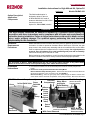
FIGURE 1 - Remote Pump Assembly
With Cover Removed
Pump
Enclosure
Oil
Pump
Cover
In-line Relief Valve
Ground Wire
(must be re-installed)
Gear
Motor
Electrical
Compartment
Motor Bracket
(remove assembled
bracket and motor)
Flexible Coupling
(loosen set screw
closest to motor)
Motor Wires
and Strain
Relief Bushing
Pump
Solenoid
Valve
Adhere
Remote
Pump
Lablel
(cover
original
pump
label)
This eld-installed option is
designed to allow for the use
of Model RA/RAD 350 used oil
heaters at altitudes from 3001-7000
feet above sea level.
Option DJ1, P/N 131808, includes:
Installation
Requirements/
Procedures
Qty Description P/N
1 Gear Pump Motor 131640
1 Motor Bracket 131632
4 Motor Mounting Screws 121338
1 Air Bleed Orice (#70) 132349
1 Rating Plate Field Modication Label 131595
1 Remote Pump Label 131597
2 Wire Nuts 16354
Model RA/RAD 350 used oil heaters are factory built for operation at sea level to 3000
ft elevation. In order to operate at elevations above 3000 feet to 7000 feet, the gear
pump motor in the remote pump assembly and the air manifold orice on the heater
must be replaced with the components in the option package. As original parts are
removed, keep all hardware to be used in attaching new parts and re-assembly.
Parts removed may not be returned for credit.
Before beginning actual installation, re-verify that the kit selected is appropriate for the
elevation. Follow the instructions closely to ensure safe and proper operation.
WARNING
This kit applies to Reznor
®
Model RA/RAD 350 only. Do not use this option package on any other heater
models or at elevations outside of the specied range (3001-7000 ft above sea level).
1. If the heater is installed, turn off the electrical power to both the remote pump and the
heater.
2. Remove the Factory-Installed Standard Gear Pump Motor
Remove Remote Pump Assembly Cover - Remove the sheet metal screws that attach the
remote pump assembly cover. Lift off the cover. See FIGURE 1.
Disconnect Wiring - Trace the gear pump motor leads through the bottom entrance hole
of the divider into the electrical compartment of the pump enclosure. Disconnect the motor
With Cover
in Place

Form I-RA/RAD350-HA, PN132209R2, Page 2
leads from the wire bundle (remove the wire nuts). Remove
the strain relief bushing and pull the motor leads through the
hole.
Remove the Motor and Bracket Assembly - The exible
coupling between the motor and the pump has two set
screws. Using an allen wrench, loosen the set screw closest
to the motor.
The motor is mounted on a bracket that is attached to the
pump enclosure. Do not attempt to remove the motor from
the bracket. Remove all of the screws, including the ground
wire screw, that hold the motor bracket to the pump enclo-
sure. Slide the motor shaft out of the coupling and remove the
assembled motor and bracket.
Save the green ground wire. The motor can either be put in
stock as a replacement part or discarded.
3. Assemble Motor, Bracket, and Ground Wire
Using the four screws (#10-23 x 3/8” long, Phillips head with a
lockwasher) furnished in the kit, attach the green ground wire
and the new gear motor to the new bracket..
4. Install the High Altitude Gear Pump Motor and Bracket
Assembly (Refer to FIGURE 1, page 1)
Attach the Motor/Bracket Assembly - Position the assem-
bled motor and bracket carefully, sliding the motor shaft into
the exible coupling. DO NOT TIGHTEN COUPLING SET
SCREW.
Attach the bracket to the pump enclosure by re-using the
same hardware.
Apply LOCKTITE 242 Threadlocker to the set screw and
tighten to 60 in-lbs.
Connect Wires - Insert the leads from the new motor through
the bottom hole in the divider into the electrical compartment
and re-install the strain relief bushing. Make the wire nut con-
nections.
Replacement of the gear motor pump is now complete. Posi-
tion the pump enclosure cover and secure it with the remain-
ing sheetmetal screws.
On the end of the pump enclosure locate the factory-installed
pump label (See FIGURE 1). Wipe the surface with a clean,
dry cloth. Afx the new high-altitude label so that it is covering
the original label.
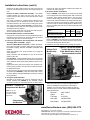
5. Change the Air Bleed Orice
Mounted on the service tray is the air compressor with an
integral manifold (See FIGURE 2). The manifold consists
of a brass tee with two hose barbs and the air bleed orice.
Installation Instructions (cont’d)
Unscrew the orice and discard. Install the #70 orice fur-
nished in the option package.
6. Re-Set Air Shutter and Air Band
Refer to FIGURE 3 and adjust the air shutter and air band
to the settings listed in the following table. With a clean heat
exchanger, these settings should result in the CO
2
range
shown, a smoke rating of less than No 1 on the Bacharach
smoke scale, and thermal efciencies of approximately 80%.
Follow the instructions in the “Start Up” Section of the heater
manual to verify the results actually obtained. Measure CO
2
with a hot system (after unit has run about 20 minutes) with
proper draft.
Model
Air
Shutter
Air
Band
CO
2
Range
RAD/RAD350 with DJ1 for
3001-7000 feet elevation
#4 #2
11-1/2 -
12-1/2%
7. Afx Field Modication label
Refer to FIGURE 3 and determine the recommended loca-
tion for this label. Be sure that the surface is clean and dry.
Peel off the backing and afx the label.
8. Installation of the high altitude option package is complete.
Follow the instructions in the manual supplied with the
heater for installation and operation. If the heater is
installed, re-connect the power and follow the start-up
instructions in the manual. CHECK FOR PROPER AND
SAFE OPERATION.
Elevation 3001-7000 Ft
Option DJ1
Fuel Input 2.10 GPH
Heat Input 294,000 BTUH
Heat Output 235,000 BTUH
Compressed
Air Manifold
FIGURE 2 - Location of
Compressed Air Manifold
Adhere Field
Modication
Label
Air Shutter
Air Band
Figure 3 - Re-set Air Shutter
and Air Band and Adhere
Field- Modication Label in
Recommended Location
www.ReznorHeaters.com; (855) 854-3172
©2015 Reznor, LLC. All rights reserved.
Trademark Note: Reznor
®
is registered in at least the United States. All other
trademarks are the property of their respective owners.
0514 (Serial No. Date Code BNE) Form I-RA/RAD350-HA (Version .2)
NOTE: Do not use
either TEFLON tape
or sealant on orice
plug threads.
-
 1
1
-
 2
2


Reznor RA/D-350 Installation guide
- Category
- Space heaters
- Type
- Installation guide
Ask a question and I''ll find the answer in the document
Finding information in a document is now easier with AI
Related papers
-
Reznor XL User manual
-
-
-
-
-
-
-
Reznor UDAS Installation & Operation Manual
-
Reznor UDAS 30 Installation & Operation Manual
-
Other documents
-
Thomas & Betts UDAS User manual
-
-
ICP H9MPD075F12C1 Installation guide
-
Ultrasone 13002 Datasheet
-
Sears N9MP1100F14B1 User manual
-
 GOODMAN GRL-09 Installation Instructions Manual
-
ICP H9UHX080J12A Installation guide
-
-
York DFAA User manual
-
Raypak 962-1826 User manual
