Page is loading ...

MFT70-US
Multifunction Tester
With On - board memory
User Manual

www.megger.com
2
Contents
Contents
SAFETY WARNINGS 5
Live Ground safety precautions ........................................................................................................................6
Symbols used on the instrument are: ..............................................................................................................7
Introduction 8
Overview .........................................................................................................................................................8
Front panel and controls ..................................................................................................................................8
Display .............................................................................................................................................................8
Display symbols ..............................................................................................................................................9
Waste electrical and electronic equipment......................................................................................................10
Battery and fuse location, fitting and replacement .........................................................................................10
To replace batteries or fuse: ...........................................................................................................................10
For battery replacement: ................................................................................................................................10
For fuse replacement .....................................................................................................................................10
Rechargeable batteries and battery charging ..................................................................................................10
To charge the batteries:..................................................................................................................................11
Operation 12
General operation – all models.......................................................................................................................12
Switching on ...............................................................................................................................................12
Switching off ..............................................................................................................................................12
Backlight .....................................................................................................................................................12
Test buttons .................................................................................................................................................12
Test button lock ..........................................................................................................................................12
Mode button functions ............................................................................................................................13
Test inhibit .....................................................................................................................................................13
Insulation .......................................................................................................................................................13
Continuity ....................................................................................................................................................13
GFCI testing ...................................................................................................................................................13
Ground testing ..............................................................................................................................................13
Battery exhausted ..........................................................................................................................................13
Voltage, frequency, current and temperature measurement............................................................................14
Making a voltage measurement .....................................................................................................................14
OR if using the mains plug lead SAI10:...........................................................................................................14
Frequency measurement ................................................................................................................................15
Phase rotation ................................................................................................................................................15
Leakage current measurement ......................................................................................................................15
Temperature measurement ............................................................................................................................15
Switch probe .................................................................................................................................................15
Continuity / resistance measurement ..............................................................................................................16
Nulling test lead resistance (up to 9.99 ohms)
W
.........................................................................................16

www.megger.com
3
Contents
To null test leads: ........................................................................................................................16
Making a continuity measurement .................................................................................................................17
Storing / downloading results .........................................................................................................................17
Continuity Buzzer ON/OFF..............................................................................................................................17
Switch probe (SP5) .........................................................................................................................................18
Buzzer threshold ............................................................................................................................................18
Measurement methods and sources of error ..................................................................................................18
Method of measurement .............................................................................................................................18
Possible sources of error ...............................................................................................................................18
Insulation resistance
500
V
.............................................................................18
Making an insulation measurement ...............................................................................................................19
Insulation test lock .......................................................................................................................................19
Measurement methods and sources of error ..................................................................................................20
Ground Fault Current Interrupt (GFCI) testing ................................................................................................20
Function button options ....................................................................................................................20
Ramp test ....................................................................................................................................................20
Making a measurement ...............................................................................................................................20
Touch voltage display ...................................................................................................................................21
Measurement methods and sources of error ................................................................................................21
Useful information .......................................................................................................................................22
Ground resistance measurement ....................................................................................................................22
Connection terminals ...................................................................................................................................22
Touch voltage limit .......................................................................................................................................22
Making a measurement - two pole resistance measurement ........................................................................22
Making a measurement – three terminal resistance measurement ...............................................................23
Making a measurement – three terminal resistance measurement using ART ...............................................24
Two-clamp stake-less measurement .............................................................................................................25
Setup options 26
Warning messages .........................................................................................................................................27
Startup warnings ........................................................................................................................................27
Battery .........................................................................................................................................................27
Battery charger ............................................................................................................................................27
Fuse warning ...............................................................................................................................................27
Invalid rotary switch setting .........................................................................................................................27
Continuity test .............................................................................................................................................27
Insulation test ..............................................................................................................................................27
GFCI Test ....................................................................................................................................................27
GFCI range selection errors ..........................................................................................................................27
Test will not start ........................................................................................................................................28
Sending, Storing, Deleting and Recalling Test Results......................................................................................29

www.megger.com
4
Contents
Folders: ........................................................................................................................................................29
Circuit type: .................................................................................................................................................29
Insulation: ....................................................................................................................................................29
GFCI: ...........................................................................................................................................................30
Ground testing: ...........................................................................................................................................30
Storing Test Results in the internal memory ....................................................................................................30
Deleting Test Results from the internal memory ............................................................................................30
Recalling Test Results to the display ..............................................................................................................31
Sending stored test results via Bluetooth
®
....................................................................................................31
Sending individual (Blobbing) test results......................................................................................................31
Continuity testing ........................................................................................................................................32
GFCI testing .................................................................................................................................................32
Ground testing ...........................................................................................................................................32
Bluetooth
®
Pairing .........................................................................................................................................33
Bluetooth
®
Pairing (PC or Laptop) ................................................................................................................33
General Information 34
Installation category definitions ....................................................................................................................34
Safe working practice ..................................................................................................................................34
Cleaning and maintenance ..........................................................................................................................34
Ground resistance testing – Basic principles ....................................................................................................35
Principle of operation (three-terminal resistance measurement) ....................................................................35
Principle of operation (three-terminal resistance measurement using ART) ....................................................35
Principle of operation (two-clamp stake-less resistance measurement) ..........................................................36
General Specification .....................................................................................................................................37
Repair and Warranty ....................................................................................................................................39
CALIBRATION, REPAIR AND SPARE PARTS .....................................................................................................39
Deceleration of Conformity .............................................................................................................................

www.megger.com
5
SAFETY WARNINGS
SAFETY WARNINGS
Safety warnings and precautions must be read and understood before the instrument is used.
They must be observed during use.
Warnings:
• The circuit under test must be switched off, de-energised and isolated before test connections are
made when carrying out insulation and continuity tests.
• Continuity of protective conductors and Grounded equipotential bonding of new or modified
installations must be verified before carrying out an Ground fault loop impedance test, GFCI or
Ground testing
• Do not touch circuit connections and exposed metalwork of an installation or equipment under
test. Under fault conditions the system Ground could become hazardous live.
• Do not touch the Ground stakes, test leads and their terminations (including connections to
the Grounding system under test) if an installation Ground fault can arise, unless adequate
precautions are taken.
• The ‘live circuit warning’ and ‘automatic discharge’ functions are additional safety features and
should not be regarded as a substitute for normal safe working practices.
• Do not move the rotary switch positions while a test is in progress.
• Do not operate the instrument or connect it to any external system if it shows any visible signs
of damage or if it has been stored for prolonged periods in unfavourable conditions.
• Do not operate the instrument or connect it to any external system if the battery compartment
or casing is open or any parts of the case (including keypad, selector switch, display window,
etc.) are missing.
• Always disconnect the instrument from all systems while batteries are being changed or the fuse
replaced
• Do not replace rechargeable cells in the instrument with non-rechargeable “dry” cells and
attempt to charge the cells. This can cause explosion or fire.
• Do not operate charging equipment supplied with the instrument in damp or wet environments
or outdoors. All test leads must be removed from the instrument while charging.
• After insulation tests, capacitive circuits must be allowed to discharge before disconnecting
test leads. Locking the insulation test ON should only be used where there is no risk of a circuit
holding a charge.
• The instrument should not be used if any part of it is damaged.
• Test leads, probes and crocodile clips must be in good order, clean and with no broken or cracked
insulation.
• All test leads supplied with the instrument form part of the measuring circuit of the instrument.
They must not be modified or changed in any way, or be used with any other electrical
instrument or appliance.
• A plug severed from the power cord MUST be destroyed, as a plug with bare conductors is
hazardous in a live socket outlet.
• Ensure that hands remain behind guards of probes/clips when testing.
• U.K. Safety Authorities recommend the use of fused test leads when measuring voltage on high
energy systems.
• Replacement fuses must be of the correct type and rating.
• Failure to fit the correctly rated fuse will result in damage to the instrument in the event of an
overload.
• Special precautions are necessary when operating in situations where “live” Grounds may be
encountered: isolation switches and fuses (not supplied with this instrument) must be used.

www.megger.com
6
SAFETY WARNINGS
• Special precautions are necessary when working near high tension systems (MV and HV):
rubber gloves and shoes (not supplied with this instrument) should be worn.
• Special precautions are necessary when working in wet conditions or in agricultural
areas: observe the local safety standards and take all necessary special precautions applicable to
the particular location and do not touch the test leads with bare hands.
Live Ground safety precautions
A ‘Live’ ground is one that carries current from the mains supply, or could do so under fault conditions. The
following warnings apply in addition to those listed previously.
Warnings:
• All persons involved must be trained and competent in isolation and safety procedures for the
system to be worked on. They must be clearly instructed not to touch the Ground electrode,
test stakes, test leads, or their terminations if any ‘Live’ Grounds may be encountered. It is
recommended that they wear appropriate rubber gloves, rubber soled shoes, and stand on a
rubber mat.
• The Ground electrode under test should be isolated from the circuit it is protecting before testing
commences. If this is not possible, ART (attached Rod Technique) may be used to measure
electrode resistance.
• The instrument terminals should be connected to the system under test through isolation
switches that are rated to handle the likely maximum fault voltages and currents that could be
encountered at the installation. The isolation switch must be open whilst any personal contact
is made with the remote test stakes, or the connecting leads, e.g. when changing their position.
• The instrument terminals should be connected to the system under test through fuses that are
rated to handle the likely maximum fault voltages and currents that could be encountered at the
installation.
Note: This instrument must only be operated by suitably trained and competent people.
Users of this equipment and/or their employers are reminded that Health and Safety Legislation requires them to
carry out valid risk assessments of all electrical work so as to identify potential sources of electrical danger and risk
of electrical injury such as inadvertent short circuits. Where the assessments show that the risk is significant then
the use of fused test leads constructed in accordance with the HSE guidance not GS38 ‘Electrical Test Equipment
for use by Electricians’ should be used .
This instrument is internally protected against electrical damage when used for the purposes of testing low voltage
electrical installations as defined herein. If used in a manor other than those defined in this user guide, the
protection capabilities could be impaired with potential risk to the operator and the instrument.

www.megger.com
7
SAFETY WARNINGS
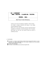
Symbols used on the instrument are:
G
Caution: Refer to accompanying notes
Maximum 300 V a.c. CAT IV to Ground
> 600 V
Maximum nominal system voltage of 600 V
f
Instrument protected by 2 x F2 1000 V 30 kA fuses
c
Equipment complies with current EU Directives
This equipment should be recycled as electronic waste
Equipment complies with ‘C tick’ requirements
12 V DC charger socket

www.megger.com
8
Introduction
Introduction
Congratulations on your purchase of a genuine Megger Multifunction tester. The MFT70 series Multi-function tester is a
compact instrument designed to perform all of the functions required by the electrical contractor to fully test domestic,
commercial and industrial wiring. Specially designed to comply with modern US International wiring regulations and
standards, the MFT70 may be used on all single and three phase systems with rated voltages up to 300 V AC rms to
ground.
Overview
Front panel and controls
Display
Test button
Lead Null
Test lock
Setup selector
Results store
Test lock
Setup selector
Touch voltage
contact point
Mode
Display
backlight
Display
Primary
functions
Secondary
functions
Test button
Lead Null

www.megger.com
9
Introduction
Display symbols
Symbol Meaning Symbol Meaning
l
Test function locked on (also used to
indicate a change is saved in setup)
G
Warning triangle – instruction to refer to
this user guide
z
Test lead null active
f
Fuse blown
U
L
= 50V
Touch voltage limit (and Ground test
voltage) set to 50 V (change setup)
Battery indicator
Buzzer enabled NiMH
Battery type set to rechargeable NiMH -
Change in “Battery” on page 27
AUTO
GFCI test in AUTO mode >100 V
Indicates that the ground noise voltage
exceeds the instrument measurement
capability (test is inhibited)
Type AC GFCI selected Rp (Rs)
Potential stake (P stake)
resistance exceeds range for accurate
measurement
Type A GFCI selected Rc (RH)
Current stake (C Stake)
resistance exceeds range for accurate
measurement
S
Type S GFCI (Type AC)
V
Ground noise voltage exceeds range for
accurate measurement of resistance
S
Type S GFCI (Type A)
V
Megger Voltage Clamp error
Type B GFCI selected
I
Megger Current Clamp error
Fast or Full RAMP test selected Bluetooth
®
enabled
TEST
Instrument is running a test
T
Instrument is too hot, allow to cool
Ground loop noise detected.
N<->L Live and neutral connections reversed
Zref Reference loop measurement
R1+R2
Loop measurement with Zref value
automatically deducted
ZMAX
Loop maximum measurement
NOTE: Some features detailed within this user guide are model dependent. Not all features appear on all models.

www.megger.com
10
Introduction
Waste electrical and electronic equipment
WEEE
The crossed out wheeled bin placed on Megger products is a reminder not to dispose of the product at the
end of its life with general waste. Follow local regulations.
Megger is registered in the UK as a producer of electrical and electronic equipment. The registration number
is WEE/HE0146QT
Battery and fuse location, fitting and replacement
Battery type: 6 x 1.5 V Alkaline LR6 (AA) or NiMH HR6 rechargeable
Fuse type: 2 x F2 1000 V 30 kA fuses
Battery condition is shown by the following display symbols:
Where NiMH rechargeable batteries are fitted, the battery condition display can be adjusted accordingly. Refer to
“Setup options” on page 26 to change between alkaline and rechargeable batteries.
When set to NiMH batteries, the battery indicator in the display will show NiMH under the battery status symbol
as below: (Feature available on all models).
To replace batteries or fuse:
Switch off the instrument.
Disconnect the instrument from any electrical circuits.
Remove the battery cover from the base.
For battery replacement:
Remove old cells and refit new batteries following correct polarity as marked on the battery holder.
Replace the battery cover.
Incorrect battery cell polarity can cause electrolyte leakage, resulting in damage to the instrument.
For fuse replacement
Withdraw each fuse in turn and check for failure. The blown fuse must be replaced with a F2 1000 V 30 kA fuse.
Rechargeable batteries and battery charging
Some models are supplied with rechargeable NiMH cells. These batteries can be charged in the instrument, using
the supplied Megger charger.
NiMH

www.megger.com
11
Introduction
To charge the batteries:
Ensure fitted batteries are of the rechargeable NiMH type (as shown above).
Connect the 12 V dc plug of the charger to the socket on the front of the MFT marked
Warning:
• Whenever battery cells are being recharged, there should be no connections to the instrument
terminals and the instrument should be switched off.
• Do not attempt to recharge non-rechargeable (Primary) cells. Doing so may result in instrument
damage and may cause personal injury.
Ensure ambient temperatures are between 4º C and 40º C while charging the MFT.
Note: The crossed out wheeled bin placed on the batteries is a reminder not to dispose of them with general
waste at the end of their life.
Spent Alkaline and NiMH batteries are classified as portable batteries and should be disposed of in accordance
with local regulations.
Megger is registered in the UK as a producer of batteries. The registration number is BPRN00142

www.megger.com
12
Operation
Operation
General operation – all models
Switching on
Turn the left hand rotary knob away from the off position.
The instrument will perform internal self tests then display the appropriate test screen, depending on the position
of the function knobs.
Switching off
Turn the primary function (left hand rotary) knob to the OFF position.
The instrument will automatically turn itself off after 20 minutes* of inactivity. Press any button or turn either of
the rotary knobs to turn back on.
* 2 minute option in Setup, refer to “Setup options” on page 26.
Backlight
Press the backlight button. The backlight will operate for 20 seconds.
Test buttons
The test buttons, or , are duplicated on the left and right of the unit. Both buttons perform the same
function except, when the is displayed, in this case the right hand buttons perform a scrolling function. The
left RED button also performs bluetooth, storage and lock functions.
Test button lock
To lock the test button, hold down either of the RED test lock buttons with the L symbol, whilst holding down
the test button. If is displayed, the right hand buttons perform a scrolling function.

www.megger.com
13
Operation
Mode button functions
The function of the mode button is dependent on the test function selected:
Test selected Function Options Comments
V/º C Volts / mV Temperature requires suitable transducer
Continuity
RLO
Buzzer
ENABLE/DISABLE
Buzzer ON
Buzzer OFF
Buzzes on <2 Ω
May be changed in SETUP.
Refer to “Setup options” on page 26.
Insulation
RSIO
Buzzer
ENABLE/DISABLE
Buzzer ON
Buzzer OFF
Buzzes on <1 MΩ
May be changed in SETUP.
Refer to “Setup options” on page 26.
GFCI
0º / 180º
selection
0º
180º
(Press and release)
GFCI Type
AC
A
AC(s)
A(s)
B
(Press and HOLD)
Ground (RE) Touch voltage limit 50 V / 25 V Press and release
SETUP
Refer to instrument
setup “Setup options”
on page 26.
Test inhibit
Each test mode has conditions under which testing will be inhibited, as below:
Insulation
Detection of a circuit voltage above 50 V (a warning is displayed at 25 V).
Continuity
Detection of a circuit voltage above that used by the instrument will inhibit testing.
GFCI testing
Touch voltage detected or predicted to exceed 50 V (or 25 V depending on instrument configuration).
Supply voltage over range or under range.
Supply Frequency out of specification.
Ground testing
External voltage greater than 25 V present.
Leads not connected as per the test requirements.
Potential stake not within range (Rp).
Current stake not within range (Rc).
Other conditions that will inhibit testing include:
Battery exhausted
All testing will be inhibited in the event of a flat battery, refer to “Battery and fuse location, fitting and
replacement” on page 10.

www.megger.com
14
Operation
Voltage, frequency, current and temperature measurement
Making a voltage measurement
1. Set the Main rotary range knob to volts
(The position of the right hand rotary range knob must not be in the position.)
2. Using two test leads, connect test leads to the L1 (+ve) and L2 (-ve) terminals
L1
L2
L3
N
E
L1
L2
L3
N
E
OR if using the mains plug lead SAI10:
a. For live to neutral measurements, connect the red connector to the L1 terminal and the blue connector to
the L2 terminal
b. For live to ground measurements connect the red test to the L1 terminal and the green connector to the
L2 terminal
L1
N
E
L1
N
E
Connection (a) Connection (b)
Note: When connecting all three test leads (eg phase, neutral and ground) or the mains plug test lead, the
voltage displayed is the highest of the three possible voltages.
Pressing either TEST button scrolls through L-E, N-E and L-N individual voltages. When the frequency of supply is
shown, the voltage displayed reverts to the maximum voltage across all 3 terminals.
Use the Mode button to select mV mode.

www.megger.com
15
Operation
Frequency measurement
Automatically displayed when connecting to a live circuit refer to “Making a voltage measurement” on page 14
Phase rotation
Display of Phase rotation is automatic when all three test leads are connected to the 3 phase supply as below:
1. Set the main rotary range knob to volts
V
(The position of the right hand rotary range knob must not be in the position.)
2. Using three test leads, connect test leads to the L1 to Phase1, L2 to Phase 2 and L3 to Phase 3. The MFT will
display L1 L2 L3 or L1 L3 L2 depending on the direction of phase rotation.
L1
L2
L3
Normal rotation Reverse rotation
Leakage current measurement
Leakage current measurement uses the optional accessory current clamp (Megger Current Clamp).
1. On the MFT70, set the primary range knob to clamp position .
2. Connect to Megger Current Clamp (part number MCC1010) to the Megger Current Clamp socket on
the MFT.
3. Connect the clamp to the circuit conductor. The MFT will display the (AC) current flowing in the conductor.
Temperature measurement
1. Connect the thermocouple transducer to the L1 (+ve) and L2 (-ve) terminals.
2. Press the Mode button to select º C. (Pressing the mode button will cycle round the V, mV and º C
measurement modes.)
The display will show the temperature at the tip of the temperature probe.
Switch probe
In the V / mV / º C mode all measurements except temperature can be made with the remote switch probe. Tests
are automatic and do not require the test button to be pressed.
Connect the switch probe to the switch probe socket. The probe replaces the standard RED test lead and can
now be used as a normal test probe.
L1
L2
L3
N
E

www.megger.com
16
Operation
Continuity / resistance measurement
NOTE: The continuity test will auto-range from 0.01 Ω to 99.9 kΩ. Circuits up to 2 Ω will be tested at >200 mA.
To change the test current refer to “Setup options” on page 26.
NOTE: The continuity test is automatic. Testing starts as soon as the leads are connected to a circuit. The
TEST
button is ONLY used to null the lead set.
Warning:
Prior to any continuity testing, ensure the circuits under test are isolated and not live.
SETUP allows the follow configuration options:
Positive test current
Bi-directional test current
Bi-directional test current allows the automatic testing of the circuit in both directions and the highest measured
value being displayed refer to “Setup options” on page 26.
Nulling test lead resistance (up to 9.99 ohms)
W
Before starting a continuity test, the test lead resistance should be nulled such that it does not add extra resistance
to the circuit being measured. Once nulled it does not need repeating for each test. Periodically it should be
checked to ensure nothing has changed.
The “Lead Null” value is retained even when the tester is switched off.
To null test leads:
Short test probes or clips together and press the
TEST
button. The null symbol z will be displayed to indicate
lead null is active.
Lead null OFF
This null value is stored until the
TEST
button is pressed again.
To cancel the LEAD NULL, separate the test leads and press the
TEST
button.

www.megger.com
17
Operation
Making a continuity measurement
1. Set the Primary (Left) range knob to
W
range. (The position of the right hand rotary range knob must not be
in the position.)
2. Connect two test leads to the L1 (+ve) and L2 (-ve) terminals on the instrument. A continuity measurement is
made automatically.
L
N
E
g
NOTE: Measurements are prevented when:
NOTE: A resistance of > 99.9 kΩ is present
NOTE: Circuit voltages in excess of 4 V are detected.
Storing / downloading results
Once the display shows a value it will automatically be logged into temporary memory. Unless stored, this will be
over written by the next measurement.
To store this result or to send it to a compatible device, refer to “Sending, Storing, Deleting and Recalling Test
Results” on page 29.
Continuity Buzzer ON/OFF
Whilst in the continuity range, press the MODE button . This will toggle the buzzer ON and OFF.
Buzzer ON =
Buzzer OFF = No symbol

www.megger.com
18
Operation
Switch probe (SP5)
In CONTINUITY/RESISTANCE mode all measurements can be made with the remote switch probe (SP5). Tests are
automatic and do not require the
TEST
button to be pressed.
Connect the switch probe to the switch probe socket L1 (+ve). The switch probe replaces the standard RED test
lead as in ‘Making a continuity measurement’ above.
Buzzer threshold
If the measured resistance is less than the buzzer threshold, the buzzer will sound. The resistance at which the
buzzer stops sounding can be changed to meet individual test requirements. Refer to “Setup options” on
page 26 of this guide.
Selectable limits of 0.5 Ω, 1 Ω, 2 Ω, 5 Ω, 10 Ω, 20 Ω, 50 Ω, 100 Ω, are available.
This setting is stored even when the instrument is switched off.
Measurement methods and sources of error
Method of measurement
The 2-wire lead set must be used for this measurement. A DC voltage of nominally 4.4 V with a current limit of
>200 mA is used to measure resistance less than 2 Ω.
Possible sources of error
Measurement results can be affected by the following:
The presence of circuits connected in parallel.
Presence of AC voltages on the circuit being measured.
A poor connection to the circuit under test.
Incorrectly nulled test leads.
Use of fused leads.
Insulation resistance
500
V
NOTE: The insulation test is protected by a live circuit warning. Detection of a voltage over 50 V will inhibit
testing. This applies whether or not the insulation test is locked on.

www.megger.com
19
Operation
Making an insulation measurement
1. Set the left hand rotary range knob to the
500
V
insulation test voltage required. (The position of the right hand
rotary range knob must not be in the position.)
2. Connect two test leads to the L1 (+ve ) and L2 (-ve) terminals on the instrument.
L1
L2
L3
N
E
3. To start test, press and hold either of the
TEST
buttons, or , on the instrument.
Release the test button after the displayed reading has settled. The circuit will now discharge safely.
Note: A 1000 V warning is displayed whenever the 1000 V range is selected for the first time and the
TEST
button is pressed.
Insulation test lock
To lock an insulation test ON, hold down either of the
TEST
buttons followed by either of the RED LOCK
buttons.
To release the “Locked on” insulation test, press the
TEST
button.
Warnings:
• The test voltage will be permanently present on the test probes or crocodile clips when in the
locked position.
• Auto discharge - Auto discharge facility automatically and safely discharges the circuit at the
completion of an insulation test.
• Live circuit warning - operates when connected to live circuits > 25 V. Testing is still permitted.
• Test inhibited - Live circuits > 50 V will inhibit testing.

www.megger.com
20
Operation
Measurement methods and sources of error
The selected DC test voltage (current limited to less than 2 mA DC) is applied to the circuit under test and the
resistance is calculated from measurements of the resulting voltage and current.
Capacitive circuits can take some time to charge. This is displayed as an increasing voltage that takes longer to
reach its maximum than normal.
The reading is stable with a circuit capacitance less than 5 µF.
Ground Fault Current Interrupt (GFCI) testing
The MFT70 can perform a ramp test on a 6 mA GFCI which introduces a current to ensure it trips under fault
conditions.
This GFCI test meets the requirements of GFCI Type A as defined in the ANSI/UL 943, CSA C22.2 No. 144.1 and
ANCE NMX-J-520.
Function button options
Short press - 0º / 180º starts the test on a positive or negative half cycle.
Hold 2s press – AC / A / S / B type
Note: When testing GFCIs the test mode should be left in AC which is set as default. The other modes
are not relevant for GFCI testing. If another mode is selected unintentionally, e.g. A , S
S
or B , then
the mode button
can be held down for 2 seconds to change the mode. Repeat this until the A symbol is
displayed at the bottom of the display.
Ramp test
The GFCI trip current is measured by applying a test current and increasing this every 300 ms. When the GFCI trips,
the current flowing is recorded and displayed in mA if it is close to the rated current of the GFCI i.e. between 5-6
mA, to a resolution of 100 µA. Alternatively the display will show a ‘trp’ message to showing the GFCI has tripped.
Making a measurement
1. Select the GFCI
GFCI
option on the right hand rotary switch.
2. Select the RAMP test on the left hand range rotary switch.
3. Connect the instrument Phase (L1) and Ground (L2) terminals to the GFCI phase and ground terminals (or to
the phase and ground of the circuit the GFCI is protecting). Use either the separate leads or mains plug leads.
RCD
g
L
N
E
MCB
L
N
E
MCB
g
/