Page is loading ...

1
Use & Care Guide
Model No.
153.582400 40 Gallon Tall
153.582500 50 Gallon Tall
P/N 100272307 (0516)
Sears Brands Management Corporation,
Hoffman Estates, IL 60179 U.S.A.
www.kenmore.com
LOW LEAD
CONTENT
Kenmore®
Electric
Water Heater
For potable water heating only.
Not suitable for space heating.
INSTALLER: Affi x these instructions to or near
the water heater.
OWNER: Retain these instructions for future
reference.
Si no puede leer o entender el inglés y necesita el manual de
instrucciones en español, puede solicitarlo al 1-800-821-2017. NO
TRATE DE INSTALAR U OPERAR ESTE CALENTADOR DE AGUA
SI NO ENTIENDE LAS INSTRUCCIONES. No hacer caso de esta
advertencia podría originar lesiones graves o mortales.
ADVERTENCIA

2
Your safety and the safety of others is extremely important in the installation, use and servicing of this water heater.
Many safety-related messages and instructions have been provided in this manual and on your own water heater to warn
you and others of a potential injury hazard. Read and obey all safety messages and instructions throughout this manual.
It is very important that the meaning of each safety message is understood by you and others who install, use or service
this water heater.
All safety messages will generally tell you about the type of hazard, what can happen if you do not follow the safety message
and how to avoid the risk of injury.
IMPORTANT DEFINITIONS
• Sears Service Center: The Sears Service Center has the ability equivalent to a licensed tradesman in the fi elds of plumbing and
electrical work including a thorough understanding of the requirements of the National Electrical Code as it relates to the installation
of electric water heaters. The Sears Service Center also has a thorough understanding of this instruction manual, and is able to
perform repairs strictly in accordance with the service guidelines provided by the manufacturer.
This is the safety alert symbol. It is used to alert you
to potential personal injury hazards. Obey all safety
messages that follow this symbol to avoid possible
injury or death.
DANGER
WARNING
CAUTION
DANGER indicates an imminently hazardous
situation which, if not avoided,
will result in death or injury.
CAUTION
WARNING indicates a potentially
hazardous situation which, if not avoided,
could result in death or injury.
CAUTION indicates a potentially hazardous
situation which, if not avoided, could
result in minor or moderate injury.
CAUTION used without the safety alert
symbol indicates a potentially hazardous
situation which, if not avoided, could
result in property damage.
SAFE INSTALLATION, USE AND SERVICE
© Sears Brands LLC

3
GENERAL SAFETY

4
TABLE OF CONTENTS
Contents
SAFE INSTALLATION, USE AND SERVICE...................................................................................................................................................2
GENERAL SAFETY......................................................................................................................................................................................... 3
PRODUCT WARRANTY ................................................................................................................................................................................. 5
INTRODUCTION .............................................................................................................................................................................................6
PRODUCT SPECIFICATIONS ........................................................................................................................................................................ 6
MATERIALS AND BASIC TOOLS NEEDED ................................................................................................................................................... 7
Removing the Old Water Heater ...................................................................................................................................................... 8
INSTALLATION INSTRUCTIONS ................................................................................................................................................................... 8
Wiring ...............................................................................................................................................................................................9
Water Piping ................................................................................................................................................................................... 11
Temperature-Pressure Relief Valve ................................................................................................................................................ 12
Filling the Water Heater .................................................................................................................................................................. 13
Wiring Diagram .............................................................................................................................................................................. 14
Installation Checklist ...................................................................................................................................................................... 15
KENMORE
®
SMART WATER HEATER MODULE (SOLD SEPARATELY) ................................................................................................... 16
OPERATING YOUR WATER HEATER ......................................................................................................................................................... 17
Water Heater Start-Up .................................................................................................................................................................... 17
Safety Shut-Off ............................................................................................................................................................................... 17
Water Temperature Regulation ...................................................................................................................................................... 17
Modes and Adjustments ................................................................................................................................................................. 18
Water Temperature Adjustment ....................................................................................................................................... 18
Operating Mode Descriptions ......................................................................................................................................... 18
The Electronic Thermostat .............................................................................................................................................................19
Diagnostic LED Light ...................................................................................................................................................................... 19
Overriding The Energy Saver Module (ESM) ................................................................................................................................. 19
SERVICE AND ADJUSTMENT ..................................................................................................................................................................... 20
Anode Rod Inspection .................................................................................................................................................................... 20
Temperature-Pressure Relief Valve Operation ..........................................................................................................................20-21
Draining and Flushing .................................................................................................................................................................... 21
Heating Element Replacement .................................................................................................................................................21-22
Service ...........................................................................................................................................................................................22
TROUBLESHOOTING ..................................................................................................................................................................................23
Start Up Conditions ........................................................................................................................................................................23
Closed System/Thermal Expansion ................................................................................................................................ 23
Strange Sounds .............................................................................................................................................................. 23
Operational Conditions ................................................................................................................................................................... 23
Smelly Water ..............................................................................................................................................................23-24
“Air” in Hot Water Faucets ...............................................................................................................................................24
Rumbling Noise ............................................................................................................................................................... 24
High Temperature Shut Off System ................................................................................................................................ 24
Not Enough or No Hot Water .......................................................................................................................................... 25
Water Is Too Hot ............................................................................................................................................................. 25
Stacking ..........................................................................................................................................................................25
Diagnostic Code Chart: Energy Saver Module (ESM) .............................................................................................................26-27
Diagnostic Code Chart: Electronic Thermostat (ET) ................................................................................................................28-29
Troubleshooting Chart .................................................................................................................................................................... 30
LEAKAGE CHECKPOINTS ...........................................................................................................................................................................31
REPAIR PARTS LIST .................................................................................................................................................................................... 32
NOTES .....................................................................................................................................................................................................33-35

5
PRODUCT WARRANTY
KENMORE LIMITED WARRANTY
WITH PROOF OF SALE, the following warranty coverage applies
when this water heater is correctly connected, installed, operated and
maintained according to all supplied instructions. In all cases, replace-
ment units, tanks or parts are warranted only for the unexpired portion
of the warranty period from the original date of sale.
FOR ONE YEAR from the date of sale this water heater is warranted
against defects in material or workmanship. A defective water heater
will receive free repair or replacement at option of seller.
FOR TWELVE YEARS from the date of sale this water heater is war-
ranted against leaks in the tank. If a tank leak occurs within the fi rst
year, a new water heater of equal capacity and quality will be supplied
and installed at no charge. If a tank leak occurs after the fi rst year, a
new water heater of equal capacity and quality will be supplied but not
installed at no charge. You are responsible for the labor cost of water
heater installation after the fi rst year from the date of sale.
FOR TWELVE YEARS from the date of sale all water heater parts
are warranted against defects in material or workmanship. If a part is
defective within the fi rst year, a new part will be supplied and installed
at no charge. If a part is defective after the fi rst year, a new part will
be supplied but not installed at no charge. You are responsible for the
labor cost of part installation after the fi rst year from the date of sale.
For warranty coverage details to obtain free repair or replacement,
visit the web page: www.kenmore.com/warranty
This warranty applies for only two years on the tank and one year on
all parts if this water heater is ever used in a residence of more than
one family or in a commercial, institutional or industrial installation.
This warranty covers ONLY defects in material and workmanship,
and will NOT pay for:
1. Expendable items that can wear out from normal use, including but
not limited to fi lters, belts, bags or screw-in base light bulbs.
2. A service technician to clean or maintain this appliance, or to instruct
the user in correct appliance installation, operation and maintenance.
3. Service calls to correct appliance installation not performed by Sears
authorized service agents, or to repair problems with house fuses,
circuit breakers, house wiring, and plumbing or gas supply systems
resulting from such installation.
4. Damage to or failure of this appliance resulting from installation not
performed by Sears authorized service agents, including installation
that was not in accord with electrical, gas or plumbing codes.
5. Damage to or failure of this appliance, including discoloration or
surface rust, if it is not correctly operated and maintained according
to all supplied instructions.
6. Damage to or failure of this appliance, including discoloration or
surface rust, resulting from accident, alteration, abuse, misuse or
use for other than its intended purpose.
7. Damage to or failure of this appliance, including discoloration or
surface rust, caused by the use of detergents, cleaners, chemicals
or utensils other than those recommended in all instructions supplied
with the product.
8. Damage to or failure of parts or systems resulting from unauthorized
modifi cations made to this appliance.
9. Service to an appliance if the model and serial plate is missing,
altered, or cannot easily be determined to have the appropriate
certifi cation logo.
Disclaimer of implied warranties; limitation of remedies
Customer’s sole and exclusive remedy under this limited warranty
shall be product repair or replacement as provided herein. Implied
warranties, including warranties of merchantability or fi tness for a
particular purpose, are limited to one year on the water heater, and
twelve years on the tank and parts, or the shortest period allowed by
law. Seller shall not be liable for incidental or consequential damages.
Some states do not allow the exclusion or limitation of incidental or
consequential damages, or limitation on the duration of implied war-
ranties of merchantability or fi tness, so these exclusions or limitations
may not apply to you.
This warranty applies only while this appliance is used in the United
States.
This warranty gives you specifi c legal rights, and you may also have
other rights which vary from state to state.
Sears Brands Management Corporation,
Hoffman Estates, IL 60179
Master Protection Agreements
Congratulations on making a smart purchase. Your new Kenmore®
product is designed and manufactured for years of dependable
operation. But like all products, it may require preventive maintenance
or repair from time to time. That’s when having a Master Protection
Agreement can save you money and aggravation.
The Master Protection Agreement also helps extend the life of your
new product. Here’s what the Agreement* includes:
• Parts and labor not just for repairing defects, but to help keep
products operating properly under normal use. Our coverage goes
well beyond the product warranty. No deductibles, no functional
failure excluded from coverage— real protection.
• Expert service by experienced service technicians trusted in
millions of homes every year.
• Unlimited service calls and nationwide service, as often as you
want us, whenever you want us.
• “No-lemon” guarantee – replacement of your covered product after
three separate product failures occur within twelve months and a
fourth repair is required. Includes free delivery and installation, if
necessary, of replacement product.
• Product replacement if your covered product can’t be fi xed.
• Annual Preventive Maintenance Check at your request – no
extra charge.
• Fast help by phone – phone support from a service agent on all products
to help trouble-shoot problems. Think of us as a “talking owner’s manual.”
• Power surge protection against electrical damage due to power
fl uctuations.
• $300 Food Loss Protection for any food spoilage that is the result
of mechanical failure of any covered refrigerator or freezer.
• Service Promise: $50 if fi rst attempt repair of your covered kitchen
or laundry product can’t be accomplished and product is not usable
while awaiting further repair service.
• 25% discount off the regular price of any non-covered repair service
and related installed parts.
Once you purchase the Agreement, a simple phone call is all that it
takes for you to schedule service. You can call anytime day or night.
The Master Protection Agreement is a risk free purchase. If you cancel
for any reason during the product warranty period, we will provide a
full refund. Or, a prorated refund anytime after the product warranty
period expires. Purchase your Master Protection Agreement today!
Some limitations and exclusions apply. For prices and additional
information in the U.S.A. call 1-800-827-6655.
* Coverage in Canada varies on some items. For full details call
Sears Canada at 1-800-361-6665.
Sears Installation Service
For Sears professional installation of home appliances, garage door
openers, water heaters, and other major home items, in the U.S.A. call
1-844-553-6667, and in Canada call 1-800-469-4663.

6
Thank You for purchasing a Kenmore water heater. Properly
installed and maintained, it should give you years of trouble
free service. It is strongly suggested that this new water heater
be professionally installed. Contact the local Sears Service
Center or any Sears store. They will arrange for prompt, quality
installation by Sears authorized contractors.
Abbreviations Found In This Instruction Manual:
UL – Underwriters Laboratories Inc.
NEC – National Electrical Code
ANSI – American National Standards Institute
• Read the “General Safety” section, page 3 of this manual
fi rst and then the entire manual carefully. If you don’t follow
the safety rules, the water heater will not operate properly. It
could cause DEATH, SERIOUS BODILY INJURY AND/OR
PROPERTY DAMAGE.
This manual contains instructions for the installation,
operation, and maintenance of this electric water heater. It
also contains warnings throughout the manual that you must
read and be aware of. All warnings and all instructions are
essential to the proper operation of the water heater and your
safety. Since we cannot put everything on the fi rst few pages,
READ THIS ENTIRE MANUAL BEFORE ATTEMPTING TO
INSTALL OR OPERATE THE WATER HEATER.
• The installation must conform with the instructions in this
manual; electric company rules; and Local Codes, or in
the absence of Local Codes, with the current edition of the
NEC - National Electrical Code, NFPA 70. This publication
is available from your local government or public library or
electric company or by writing Underwriters Laboratories Inc.,
333 Pfi ngsten Road, Northbrook, IL 60062.
• If after reading this manual you have any questions or do
not understand any portion of the instructions, call the Sears
Service Center.
• The product is certifi ed to comply with a maximum weighted
average of 0.25% lead content as required in some areas.
• Carefully plan the place where you are going to put the water
heater. Correct electrical wiring and connections are very
important in preventing death from possible electrical shock
and fi res.
• Keep combustibles such as boxes, magazines, clothes, etc.,
away from water heater area.
Examine the location to ensure the water heater complies with
the “Facts to Consider About the Location” section.
For California installation, this water heater must be braced,
anchored, or strapped to avoid falling or moving during an
earthquake. See instructions for correct installation procedures.
Instructions may be obtained from California’s Office of
the State Architect, 1102 Q Street, Suite 5100, Sacramento,
CA 95811. Instructions can also be downloaded to your computer
at www.dsa.dgs.ca.gov.
Massachusetts Code requires this water heater to be installed
in accordance with Massachusetts 248-CMR 2.00; State
Plumbing Code and 248-CMR 5.00. In the Commonwealth of
Massachusetts, this product must be installed by a licensed
plumber or gasfi tter.
INTRODUCTION
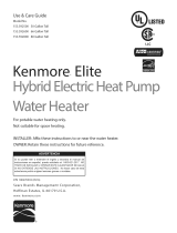
* Wiring size based on standard 60°C copper wire. If distance from fuse box to water heater is more than 90 feet, refer to your local electrical code.
MAXIMUM FUSE
RECOVERY RATE MINIMUM OR CIRCUIT
MODEL GALS.PER HOUR WIRE SIZE* BREAKER
NUMBER Gals Liters DIA. HEIGHT @90
0
F Rise UPPER LOWER (GAUGE) SIZE (AMPS)
153.582400 40 151 20.0 (508) 60.25 (1530) 25 5500 5500 10 30
ELEMENT
WATTAGE
@240 VOLTS
DIMENSIONS
IN INCHES (mm)
TANK
CAPACITY
PRODUCT SPECIFICATIONS
153.582500
50 189 22.0 (559) 60.50 (1537) 25 5500 5500
10
30

7
Basic Tools
You may or may not need all of these tools, depending on your
type of installation. These tools can be purchased at your local
Sears store.
Pipe Wrench (2)
Screwdriver
6 Foot Tape or Folding Rule
Garden Hose
Drill
Pipe Dope or Thread Sealing Tape
MATERIALS AND BASIC TOOLS NEEDED
SLOT-HEAD SCREWDRIVER
PHILLIPS SCREWDRIVER
DRILL
PIPE DOPE (SQUEEZE TUBE)
USE FOR WATER CONNECTIONS
ROLL OF THREAD SEALING TAPE
(USE ON WATER CONNECTIONS)
PIPE WRENCHGARDEN HOSE 6 FOOT TAPE
MINIMUM
HACKSAW
TUBING CUTTER
PROPANE
TORCH
ROLL OF
EMERY CLOTH
3/4” (19 mm) WIRE BRUSH
1/2” (13 mm) WIRE BRUSH
ROLL OF
LEAD-FREE
SOFT SOLDER
SOLDER
FLUX
Materials Needed
To simplify the installation Sears has available the installation parts shown below. You may or may not need all of these materials,
depending on your type of installation.
EXPANSION TANKS FOR THERMAL
EXPANSION CONDITIONS AVAILABLE IN
2 GALLONS , AND 5 GALLONS CAPACITY
THROUGH LOCAL SEARS STORE OR
SERVICE CENTER.
SUITABLE DRAIN PANS
AVAILABLE IN 20” DIAMETER
FOR WATER HEATERS HAVING
A DIAMETER 18” OR LESS AND
IN 24” DIAMETER FOR WATER
HEATERS HAVING A DIAMETER
OF 22” OR LESS.
WATER HEATER INSTALLATION KIT
WITH FLEXIBLE CONNECTORS FOR 3/4”
THREADED OR COPPER PLUMBING.
Additional Tools Needed When Sweat Soldering
Tubing Cutters or Hacksaw
Propane Torch
Soft Solder
Solder Flux
Emery Cloth
Wire Brushes

8
Removing the Old Water Heater
1. Turn “OFF” electrical supply to the water heater.
FIGURE 1
2. Open a nearby hot water faucet until the water is no longer
hot. When the water has cooled, turn “OFF” the water supply
to the water heater at the water shut-off valve or water meter.
FIGURE 2
3. Attach a hose to the water heater drain valve and put the
other end in a fl oor drain or outdoors. Open the water drain
valve. Open a nearby hot water faucet, which will relieve
pressure in the water heater and speed draining.
FIGURE 3
The water passing out of the drain valve may be extremely hot.
To avoid being scalded, make sure all connections are tight and
that the water fl ow is directed away from any person.
4. Check again to make sure the electrical supply is turned
“OFF” to the water heater. Next, unplug the water heater
(cord set) or disconnect the electrical supply connection from
the water heater junction box.
FIGURE 4
5a. If you have copper piping to the water heater, the two
copper water pipes can be cut with a hacksaw approximately
four inches away from where they connect to the water
heater. This will avoid cutting off the pipes too short.
Additional cuts can be made later if necessary. Disconnect
the temperature-pressure relief valve drain line. When
the water heater is drained, disconnect the hose from the
drain valve. Close the drain valve. The water heater is now
completely disconnected and ready to be removed.
FIGURE 5
5b. If you have galvanized pipe to the water heater, loosen the
two galvanized pipes with a pipe wrench at the union in each
line. Also disconnect the piping remaining to the water heater.
These pieces should be saved since they may be needed
when reconnecting the new water heater. Disconnect the
temperature-pressure relief valve drain line. When the water
heater is drained, disconnect the hose from the drain valve.
Close the drain valve. The water heater is now completely
disconnected and ready to be removed.
FIGURE 6
INSTALLATION INSTRUCTIONS

9
Mineral buildup or sediment may have accumulated in the old
water heater. This causes the water heater to be much heavier than
normal and this residue, if spilled out, could cause staining.
Facts to Consider About the Location
You should carefully choose an indoor location for the new water
heater, because the placement is a very important consideration
for the safety of the occupants in the building and for the most
economical use of the appliance. This water heater is not
intended for outdoor installation.
Whether replacing an old water heater or putting the water
heater in a new location, the following critical points must be
observed.
• The location selected should be indoors as close to and as
centralized with the water piping system as possible. This
water heater, as well as all water heaters, will eventually leak.
Do not install without adequate drainage provisions so water
fl ow will not cause damage.
WATER HEATERS EVENTUALLY LEAK: Installation of the water
heater must be accomplished in such a manner that if the tank
or any connections should leak, the fl ow of water will not cause
damage to the structure. When such locations cannot be avoided,
a suitable drain pan should be installed under the water heater.
Drain pans are available at your local Sears stores. Such drain
pans must be piped to an adequate drain.
Water heater life depends upon water quality, water pressure
and the environment in which the water heater is installed. Water
heaters are sometimes installed in locations where leakage may
result in property damage, even with the use of a drain pan piped
to a drain. However, unanticipated damage can be reduced or
prevented by a leak detector or water shut-off device used in
conjunction with a piped drain pan. These devices are available
from some plumbing supply wholesalers and retailers, and detect
and react to leakage in various ways:
• Sensors mounted in the drain pan that trigger an alarm or
turn off the incoming water to the water heater when leakage
is detected.
• Sensors mounted in the drain pan that turn off the water supply
to the entire home when water is detected in the drain pan.
• Water supply shut-off devices that activate based on the water
pressure differential between the cold water and hot water pipes
connected to the water heater.
INSTALLATION IN RESIDENTIAL GARAGES: The water heater
must be located and/or protected so it is not subject to physical
damage by a moving vehicle.
• The location selection must provide adequate clearances
for servicing and proper operation of the water heater.
Wiring
Electric Shock Hazard
Disconnect power before
servicing.
Replace all parts and panels
before operating.
Failure to do so can result in
death or electric shock.
WARNING
Fire Hazard
Use 10 gauge solid copper wire.
Use a UL approved strain relief.
Connect ground wire to green
ground screw.
Failure to do so can result in
death, fire, or electrical shock.
WARNING
If you lack the necessary skills required to properly install the
electrical wiring to this water heater, do not proceed, but have a
qualifi ed electrician perform the installation.
When making the electrical connections, always make sure:
• The electrical supply has the proper overload fuse or circuit
breaker protection.
• Wire sizes and connections comply with all applicable
codes.
• Wiring is enclosed in approved conduit (if required by local
codes).

10
• The water heater and electrical supply are properly
grounded.
• Always reference the wiring diagram for the correct electrical
connection. The complete wiring diagram can also be found
on the top of the water heater near the junction box cover.
• Although this water heater is equipped with “Dry-fi re”
protection, be sure the tank is completely fi lled with
water, and all air is purged from the tank before
making any electrical connections. See Figure 7.
NOTE: Applying electrical power to elements that are not submerged
in water will destroy them. The manufacturer will not warrant any
elements damaged in this manner.
Heating Element
Bang
FIGURE 7
1. Check and turn off power to the electrical wiring of the
water heater before making any electrical connections to
the water heater.
2. Remove the junction box cover that is secured by one screw
(Figure 9). Place the cover and screw aside and view the
wiring diagram. Locate the four power wires inside the
junction box (there will be TWO red wires and TWO black
wires).
3. Connect the electrical supply to the water heater in
accordance with the local utility requirements and codes. A
standard 1/2 inch opening has been made in the junction
box for the conduit connections (Figure 9). NOTE: Use only
10 gauge solid copper wire for the electrical connections and
an appropriately-sized double pole circuit breaker.
Fire Hazard
Use 10 gauge solid copper wire.
Use a UL approved strain relief.
Connect ground wire to green
ground screw.
Failure to do so can result in
death, fire, or electrical shock.
WARNING
4. Ground the water heater by connecting the bare copper ground
wire from the home’s electrical service to the green ground
screw (located inside the electrical junction box on top of the
water heater). See Figure 8 and Figure 9.
5. There are TWO black wires and TWO red wires in the water
heater. The smaller red and black wires are used by the
Kenmore Smart accessory port.
6. Connect the black power wire from the home’s electrical
service to the heater’s TWO black wires and secure with the
appropriate size wire nut. When you are fi nished, you will have
THREE black wires under one wire nut.
7. Locate and connect the remaining power wire (usually
red, but in your home, this wire may be some other
color) from the home’s electrical service to the water heater’s
TWO red wires and secure with the appropriate size wire nut.
When you are fi nished, you will have THREE red wires under
one wire nut (depending on the actual color of your home’s
electric wiring).
Wiring Diagram
Circuit
Breaker
L1
L2
To 240v
1 Phase
Power
supply
Electrical
Service ground
Ring Terminal
at Ground
Screw
Red
Black
Approved
Connectors
Water Heater
Kenmore Smart
Accessory Port
Black
Red
Green
FIGURE 8
Junction Box
Junction Box Cover
Red Wires
(3)
Black Wires
(3)
Ground Wires
(Ground Screw is
Under the Cover)
Kenmore Smart
Port Cover
1/2” Conduit
Connection
From Home
Electrical Service
FIGURE 9
Energy Saver
Module (ESM)
Electronic Thermostat (ET)
Electronic
Thermostat (ET)
Wiring Harness
( Junction Box )
Wiring Harness
( ET to ESM )
FIGURE 10

11
Water supply pressure should be around 50 to 60 psi and should
not exceed 80 psi. If this occurs, a pressure reducing valve
should be installed in the cold water inlet line. This should be
placed on the supply to the entire house in order to maintain
equal hot and cold water pressures.
IMPORTANT: Heat cannot be applied to the water fi ttings on the
heater as they may contain nonmetallic parts. If solder connec-
tions are used, solder the pipe to the adapter before attaching the
adapter to the hot and cold water fi ttings.
IMPORTANT: Always use a good grade of joint compound and
be certain that all fi ttings are drawn up tight.
1. Install the water piping and fi tting as shown in
Figure 11. Connect the cold water supply (3/4” NPT)
to the fi tting marked “Cold”. Connect the hot water
supply (3/4” NPT) to the fi tting marked “Hot”.
IMPORTANT: Some models may contain energy saving
heat
traps to prevent the circulation of hot water within the pipes.
Do not remove these inserts.
2. The Installation of dielectric unions in both the hot
and cold water supply lines is recommended for
ease of removing the water heater for service or
replacement.
3.
Install thermostatic mixing valves (temperature limiting
valves) at each point of use (recommended).
These valves
reduce the point-of-use temperature of the hot water by
mixing cold and hot water and are readily available. Contact
a licensed plumber or the local plumbing authority.
4. If installing the water heater in a closed water
system, install a relief valve or expansion tank in
the cold water line as specifi ed under “Closed
System/Thermal Expansion”.
5. Install a shut-off valve in the cold water inlet line. It
should be located close to the water heater and be
easily accessible. Know the location of this valve
and how to shut off the water to the heater.
Water Piping
HOTTER WATER CAN SCALD: Water heaters are intended to
produce hot water. Water heated to a temperature which will satisfy
clothes washing, dish washing, and other sanitizing needs can
scald and permanently injure you upon contact. Some people are
more likely to be permanently injured by hot water than others.
These include the elderly, children, the infi rm, or physically/
mentally challenged. If anyone using hot water in your home
fi ts into one of these groups or if there is a local code or state
law requiring a certain temperature water at the hot water tap,
then you must take special precautions. Use the lowest possible
temperature setting that satisfi es your hot water needs. Also, to
reduce the risk of scalding, the manufacturer of this water heater
recommends installing a mixing valve at each point of use. Mixing
valves are available at plumbing supply or hardware stores. Follow
the manufacturer’s instructions for installation of the valves.
Before changing the factory setting on the thermostat, read the
“Temperature Regulation” section in this manual.
Piping, fi ttings, and valves should be installed according to the
installation drawing (Figure 11). If the indoor installation area
is subject to freezing temperatures, the water piping must be
protected by insulation.
FIGURE 11

12
6. Install a discharge line from the temperature and
pressure relief valve in the opening marked “T & P
RELIEF VALVE”. Install as specifi ed under
“Temperature and Pressure Relief Valve”.
7. After piping has been properly connected to the
water heater, open the nearest hot water faucet.
Then open the cold water shut off valve and
allow the tank to completely fi ll with water. To purge
the lines of any excess air and sediment, keep the
hot water faucet open for 3 minutes after a constant
fl ow of water is obtained. Close the faucet and
check all connections for leaks.
Please note the following:
• DO NOT install this water heater with iron piping.
The system should be installed only with piping that
is suitable for potable (drinkable) water such as
copper, CPVC, or polyethylene (PEX).
• DO NOT use PVC water piping.
• DO NOT use any pumps, valves, or fi ttings that are
not compatible with potable water.
• DO NOT use valves that may cause excessive
• restriction to water fl ow. Use full-fl ow ball or gate valves only.
• DO NOT use tin-lead solder in potable water lines.
Use 95/5 tin antimony or other equivalent material.
• DO NOT tamper with the Energy Saver Module (ESM),
electronic thermostat, temperature sensors, heating
elements, electrical connections, or temperature and
pressure relief valve. Tampering voids all warranties.
Only qualifi ed service technicians should service these
components.
• DO NOT use with piping that has been treated with
chromates, boiler seal, or other chemicals.
• DO NOT add any chemicals to the system piping which will
contaminate the potable water supply.
Temperature-Pressure Relief Valve
Explosion Harzard
7HPSHUDWXUHSUHVVXUHUHOLHI
YDOYHPXVWFRPSO\ZLWK$16,
=&6$DQG$60(
FRGH
3URSHUO\VL]HGWHPSHUDWXUH-
SUHVVXUHUHOLHIYDOYHPXVWEH
LQVWDOOHGLQRSHQLQJSURYLGHG
'RQRWSOXJEORFNRUFDSWKH
GLVFKDUJHOLQH
)DLOXUHWRIROORZWKLVZDUQLQJ
FDQUHVXOWLQH[FHVVLYHWDQN
SUHVVXUHVHULRXVLQMXU\RU
GHDWK
This heater is provided with a properly certifi ed combination
temperature - pressure relief valve by the manufacturer.
The valve is certifi ed by a nationally recognized testing laboratory
that maintains periodic inspection of production of listed
equipment of materials as meeting the requirements for Relief
Valves for Hot Water Supply Systems, ANSI Z21.22 • CSA 4.4,
and the code requirements of ASME.
If replaced, the valve must meet the requirements of local codes,
but not less than a combination temperature and pressure relief
valve certifi ed as indicated in the above paragraph.
The valve must be marked with a maximum set pressure not to
exceed the marked hydrostatic working pressure of the water
heater (150 psi = 1,035 kPa) and a discharge capacity not less
than the water heater input rate as shown on the model rating
plate. (For electric heaters, watts x 3.412 equals Btu/hr input rate).
For safe operation of the water heater, the relief valve must not
be removed from its designated opening nor plugged.
The temperature-pressure relief valve must be installed directly
into the fi tting of the water heater designed for the relief valve.
Position the valve opening downward and provide tubing so
that any discharge will exit only within 6 inches above, or at any
distance below the structural fl oor. Be certain that no contact is
made with any live electrical part. The discharge opening must not
be blocked or reduced in size under any circumstances. Excessive
length, over 30 feet (9.14 m), or use of more than four elbows can
cause restriction and reduce the discharge capacity of the valve.
No valve or other obstruction is to be placed between the
relief valve and the tank. Do not connect tubing directly to
discharge drain unless a 6 inch air gap is provided. To prevent

13
Filling the Water Heater
Never use this water heater unless it is completely full of water.
To prevent damage to the tank and heating element, the tank
must be fi lled with water. Water must fl ow from the hot water
faucet before turning “ON” power.
To fi ll the water heater with water:
1. Close the water heater drain valve by turning the handle to
the right (clockwise). The drain valve is located on the lower
front of the water heater.
2. Open the cold water supply valve to the water heater.
NOTE: The cold water supply valve must be left open when
the water heater is in use.
3. To ensure complete fi lling of the tank, allow air to exit by
opening the nearest hot water faucet. Allow water to run until
a constant fl ow is obtained. This will let air out of the water
heater and the piping.
4. Check all new water piping for leaks. Repair as needed.
bodily injury, hazard to life, or property damage, the relief
valve must be allowed to discharge water in quantities should
circumstances demand. If the discharge pipe is not connected
to a drain or other suitable means, the water fl ow may cause
property damage.
The Discharge Pipe:
• Must not be smaller in size than the outlet pipe size of the valve,
or have any reducing couplings or other restrictions.
• Must not be plugged or blocked.
• Must be of material listed for hot water distribution.
• Must be installed so as to allow complete drainage of both the
temperature-pressure relief valve, and the discharge pipe.
• Must terminate a maximum of six inches above a fl oor drain
or external to the building. In cold climates, it is recommended
that the discharge pipe be terminated at an adequate drain
inside the building.
• Must terminate at an adequate drain.
• Must not have any shut-off valve between the relief valve and
tank nor in the discharge pipe.
See also “Temperature-Pressure Relief Valve Operation” on
page 20.

14
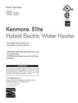
Wiring Diagram
120
V
1500*
2000
2500
3000
3500
4000
4500
5000
5500
15
20
30
30
-
-
-
-
-
WATT
LOAD
BRANCH CIRCUIT SIZING GUIDE
Based on N.E.C. NFPA NO. 70 - 1999
15
15
15
20
20
25
30
30
15
15
15
15
20
20
25
30
30
208
V
240
V
Recommend
Over Current
Protection Rating
12
10
10
8
-
-
-
-
-
14
14
14
12
10
10
10
10
14
14
14
12
12
10
10
10
10
120
V
208
V
240
V
Copper Wire Size
AWG Based on
N.E.C.
Table 310 - 16
C)
Wattages less than 1500 may be wired 14 gage with a maximum
15 amp protection.
ELECTRONIC
THERMOSTAT (ET)
FUSED DISCONNECT
OR CIRCUIT BREAKER
L 1
L 3
L 4
T 4
T 2
TEMPERATURE
SENSOR
UPPER
ELEMENT
LOWER
ELEMENT
ENERGY SAVER
MODULE (ESM)
GROUND
SCREW
ELECTRICAL
SERVICE
GROUND
RED
BLACK
YELLOW
RED
BLACK
BLUE
ON
JUNCTION
BOX COVER
BLACK - 5 WIRES
BLACK - 2 WIRES
KENMORE SMART
ACCESSORY
PORT
GREEN
BLACK
RED
BLACK - 4 WIRES
FIGURE 12

15
Installation Checklist
WATER HEATER LOCATION:
□ Centrally located with the water piping system.
□ The fl ooring beneath the water heater must be able to
support the weight of the water heater when fi lled with water.
□ Located indoors and in a vertical position. Protected from
freezing temperatures.
□ Provisions made to protect the area from water damage.
Suitable drain pan installed and piped to an adequate drain.
□ Suffi cient room to service the water heater.
□ The site location must be free from any corrosive elements
in the atmosphere such as sulfur, fl uorine, and chlorine.
These elements are found in aerosol sprays, detergents,
bleaches, cleaning solvents, air fresheners, paint, and
varnish removers, refrigerants, and many other commercial
and household products.
WATER SYSTEM PIPING
□ Temperature and pressure relief valve properly installed with
a discharge pipe run to an adequate drain and protected
from freezing. See Figure 11 on page 11.
□ All piping properly installed and free of leaks.
□ Suitable drain pan lines installed and piped to an adequate
drain. See Figure 11 on page 11.
□ Heater completely fi lled with water.
□ Closed system pressure buildup precautions installed (See
“Closed System/Thermal Expansion” section).
□ Mixing valves recommended, installed per manufacturer’s
instructions at each point of use.
ELECTRICAL CONNECTIONS
□ Wiring and connections comply with all applicable codes.
□ Water heater and electrical supply are properly grounded.
□ Proper overload fuse or circuit breaker protection installed.

16
KENMORE
®
SMART WATER HEATER MODULE
This water heater is a connected-ready appliance, allowing you
to remotely monitor and control it from your smartphone via the
Kenmore
®
Smart Water Heater Module, which is sold separately.
To get started, you will need the following:
• Kenmore Smart Water Heater Module
• WI-FI home router connected to the internet
• Smartphone
• Kenmore Smart app
For more information about the Kenmore® Smart Water Heater
Module, visit www.Kenmore.com/smart.

17
OPERATING YOUR WATER HEATER
Water Heater Start-Up
1. Carefully read and understand “Water Temperature Regulation.”
If the instructions are not clear, contact a qualifi ed service
technician.
2. Make sure the water heater has been properly installed. See
the “Installation Instructions” section.
3. Completely fi ll the tank with water; open faucet to allow air
to purge. (See page 13.)
4. After the tank is completely fi lled with water, turn on power to
the water heater at the breaker panel.
5. Power to the water heater will allow the water heater to run
a system diagnostic. This typically takes eight minutes. Once
complete, proceed to the next step. NOTE: if the system
diagnostic yields any codes, reference the Diagnostic Code
section in this manual.
6. Adjust the thermostat to the desired temperature setting
as described under “Adjusting the User Interface Module/
Operational Modes” section.
IMPORTANT: Operation of this water heater without
access doors or insulation could result in much higher
water temperatures than the desired set point,
increasing the risk of scald injury.
Do not operate water heater with
the access doors or insulation
removed.
ACCESS DOORS
GRID
ENABLED
VACATION
STANDARD
ENERGY
SMART
°F/°C
F
FIGURE 13
IMPORTANT: Do not attempt to operate this water heater if the
temperature sensor(s), electronic control board, or surrounding
insulation has been exposed to water in any way. Immediately
call a qualifi ed service technician to inspect the water heater and
replace any temperature sensor(s), electronic control board, or
insulation that has been exposed to water. Do not attempt to
repair these parts. Water heaters subjected to fl ood conditions
or any time the temperature sensor(s) or electronic thermostat
have been submerged in water require replacement of the entire
water heater.
Safety Shut-Off
This water heater is designed to automatically shut-off in the
event that the water temperature exceeds 180° F (82.2° C). A
temperature limit switch, or ECO (Energy Cut Off), is used to shut
off the power to the system if the water temperature exceeds
180° F or 82.2° C. The ECO can be reset by fi rmly pushing in
the red reset button located on the electronic thermostat. (See
Figure 15 on page 19.) If the ECO continues to shut-off the
water heater contact a qualifi ed service technician.
Water Temperature Regulation
The water heater is adjusted to a temperature setting of no higher
than 120° F when shipped from the factory. Water temperature can
be regulated by adjusting the Energy Saver Module to the preferred
setting as shown in “Modes and Adjustments.” The preferred starting
point is 120° F. There is a hot water scald potential if the temperature
set point is set too high.
IMPORTANT: Adjusting the temperature past 120° F on the Energy
Saver Module will increase the risk of scald injury in the times
shown below. To reduce the risk of scalding, install thermostatic
mixing valves (temperature limiting valves) at each point of use
(recommended).
Water
Temperature
°F (°C)
Time for 1st
Degree Burn
(Less Severe Burns)
Time for Permanent Burns
2nd & 3rd Degree
(Most Severe Burns)
110°F (43°C)
(normal shower temp.)
116°F (47°C)
(pain threshold)
116°F (47°C)
35 minutes 45 minutes
122°F (50°C)
1 minute 5 minutes
131°F (55°C)
5 seconds 25 seconds
140°F (60°C)
2 seconds 5 seconds
149°F (65°C)
1 second 2 seconds
154°F (68°C)
instantaneous 1 second
(U.S. Government Memorandum, C.P.S.C., Peter L. Armstrong, Sept. 15,1978)
When leaving your home for extended periods (vacations, etc.)
set the water heater to Vacation Mode. This will maintain the
water at low temperatures with minimum energy losses and
prevent the tank from freezing during cold weather. See the
“Modes and Adjustments” section for more information.
NOTE: When returning from an extended stay, remember to set
the water heater back to the desired Operational Mode.

18
Modes and Adjustments
WATER TEMPERATURE ADJUSTMENT
IMPORTANT: Before attempting to adjust the thermostat, read
the “Water Temperature Regulation” section. If the instructions
are not clear, contact a qualifi ed service technician.
The water temperature can be adjusted from 80° F to 150°
F. Use the Up and Down Buttons
to set the desired
temperature.
OPERATING MODE DESCRIPTIONS
The operating modes can be changed by touching the desired
mode icon on the Energy Saver Module. (See below.)
NOTE: All buttons on the Energy Saver Module are touch
sensitive and require only a light touch to actuate.
FIGURE 14
ENERGY SAVER - Pressing this button
switches to the Energy Saver operating
mode. This will reduce energy consumption
by adjusting the temperature set point
automatically to match water usage
patterns. (Temperature set point can still
be changed.)
STANDARD - Pressing this button will
switch operation to Standard operating
mode. The water heater will not adjust its
temperature set point automatically; it will
maintain the programmed temperature set
point (like a standard electric water heater).
VACATION MODE - The Energy Saver
control adjusts the set point to approximately
60°F, which is recommended when the
water heater will not be in use for a long
period of time. This mode minimizes energy
consumption and prevents the water heater
from freezing during cold weather. NOTE:
If your water heater is in Vacation Mode,
you can return it to its previous settings by
pressing the Vacation Mode button again.
REMOTE ACCESS - Pressing this button
will enable or disable remote monitoring and
control through an optional Kenmore Smart
Water Heater Module. See page 16.
ENTER / LOCK - Pressing this button once
after a user setting has been changed
confirms and saves the new setting.
Holding this button for more than 3 seconds
switches the lock mode on or off. When the
User Module is locked, a symbol and “Lock”
text will be visible on the display.
°F/°C - Pressing this button switches the
display to show the set temperature in
Fahrenheit or Celsius.
Fault condition will display an “E,” followed
by a two digit fault code (with Alert Icon
fl ashing). See diagnostic code chart on
page 26.
Element Functioning Icon - indicates power
is on at either upper or lower element
circuits and both are working properly.
°F/°C
°F/°C
F
REMOTE
ACCESS
VACATION
STANDARD
ENERGY
SAVER
CONTROL PANEL
LOCK ICON
OPERATIONAL
MODE BUTTONS
ELEMENT
FUNCTIONING
ICON
WATER
TEMPERATURE
SET POINT
TEMPERATURE
DOWN (DECREASE)
BUTTON
TEMPERATURE
UP (INCREASE)
BUTTON
FAHRENHEIT/
CELSIUS
TEMPERATURE
DISPLAY
BUTTON
ENERGY SAVER
MODULE (ESM)
ENERGY SAVER MODULE (ESM)
LOCK
ELEMENT
ALERT
LCD DISPLAY PANEL
LOCK BUTTON
ELECTRONIC
THERMOSTAT
(ET)
ENTER
ELEMENT
NOTE: THE ELECTRONIC THERMOSTAT (ET) IS DESIGNED
SO THAT IT MAY CONTROL THE WATER HEATER WITHOUT
THE ENERGY SAVER MODULE (ESM) BEING OPERATED.
SEE PAGE 19.
ENTE R

19
The Electronic Thermostat
IMPORTANT: The Energy Saver Module (ESM) must be removed
before attempting to access the thermostat. NOTE: For the
Electronic Thermostat (ET) changes to remain in effect, the
Energy Saver Module (ESM) must not be reconnected. Also,
read the “Water Temperature Regulation” under the “Operating
Your Water Heater” section. If the instructions are not clear,
contact a qualifi ed service technician.
The Energy Saver Module (ESM) is intended to serve as the
primary interface for operating the water heater; however, the
Electronic Thermostat (ET) may control the water heater in the
absence of the Energy Saver Module (ESM).
The Electronic Thermostat consists of an electronics box
that contains a low voltage power supply, the thermostat set
point knob, relays to switch between the upper and lower
heating elements, one control thermistor, a connector for the
lower element control thermistor, microelectronics to convert
the thermistor signals and perform switching and other logic
functions, and a connector to tie the Electronic Thermostat (ET) to
the Energy Saver Module (ESM) located on the front of the water
heater jacket. The majority of the self-diagnostics are located in
the Electronic Thermostat (ET), including the dry-fi re protection
intelligence. The thermostat circuit is designed so that when the
upper heating element calls for heat, the power is directed to
that element even if the lower element is also calling for heat.
Diagnostic LED Light
The Green/Red LED light indicates the status of the electronic
thermostat (Figure 15).
• Green LED will signal normal operation. The green LED will
blink 2 times per second to indicate that power is applied to
the upper heating element and at a faster rate (4 times per
second) to indicate that the lower heating element is powered.
• Red LED will fl ash error codes. If a fault is detected by the
electronic thermostat, the LED light indicator will use the red
LED to indicate the fault detected. The fl ash code sequence
is to consist of 1/2 second fl ashes of the red LED each
separated by a 1/2 second off period.
The number of fl ashes indicates the fault code number. (See
diagnostic code chart section in this manual).
After the last 1/2 second “on” period, the LED will remain off
until a total of 5 seconds has elapsed for the fault indication
cycle (there is a 5 seconds delay before the fault fl ash pattern
repeats). After the 5 seconds are completed, the fault indication
cycle is repeated starting with the fi rst 1/2 second-fl ash. The
fl ash sequence will be repeated as long as the fault remains.
Only one fault can be declared at a time. NOTE: the green LED
is turned off when a fault code is being displayed, even though
the heater may be operating in limp mode with an element on.
See diagnostic code chart section in this manual.
Overriding The Energy Saver Module (ESM)
If the Energy Saver Module (ESM) is not working, simply unplug
the interface module and turn the set point knob on the Electronic
Thermostat (ET) to the desired temperature (See Figure 15 and
Figure 16). To replace a broken or damaged ESM module, see
page 32 for ordering information.
ELECTRONIC THERMOSTAT (ET)
DIAGNOSTIC
LED LIGHT
ECO RESET
BUTTON
SETPOINT
KNOB
PLASTIC GUARD
UPPER
ELEMENT
REMOVE ONLY AFTER POWER IS TURNED OFF
(WHEN REPLACING ELEMENT)
ENERGY SAVER
MODULE (ESM)
ELECTRONIC THERMOSTAT (ET)
ELECTRONIC
THERMOSTAT (ET)
THERMOSTAT
SETPOINT KNOB
JUNCTION BOX
WIRING HARNESS
THERMISTOR
WIRE HARNESS
NOTE: Remote Access will be disabled when the Energy Saver
Module (ESM) is disconnected from the junction box wiring
harness.
Electrical Shock Hazard
Do not remove the plastic
guard from over wiring.
Do not touch electrical wiring.
Failure to do so can result in
death or electrical shock.
FIGURE 15
FIGURE 16

20
SERVICE AND ADJUSTMENT
If you lack the necessary skills required to service this water
heater properly, or if you have diffi culty following the instructions,
you should not proceed. Have a qualifi ed service technician
perform the maintenance of this water heater.
Anode Rod Inspection
See also “Smelly Water” on page 23.
Each water heater contains at least one anode rod, which will
slowly deplete (due to electrolysis), prolonging the life of the
water heater by protecting the glass-lined tank from corrosion.
Adverse water quality, hotter water temperatures, high hot water
usage, hydronic heating devices, and water softening methods
can increase the rate of anode rod depletion. Once the anode rod
is depleted, the tank will start to corrode, eventually developing
a leak.
Certain water conditions will cause a reaction between the anode
rod and the water. The most common complaint associated with
the anode rod is a “rotten egg smell” produced from the presence
of hydrogen sulfi de gas dissolved in the water. CAUTION: Do
not remove this rod permanently as it will void any warranties. A
special anode rod may be available if water odor or discoloration
occurs. NOTE: this rod may reduce but not eliminate water odor
problems. The water supply system may require special fi ltration
equipment from a water conditioning company to successfully
eliminate all water odor problems.
Artifi cially softened water is exceedingly corrosive because the
process substitutes sodium ions for magnesium and calcium ions.
The anode rod should be inspected after a maximum of three
years and annually thereafter until the condition of the anode
rod dictates its replacement. NOTE: Artifi cially softened water
requires the anode rod to be inspected annually.
The following are typical (but not all) signs of a depleted anode
rod:
• The majority of the rods diameter is less than 3/8”.
• Signifi cant sections of the support wire (approx. 1/3 or
more of the anode rod’s length) are visible.
If the anode rod shows signs of either or both it should be
replaced (Figure 17). NOTE: Whether re-installing or replacing
the anode rod, check for any leaks and immediately correct if
found.
FIGURE 17
Follow these steps to replace the anode:
1. Turn off power to the water heater.
2. Shut off the water supply and open a nearby hot water
faucet to depressurize the water tank.
3. Drain approximately 5 gallons of water from tank. (Refer to
“Draining and Flushing” for proper procedures). Close drain
valve.
4. Remove old anode rod.
5. Use Tefl on
®
tape or approved pipe sealant on threads and
install new anode rod.
6. Turn on water supply and open a nearby hot water faucet
to purge air from water system. Check for any leaks and
immediately correct any if found.
7. Restart the water heater as directed in this manual.
NOTE: The water heater will conduct a system diagnostic
prior to operation. See the Repair Parts Illustration for anode
rod location.
Tefl on
®
is a registered trade mark of Chemours.
Temperature-Pressure Relief Valve Operation
The temperature-pressure relief valve must be manually operated
at least once a year.
The temperature-pressure relief valve must be manually operated
at least once a year. Caution should be taken to ensure that
(1) no one is in front of or around the outlet of the temperature-
pressure relief valve discharge line, and (2) the water manually
discharged will not cause any property damage or bodily injury.
The water may be extremely hot.
/