
PRODUCED IN CHINA FOR:
GB
IE
Great care has gone into the manufacture of this product and it should
therefore provide you with years of good service when used properly. In
the event of product failure within its intended use over the course of the
first 3 years after date of purchase, we will remedy the problem as quickly
as possible once it has been brought to our attention. In the unlikely event
of such an occurrence, or if you require any information about the product,
please contact us via our helpline support services, details of which are to be
found both in this manual and on the product itself.
ALDI STORES LTD. PO BOX 26, ATHERSTONE
WARWICKSHIRE, CV9 2SH.
ALDI STORES (IRELAND) LTD.
PO BOX 726, NAAS, CO. KILDARE.
Visit us at www.aldi.com
AFTER SALES SUPPORT
800103
GB IE
MODEL:
GRHS20A
04/2020
+44(0) 1904727501
+353(0) 019022605
3
YEAR
WARRANTY
User Manual
HOSE REEL
Original User Manual

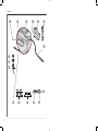
Overview
2
1
2
3
5
6
7
8
9
10
11
12
13
14
15
4

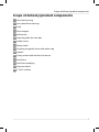
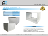
Scope of delivery/product components
1
Hose box housing
2
Carry handle on housing
3
Flap
4
Hose stopper
5
Wall mount
6
Mounting bolts for hose box
7
Garden hose
8
Spray nozzle
9
Coupling for garden hose with water stop
10
Dowels
11
Fixing screws with washers for mount
12
Feed hose
13
Feed hose coupling
14
Tap connection
15
1" to ¾" reducer
Scope of delivery/product components
3


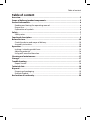
Table of content
Overview..................................................................................................................2
Scope of delivery/product components.................................................................3
General information................................................................................................6
Reading and storing the operating manual..................................................................6
Proper use...........................................................................................................................6
Explanation of symbols.....................................................................................................6
Safety....................................................................................................................... 7
Safety notes.........................................................................................................................7
Functional description............................................................................................ 9
Before first use.......................................................................................................10
Check the device and scope of delivery........................................................................10
Assembly instruction....................................................................................................... 10
Operation............................................................................................................... 15
Locking / unlocking outlet hose.....................................................................................15
Adjusting water jet...........................................................................................................16
Using wall-mounted hose box.......................................................................................16
Cleaning and maintenance....................................................................................17
Storage................................................................................................................... 17
Troubleshooting.....................................................................................................17
Repair Service................................................................................................................... 18
Technical data........................................................................................................ 18
Disposal.................................................................................................................. 19
Disposing of packaging...................................................................................................19
Product disposal...............................................................................................................19
Declaration of conformity..................................................................................... 20
Table of content
5

General information
Reading and storing the operating manual
This operating manual is a part of the Wall-mounted Hose Box (hereinafter
called "product"). It contains important information on how to set up and
use the product.
Read the user manual carefully, in particular the safety instructions, before
using the product. Failure to follow this user manual may lead to severe injuries or
product damage.
This user manual is based on the standards and regulations that are valid within the
European Union. Outside the EU, please also note the country-specific directives and
laws.
Keep this user manual for future reference. If you pass this product on to a third
party, you must also supply this user manual.
Proper use
Wall-mounted Hose Box was exclusively designed as a hose drum in an enclosed
hose box with a reeling mechanism and a connection to the building's water supply.
Other systems that are operated with water (e.g. such as lawn sprinklers, irrigation
systems and high-pressure cleaners) can also be connected to the Wall-mounted
Hose Box.
The plastic dowels are designed for concrete walls.
The product is intended for private use only and is not suitable for commercial use.
Use the product only as described in this operating manual. Any other use is
improper and may lead to product damage or even personal injury. This product is
not a toy.
The manufacturer or retailer assumes no liability for damage caused by improper or
incorrect use.
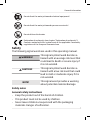
Explanation of symbols
The following symbols are used in this operating manual, on the product or on the
packaging.
This symbol provides you with useful additional information on
handling and use.
Read the operating manual.
General information
6

Do not direct the water jet towards electrical equipment!
Do not direct the water jet towards persons or animals!
Do not deliver drink water.
Declaration of conformity (see chapter “Declaration of conformity”):
Products marked with this symbol meet all the applicable Community
regulations of the European Economic Area.
Safety
The following signal words are used in this operating manual.
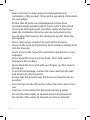
WARNING!
This signal symbol/word denotes a
hazard with an average risk level that
could lead to death or severe injury if
it is not avoided.
CAUTION!
This signal symbol/word denotes a
hazard with a low risk level that could
lead to mild or moderate injury if it is
not avoided.
NOTE!
This signal word provides a warning
about potential material damage.
Safety notes
General safety instructions
- Keep the product out of the hands of children.
- This product must not be used by children.
- Never leave children unsupervised with the packaging
materials. Danger of suffocation.
General information
7

- Make sure that no water pipes are damaged during
installation of the product. Observe the operating instructions
for your safety.
- Ensure that all parts are undamaged and have been
assembled appropriately. Risk of injury exists if assembled
incorrectly. Damaged parts can effect safety and function.
-
Have the installation done by experienced persons only.
-
Do not open the housing. The springs are preset; they may
spring back.
- Never remove any screws from parts of the housing.
-
Never let the hose spring back by itself. Guide it carefully back
into the housing.
- Never let go of the hose if the automatic stop function is not
engaged.
- Never allow the hose to retract freely. This could result in
damage to the product.
- Never block the hose end with your fingers or other objects
during use.
- To avoid frost damage, remove the hose reel from the wall
and store it dry during winter.
- Ensure that the ground near the hose reel is kept as dry as
possible.
- Turn the tap into the off position when the hose reel is not in
use.
- The hose is not suitable for delivering drinking water.
- Do not direct the water jet towards electrical equipment!
- Do not direct the water jet towards persons or animals!
Safety
8

WARNING!
Risk of injury!
Faulty operation due to improper handling may cause injuries.
This poses a risk to children and persons with reduced physical,
sensory or mental abilities (such as partially disabled or older
persons with restricted physical and mental abilities) or a lack of
experience and knowledge (such as older children).
- Children aged 8 years and older as well as persons with
reduced physical, sensory or mental abilities or a lack of
experience and knowledge may only use the product if they
are supervised or have been given instruction on using the
product in a safe way and understand the hazards involved.
-
Children under the age of 8 must not use the product.
- Children must not play with the product or the connection
cable.
- Cleaning or user maintenance must not be undertaken by
children unless supervised.
-
Do not leave the product unattended when in use.
- Do not let children play with the packaging film. They may
become tangled when playing and suffocate.
Functional description
The wall-mounted hose box is equipped with the heavy duty spring-loaded
mechanism to provide automatic slow rewinding and lock hose anywhere, and the
guide to prevent the hose from overlapping, knot and tangle.
The wall-mounted bracket allows the hose box to pivot 180°so the hose follows your
direction as you water. Included 20m hose makes watering easy and convenient in
your garden to save your time. When you are finished watering, simply pull the hose
and the reel automatically draws it back into the weather-resistant plastic housing.
Unit easily removes for storage indoors in winter season.
Safety
9

Before first use
Check the device and scope of delivery
NOTE!
Risk of damage!
If opening the packaging with a sharp knife or other pointed
object, be careful to avoid damaging the product’s surface.
- Proceed carefully with opening the packaging.
1. With both hands, lift the product out of the packaging.
2. Check that the delivery is complete (see chapter “Scope of delivery/device
components”).
3. Inspect the product and individual parts for damage. Do not operate a damaged
product, instead contact the manufacturer via the service centre listed on the
warranty card.
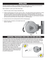
Assembly instruction
WARNING!
Danger of injury and suffocation!
Children or persons with disabilities may be injured if they install
the product.
- Do not let children or persons with disabilities perform the
installation.
- Keep children away from the installation site during
installation.
- Keep small parts and packaging materials away from
children. Children may swallow them and suffocate.
Before
first use
10

WARNING!
Danger of electric shock, short circuit and material damage
Power lines, water and gas pipes or other lines/pipes in the wall
may become damaged during the installation and lead to
hazards or damage to the environment.
- Make sure that you do not damage hidden pipes/lines during
the installation. Use suitable line/pipe detectors for this
purpose.
CAUTION!
Risk of injury!
If you do not precisely follow these assembly instructions,
mistakes may happen and lead to injuries.
- Only use the stated tools for the installation.
- Wear protective goggles when working with power tools and
always follow the manufacturer's instructions.
-
If you are not certain, have an experienced expert install the
product.
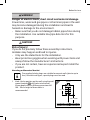
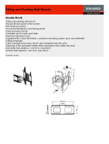
Mounting wallmounted bracket
The supplied plastic plugs are suitable for cement walls (plaster up to
1cm). For other wall types, special plugs must be used.
1. Mark 4 holes position on the wall using the wall
mount bracket 5 , drill holes into the wall
50mm depth with an Ø10mm percussion drill.
100 - 110 cm height of lower holes is
recommended.
3,3cm
12,1cm
100-110cm
1
Before
first use
11

Higher than 110cm will possible effect the auto rewind function.
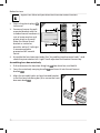
2. Stick in the plastic plugs 10
to the end.
3. Screw and secure the wall-
mounted bracket with the
included mount hardware (4
sets of screw, washer and
plastic plug) on the wall.
Make the central line of
bracket as vertical as
possible, within 5°left/right
is recommended to
guarantee 180°smooth
swivel.
4. Assemble the hose box main body (See “Assembling hosebox main body” ) and
check the pivot rotation left / right. Small adjustment of bracket if necessary.
Assembling hose box main body
1. Pull and remove the hose box fixing bar
6
from hose box, and hold it.
2. Carry the main body carrying handle 2 and insert it into the wall mount
bracket 5 .
3. Align the assembly holes on hose box and bracket,
insert the hose box fixing bar (3) to secure the hose
box main body 1 .
L5° R5°
2
3
Before
first use
12

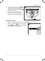
4. Swivel the hose box main body 1 left
and right to check the smoothness,
make sure the hose box main body 1
can stay any position.
5. Pull and return the outlet hose to
check the function of automatic slow
rewinding, hose locking and guiding.
Shifting hose stopper
1. Loosen the 2 crosshead screws on hose stopper
4 with a screwdriver
2. Hold the outlet hose 7 securely and shift the
stopper 4 to desired position, screw tightly
again with the 2 crosshead screws.
4
5
Before first use
13

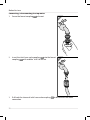
Connecting / disconnecting the tap water
1. Screw the faucet coupling 14 to faucet.
2. Insert the inlet hose male coupling 13 into the faucet
coupling
14
with audible “click” to secure.
1. Pull back the sleeve of inlet hose male coupling 13 to disconnect the water
connection.
6
7
Before
first use
14

Operation
NOTE!
Risk of damage!
- Always hold the hose tight when winding it up.
- Do not use the hose box in frosty weather.
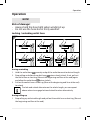
Locking / unlocking outlet hose
1
2
8
During unwinding
1. Hold the outlet hose 7 securely and pull the outlet hose out to desired length.
2. Stop pulling and allow the outlet hose 7 return slowly to lock. If not, pull out
the outlet hose a short tug (10cm at the beginning and 5cm at the end) again
and allow the outlet hose 7 return to lock.
3. Pull out the outlet hose a short tug (10cm at the beginning and 5cm at the end)
to unlock.
The lock and unlock alternates on the whole length, you can repeat
above actions to engage lock and unlock function alternatively.
During rolling up
1. Stop rolling up at desired length and pull out the outlet hose a short tug (10cm at
the beginning and 5cm at the end).
Operation
15

2. Allow the outlet hose 7 return slowly to lock. If not, pull out the outlet hose a
short tug (10cm at the beginning and 5cm at the end) again and allow the outlet
hose 7 return to lock
3. Pull out the outlet hose a short tug (10cm at the beginning and 5cm at the end)
to unlock.
The lock and unlock alternates on the whole length, you can repeat
above actions to engage lock and unlock function alternatively.
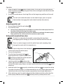
Adjusting water jet
1. Use one hand to hold the jet holder
8
.
2. Use another hand
a. to turn the jet adjustment bar clockwise to reduce the water spray from line
to splash, to the end to stop the water spray.
b. to turn the jet adjustment bar counter-clockwise to enlarge the water spray
from splash to line, to the end to the maximum water spray.
Using wall-mounted hose box
The built-in automatic hose guide is preventing the hose from
overlapping while rolling up. Do not use hand to settle the hose coil.
There is a water stopper inside the outlet hose male coupling, help
change the nozzle with the tap water on.
1. Turn the nozzle adjustment bar clockwise
to the end to stop the water spray.
2. Turn on the tap water.
3. Turn the hose box main body
1
to
working direction, hold the outlet hose
7
securely and pull the outlet hose out
to unwind to desired length.
4. Lock the outlet hose
7
and turn the
nozzle adjustment bar counter-clockwise
to start the water spray. Always use one hand to hold the nozzle holder
8
when
watering.
5. Hold the outlet hose
7
securely, unlock the outlet hose
7
to unwind or roll up
it to adjust the hose length. It’s recommended to turn the nozzle adjustment bar
clockwise to the end to stop the water spray before hose length adjustment.
6. After watering, turn the nozzle adjustment bar clockwise to the end to stop the
water spray, hold the outlet hose
7
securely to roll up slowly to the hose
9
Operation
16

stopper 4 . If certain length left outside the hose box main body 1 , pull out
the outlet hose 7 by 1-2m and roll up again. Do not push the hose back into the
hose box main body 1 .
7. Turn off the tap water and rotate the hose box main body 1 against the wall.
Cleaning and maintenance
Any work that is not described in these Instructions must be carried out by a
servicing agency authorized by us.
- Always keep the hose box main body 1 clean. Do not use cleaning agents and
solvents.
-
Always turn off the tap water when the wallmounted hose box is not in use
-
Use the water spray to clean the hose box main body
1
. Do not immerse the
wall-mounted hose box in water.
-
Remove the hose box main body 1 indoors in a frost period (See “Storage”).
-
Check the inlet hose
12
and outlet hose
7
carefully. Do not use the hose box if
any cut on them.
-
Check the seal O-ring on nozzle holder
8
and faucet coupling
14
.
-
Regularly check and clean the inside through the flap
3
.
-
Contact our service center if any problem.
Storage
1. Carefully clean the hose box main body
1
and its accessories.
2. Turn off the tap water and remove the inlet hose male coupling
13
from the
faucet coupling
14
.
3. Use one hand to grip the main body carrying handle
2
and another hand to
pull out the hose box fixing bar
6
.
4. Remove the hose box main body
1
from wall-mounted bracket
5
and insert
the hose box fixing bar
6
back.
5. Carry the hose box main body
1
indoors for storage.
Troubleshooting
Problem
Possible cause Remedy
Lock / unlock defect different turn Repeat the action (See
“locking / unlocking outlet
hose”).
Operation
17

No water spray
tap water closed Turn the nozzle
Water nozzle closed Turn the nozzle adjustment
bar 8 counter-clockwise.
Kink or similar blockage of
rolled up in the box hose.
Pull out the outlet hose by
2m or more and let hose roll
up again.
Water leakage O-ring missing or damaged Replace the O-ring.
If the problem persists, contact the customer service listed on the last page.
Repair Service
For a charge, repairs not covered by the guarantee can be carried out by our service
branch, which will be happy to issue a cost estimate for you. We can handle only
equipment that has been sent with adequate packaging and postage.
Attention: Please send your equipment to our service branch in clean condition and
with an indication of the defect. Equipment sent carriage forward or by bulky goods,
express or other special freight will not be accepted. We will dispose of your defective
devices free of charge when you send them to us.
Technical data
Model: GRHS20A
Item number: 800103
Working pressure 10 bar
Maximum pressure 30 bar
Hose length 20 m
Connecng hose 2 m
Hose diameter ½'' (1.27 cm)
Hose thickness 2.15 mm
Operang temperature 5°C - 45°C
Connecon 1'' or ¾'' (with adapter)
Hose material Cross-woven PVC fabric, 3-layered,
thickness 550 DTEX, UV resistant
Housing and wall mount material PP/breglass
Dimensions of housing including wall
mount (WxHxD)
39,5 cm x 18,5 cm x 34 cm
Weight 7,3 kg
Accessories
Troubleshooting
18

Connector with water stop ½'' (1.27 cm), (PP+ABS)
Connecon without water stop ½'' (1.27 cm), (PP+ABS)
Adjustable p ½'' (1.27 cm), (PP+ABS)
Tap connector 1'' to ¾'', (PP)
Disposal
Disposing of packaging
Dispose of packaging according to type. Sort the paperboard and
cardboard as waste paper and the film as recyclable material.
Product disposal
Dispose of the product in line with the guidelines and disposal regulations
applicable in your country.
Technical data
19

Declaration of conformity
Original EU Declaration of Conformity
We,
MEROTEC GmbH
Otto-Brenner-Str. 8, D-47877 Willich, Germany
herewith declare under our own, sole responsibility that our product
Hose reel
Model-No. GRHS20A
complies with the following directives:
2006/42/EC Machinery Directive
Applied harmonized standards:
EN ISO 12100:2010
Document representative:
Dirk Wohlrab
MEROTEC GmbH
Otto-Brenner-Str. 8
D-47877 Willich
Place, date: Willich, 17.12.2019
Authorised Signature:
Ronald Menken
General Manager
MEROTEC GmbH
Declaration of conformity
20
-
 1
1
-
 2
2
-
 3
3
-
 4
4
-
 5
5
-
 6
6
-
 7
7
-
 8
8
-
 9
9
-
 10
10
-
 11
11
-
 12
12
-
 13
13
-
 14
14
-
 15
15
-
 16
16
-
 17
17
-
 18
18
-
 19
19
-
 20
20


Ask a question and I''ll find the answer in the document
Finding information in a document is now easier with AI
Other documents
-
EarthWise GH-001 Owner's manual
-
 RL Flo-Master 65HR8 Installation guide
-
 Lyfco 1241003300 User manual
-
 Perfect aire PAWS1 Operating instructions
-
Gartenkraft GKW-20B Installation guide
-
 Eurex 047401 Datasheet
-
Ferrex Q1W-SP07-2200A User manual
-
Workzone Q1W-SP05-2200A User manual
-
Hyundai 58600 Owner's manual
-
Workzone Q1W-SP14-1900A Owner's manual


