Weslo Cadence C32 User manual

Category
Treadmills
Type
User manual

This manual is also suitable for

Weslo Cadence C32 treadmill combines advanced technology and innovative design to provide an excellent form of cardiovascular exercise at home. It features a powerful motor that can support users up to 250 lbs, a spacious running belt for a comfortable stride, and adjustable incline levels to add intensity to your workouts. The console offers various workout programs and displays essential fitness stats like time, speed, distance, calories burned, and pulse, helping you track your progress and stay motivated.

Weslo Cadence C32 treadmill combines advanced technology and innovative design to provide an excellent form of cardiovascular exercise at home. It features a powerful motor that can support users up to 250 lbs, a spacious running belt for a comfortable stride, and adjustable incline levels to add intensity to your workouts. The console offers various workout programs and displays essential fitness stats like time, speed, distance, calories burned, and pulse, helping you track your progress and stay motivated.

Model No. WCTL25320
Serial No.
Write the serial number in the
space above for future reference.
CAUTION
Read all precautions and instruc-
tions in this manual before using
this equipment. Save this manual
for future reference.
USER'S MANUAL
Serial
Number
Decal
www.weslo.com
Visit our website at
QUESTIONS?
As a manufacturer, we are com-
mitted to providing complete
customer satisfaction. If you
have questions, or if there are
missing parts, please call:
1-888-936-4266
Mon.–Fri. 8h00 until 18h30 EST
(excluding holidays).
2
TABLE OF CONTENTS
IMPORTANT PRECAUTIONS . . . . . . . . . . . . . . . . . . . . . . . . . . . . . . . . . . . . . . . . . . . . . . . . . . . . . . . . . . . . . . . . 2
BEFORE YOU BEGIN . . . . . . . . . . . . . . . . . . . . . . . . . . . . . . . . . . . . . . . . . . . . . . . . . . . . . . . . . . . . . . . . . . . . . . 4
ASSEMBLY . . . . . . . . . . . . . . . . . . . . . . . . . . . . . . . . . . . . . . . . . . . . . . . . . . . . . . . . . . . . . . . . . . . . . . . . . . . . . . 5
OPERATION AND ADJUSTMENT . . . . . . . . . . . . . . . . . . . . . . . . . . . . . . . . . . . . . . . . . . . . . . . . . . . . . . . . . . . . . 7
HOW
TO FOLD AND MOVE THE TREADMILL . . . . . . . . . . . . . . . . . . . . . . . . . . . . . . . . . . . . . . . . . . . . . . . . . 10
MAINTENANCE AND TROUBLE-SHOOTING . . . . . . . . . . . . . . . . . . . . . . . . . . . . . . . . . . . . . . . . . . . . . . . . . . 12
CONDITIONING GUIDELINES . . . . . . . . . . . . . . . . . . . . . . . . . . . . . . . . . . . . . . . . . . . . . . . . . . . . . . . . . . . . . . 14
ORDERING REPLACEMENT PARTS . . . . . . . . . . . . . . . . . . . . . . . . . . . . . . . . . . . . . . . . . . . . . . . . . Back Cover
LIMITED WARRANTY . . . . . . . . . . . . . . . . . . . . . . . . . . . . . . . . . . . . . . . . . . . . . . . . . . . . . . . . . . . . . .Back Cover
Note: A PART IDENTIFICATION CHART, an EXPLODED DRAWING, and a PART LIST are attached in the
center of this manual.
1. It is the responsibility of the owner to ensure
that all users of this treadmill are adequately
informed of all warnings and precautions.
2. Use the treadmill only as described.
3. Place the treadmill on a level surface, with at
least 2 m (8 ft.) of clearance behind it and 0.5
m (2 ft.) on each side. Do not place the tread-
mill on any surface that blocks air openings.
To protect the floor or carpet from damage,
place a mat under the treadmill.
4. Keep the treadmill indoors, away from mois-
ture and dust. Do not put the treadmill in a
garage or covered patio, or near water
.
5. Do not operate the treadmill where aerosol
products are used or where oxygen is being
administered.
6.
Keep children under the age of 12 and pets
away from the treadmill at all times.
7.
The treadmill should not be used by persons
weighing more than 115 kg (250 pounds).
8.
Never allow more than one person on the
treadmill at a time.
9.
W
ear appropriate exercise clothing when
using the treadmill. Do not wear loose cloth-
ing that could become caught in the tread-
mill. Athletic support clothes are recommend
-
ed for both men and women.
Always wear
athletic shoes. Never use the treadmill with
bare feet, wearing only stockings, or in san-
dals.
10. When connecting the power cord (see page 8),
plug the power cord into a surge suppressor
(not included) and plug the surge suppressor
into a grounded circuit capable of carrying 15
or more amps. No other appliance should be
on the same circuit. Do not use an extension
cord.
11. Use only a single-outlet surge suppressor that
meets all of the specifications described on
page 8. To purchase a surge suppressor
, see
your local WESLO dealer or call 1-800-806-
3651 and order part number 146148.
12.
Failure to use a properly functioning surge
suppressor could result in damage to the con
-
trol system of the treadmill. If the control sys
-
tem is damaged, the walking belt may change
speed or stop unexpectedly
, which may result
in a fall and serious injury
.
13. Keep the power cord and the surge suppres-
sor away from heated surfaces.
14.
Never move the walking belt while the power
is turned off. Do not operate the treadmill if
the power cord or plug is damaged, or if the
treadmill is not working properly. (See page 4
if the treadmill is not working properly
.)
15.
Never start the treadmill while you are stand
-
ing on the walking belt. Always hold the
handrails while using the treadmill.
WARNING: To reduce the risk of burns, fire, electric shock, or injury to persons, read
the following important precautions and information before operating the treadmill.
IMPORTANT PRECAUTIONS
16. The treadmill is capable of high speeds.
Adjust the speed in small increments to
avoid sudden jumps in speed.
17. Never leave the treadmill unattended while it is
running. Always remove the key and unplug
the power cord when the treadmill is not in
use.
18. Do not attempt to raise, lower, or move the
treadmill until it is properly assembled. (See
ASSEMBLY on page 5, and HOW TO MOVE
THE TREADMILL on page 11.) You must be
able to safely lift 20 kg (45 pounds) in order
to raise, lower, or move the treadmill.
19. Do not change the incline of the treadmill by
placing objects under the treadmill.
20. When folding or moving the treadmill, make
sure that the storage latch is fully closed.
21. Inspect and properly tighten all parts of the
treadmill regularly
.
22. Never drop or insert any object into any
opening.
23.
DANGER: Always unplug the power
cord immediately after use, before cleaning
the treadmill, and before performing the
maintenance and adjustment procedures
described in this manual. Never remove the
motor hood unless instructed to do so by an
authorized service representative. Servicing
other than the procedures in this manual
should be performed by an authorized ser-
vice representative only.
24. This treadmill is intended for in-home use
only. Do not use this treadmill in any com-
mercial, rental, or institutional setting.
3
WARNING: Before beginning this or any exercise program, consult your physician.
This is especially important for persons over the age of 35 or persons with pre-existing health prob-
lems. Read all instructions before using. ICON assumes no responsibility for personal injury or prop-
erty damage sustained by or through the use of this product.
SAVE THESE INSTRUCTIONS
The decals shown have been placed on
your treadmill. If a decal is missing, or if it
is not legible, please call our Customer
Service Department, toll-free, to order a
free replacement decal (see ORDERING
REPLACEMENT PARTS on the back cover
of this manual). Apply the decal in the
location shown. Note: The decals are not
shown at actual size.
4
BEFORE YOU BEGIN
Handrails
Console
Storage Latch
Key/Clip
Circuit Breaker
W
alking Belt
Foot Rails
Incline Leg
Incline Pin
Power Cord
FRONT
BACK
RIGHT SIDE
Rear Roller
Adjustment Bolts
Water Bottle Holder
(Bottle not included)
Accessory Tray
Uprights
Thank you for selecting the WESLO
®
CADENCE C32
treadmill.
The CADENCE C32 treadmill combines
advanced technology with innovative design to let you
enjoy an excellent form of cardiovascular exercise in
the convenience and privacy of your home. And when
you’re not exercising, the unique CADENCE C32 can
be folded up, requiring less than half the floor space of
other treadmills.
For your benefit, read this manual carefully before
using the treadmill. If you have additional questions,
please call our Customer Service Departmentat 1-888-
936-4266, Monday through Friday 8h00 until 18h30
Eastern Time (excluding holidays). To help us assist
you, please note the product model number and serial
number before calling. The model number of the tread-
mill is WCTL25320. The serial number can be found
on a decal attached to the treadmill (see the front
cover of this manual for the location).
Before reading further, please review the drawing
below and familiarize yourself with the labeled parts.
5
ASSEMBLY
Assembly requires two persons. Set the treadmill in a cleared area and remove all packing materials; do not
dispose of the packing materials until assembly is completed. Note: The underside of the treadmill walking
belt is coated with high-performance lubricant. During shipping, a small amount of lubricant may be transferred
to the top of the walking belt or the shipping carton. This does not affect treadmill performance. If there is lubri-
cant on top of the walking belt, simply wipe off the lubricant with a soft cloth and a mild, non-abrasive cleaner.
Assembly requires a phillips screwdriver , two adjustable wrenches , and
needlenose pliers .
Attach four Base Pads (63) to the bottom of the Base
(46) with four 3/4” Tek Screws (3).
63
46
1
3
3
63
2. Attach a Frame Spacer (27) to the left side of the Frame
(79) with a Spacer Screw (89) as shown.
Identify the Left Upright (53), which does not have a large
round hole near the lower end. Hold the Left Upright so
the indicated small hole is in the position shown. Loosely
thread a Frame Bolt (70) with a Washer (66) and a Star
Washer (29) through the Left Upright and the Frame
Spacer (27) into the Frame (79) as shown. Do not tight-
en the bolts used in steps 2 through 5 until step 5 is
completed.
Refer to drawing 2b. Attach a Frame Spacer (27) to the
right side of the Frame (79) with a Spacer Screw (89).
Hold the Right Upright (62) so the indicated large hole is
in the position shown. Insert the Wire Harness (60) into
the large hole and out of the top of the Right Upright.
Loosely thread a Frame Bolt (70) with a Washer (66) and
a Star Washer (29) through the Right Upright (62) and the
Frame Spacer (27) into the Frame (79).
2a
2b
70
66
29
27
89
79
53
Large
Hole
Small
Hole
70
66
29
62
60
89
79
27
1. Note: To identify small parts used during assembly,
refer to the PART IDENTIFICATION CHART in the
center of this manual.
6
3. With the help of a second person, lift the Frame (79) and
attach the Base (46) to the Right Upright (62) with two
Upright Bolts (65), two 3/8” W
ashers (66), and two 3/8”
Nuts (61) as shown.
Attach the Base (46) to the Left Upright (not shown) in
the same way.
Attach the Wheels (68) to the outside of the Base with
two Wheel Bolts (67), 3/8” Washers (66), and 3/8” Nuts
(61) (only right side shown).
Do not overtighten the
Wheel Bolts.
3
65
66
61
46
68
79
62
66
67
61
4. Raise the treadmill to the upright position.
If there are plastic ties in the brackets on the Left and
Right Handrails (45, 59), remove them. Hold the Right
Handrail near the Right Upright (62). Insert the Wire
Harness (60) up through the bracket on the Right
Handrail and out of the round hole in the center of the
Handrail. If necessary, use needlenose pliers to pull the
Wire Harness out of the hole. Be careful not to damage
the Wire Harness. Insert the brackets into the tops of
the Left and Right Uprights (53, 62).
Hand tighten four Handrail Bolts (42) with 1/4” Washers
(38) into the Uprights (53, 62) and the Handrails (45, 59).
Remove the tape from the connectors at the end of the
Wire Harness (60).
38
53
38
42
60
Connectors
38
42
42
45
38
59
42
62
Bracket
4
2
2
59
45
52
5
5. Set the Console Base (52) on the Handrails (45, 59).
Thread four 3/4” Screws (2) into the Handrails and the
Console Base. After you have started all four Screws,
tighten the Screws until they are snug; do not over-
tighten the Screws.
Firmly tighten but do not overtighten the bolts used
in steps 2 through 4.
54
Hinges
52
6
6. Insert the Battery Cover (54) up through the bottom of
the Console Base (52), with the hinges in the position
shown. The Cover should pivot down, away from the
Console Base.
10.Make sure that all parts used in assembly are properly tightened before you use the treadmill. Keep
the included allen wrench in a secure place.
The allen wrench is used to adjust the walking belt (see page
13).
T
o protect the floor or carpet, place a mat under the treadmill.
48
2
53
9
9. Attach the Storage Latch (48) to the Left Upright (53)
with two 3/4” Screws (2).
52
60
11
2
2
2
8
8. Set the Console (57) in the Console Base (52). Cover
the Wire Harness (60) with the Wire Cover (11), and
route the Wire Harness out of the hole in the side of the
Wire Cover. Attach the Wire Cover to the back of the
Console Base with two 3/4” Screws (2).
Make sure that
no wires are pinched before you attach the Console
to the Console Base.
Tighten four 3/4” Screws (2) into the Console Base (52)
and the Console (57). Do not over tighten the Frame
Bolts (70).
7. Hold the Console (57) near the Console Base (52).
Touch the Right Handrail (59) to discharge any static.
Insert the Wire Harness (60) through the hole in the bot-
tom of the Console Base (52). Locate the two wires in
the Wire Harness (60) that have L-shaped connectors
on the ends. Press the connectors onto the two tabs on
the switch shown in inset drawing 7a. Connect the other
two wires in the Wire Harness to the back of the
Console (57) in the locations shown by the arrows in
drawing 7. The connectors should slide easily into
the sockets and snap into place (see drawings 7b and
7c). If the connectors do not slide easily and snap into
place, turn the connectors and then insert them. IF THE
CONNECTORS ARE NOT INSERTED PROPERLY,
THE CONSOLE MAY BE DAMAGED WHEN THE
POWER IS TURNED ON.
Make a loop with each of the indicated plastic ties around
the Wire Harness (60).
Securely tighten each plastic
tie to prevent the Wire Harness from slipping. Cut off
the ends of the plastic ties.
57
60
60
7
52
7
Ties
59
45
57
59
7a
Tabs
7c
7b
8
OPERATION AND ADJUSTMENT
THE
PERFORMANT LUBE
TM
W
ALKING BELT
Your treadmill features a walking belt coated with
PERFORMANT LUBE
TM
, a high-performance lubricant.
IMPORT
ANT: Never apply silicone spray or other
substances to the walking belt or the walking plat
-
form. Such substances will deteriorate the walking
belt and cause excessive wear.
HOW TO PLUG IN THE POWER CORD
Your treadmill, like any other type of sophisticated
electronic equipment, can be seriously damaged by
sudden voltage changes in your home’s power.
Voltage surges, spikes, and noise interference can
result from weather conditions or from other appli-
ances being turned on or off.
To decrease the pos-
sibility of your treadmill being damaged, always
use a surge suppressor with your treadmill (see
drawing 1 at the right). To purchase a surge sup-
pressor, see your local WESLO dealer or call
1-800-806-3651 and order part number 146148.
Use only a single-outlet surge suppressor that is
UL
1449 listed as a transient voltage surge sup
-
pressor (TVSS). The surge suppressor must have
a UL suppressed voltage rating of 400 volts or
less and a minimum surge dissipation of 450
joules. The surge suppressor must be electrically
rated for 120 volts AC and 15 amps. There must be
a monitoring light on the surge suppressor to indi-
cate whether it is functioning properly. Failure to
use a properly functioning surge suppressor
could result in damage to the control system of
the treadmill. If the control system is damaged, the
walking belt may change speed or stop unexpect-
edly, which may result in a fall and serious injury.
This product must be grounded. If it should mal-
function or break down, grounding provides a path of
least resistance for electric current to reduce the risk
of electric shock. This product is equipped with a cord
having an equipment-grounding conductor and a
grounding plug.
Plug the power cord into a surge
suppressor, and plug the surge suppressor into an
appropriate outlet that is properly installed and
grounded in accordance with all local codes and
ordinances. Important: The treadmill is not com
-
patible with GFCI-equipped outlets.
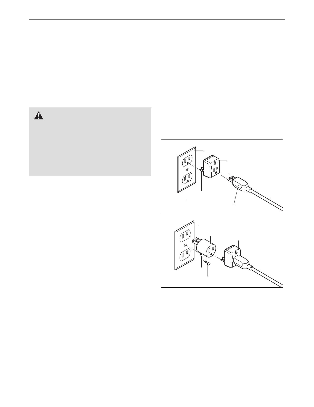
This product is for use on a nominal 120-volt circuit,
and has a grounding plug that looks like the plug illus-
trated in drawing 1 below. A temporary adapter that
looks like the adapter illustrated in drawing 2 may be
used to connect the surge suppressor to a 2-pole
receptacle as shown in drawing 2 if a properly
grounded outlet is not available.
The temporary adapter should be used only until a
properly grounded outlet (drawing 1) can be installed
by a qualified electrician.
The green-colored rigid ear
, lug, or the like extending
from the adapter must be connected to a permanent
ground such as a properly grounded outlet box cover.
Whenever the adapter is used it must be held in place
by a metal screw
.
Some 2-pole receptacle outlet
box covers are not grounded. Contact a qualified
electrician to determine if the outlet box cover is
grounded before using an adapter
.
DANGER: Improper connection
of the equipment-grounding conductor can
result in an increased risk of electric shock.
Check with a qualified electrician or service-
man if you are in doubt as to whether the
product is properly grounded. Do not modify
the plug provided with the product—if it will
not fit the outlet, have a proper outlet
installed by a qualified electrician.
1
2
Grounded Outlet Box
Grounded Outlet Box
Grounding Plug
Surge Suppressor
Surge Suppressor
Grounding Pin
Adapter
Lug
Metal Screw
Grounded Outlet
Grounding Pin
9
BATTERY INSTALLATION
The console
requires two
"AA" batteries
(not included).
Alkaline batter-
ies are recom-
mended.
To install bat-
teries, open
the battery
cover beneath
the console as
shown. Press
two batteries
into the console;
make sure that the negative (–)
ends of the batteries are touching the springs.
Close the battery cover, push up on the tab, and then
push the tab forward as shown in the inset drawing.
Make sure that the tab locks into place.
STEP-BY-STEP CONSOLE OPERATION
Before operating the console, make sure that the
power cord is properly plugged in (see page 8).
Step onto the
foot rails of the
treadmill. Find
the clip
attached to the
key, and slide
the clip onto
the waistband
of your clothes. Next, insert the key fully into the con-
sole. Test the clip by carefully taking a few steps
backward until the key is pulled from the console.
If the key is not pulled from the console, adjust
the position of the clip as needed.
Follow the steps below to operate the console.
Insert the key fully into the console.
Inserting the key will not turn on the displays. The
displays will turn on when the ON/RESET button
is pressed or when the walking belt is started.
Note: If you just installed batteries, the displays
will already be on.
Reset the speed control and start the walking
belt.
Slide the speed control
down to the
RESET
posi
-
tion.
Note: Each time the
walking belt is stopped,
the speed control must
be moved to the RESET
position before the walk-
ing belt can be restarted.
Next, slowly slide the
speed control up until the
walking belt begins to
move at slow speed. Carefully step onto the walk
-
ing belt and begin walking. Change the speed of
the walking belt as desired by sliding the speed
control.
2
1
DIAGRAM OF THE CONSOLE
Speed Control
Batteries
54
Note: If there is a thin sheet of clear plastic
on the face of the console, remove it before
operating the console.
Clip
Key
Tab
54
10
To stop the walking belt, step onto the foot rails
and slide the speed control to the RESET position.
Note: During the first few minutes that the treadmill
is used, inspect the alignment of the walking belt
and align it if necessary (see page 13).
Monitor your progress with the displays.
TIME/DISTANCE dis-
play—This display
shows the elapsed time
and distance that you
have walked or run, in
miles. Every few sec-
onds, the display will
change from one number to the other, as shown
by the arrows in the display.
CALS/FAT CALS/
SPEED display—This
display shows the
approximate numbers
of calories and fat calo-
ries you have burned.
(See FAT BURNING on
page 14.) In addition, the display shows the
speed of the walking belt, in miles per hour. Every
few seconds, the display will change from one
number to the next, as shown the the arrows in
the display.
To reset the displays at any time, press the
ON/RESET button.
When you are finished exercising, stop the
walking belt and remove the key.
Step onto the foot rails, slide the speed control to
the RESET
position, and remove the key from the
console. The displays will turn off a few minutes
after the key is removed. Note: Any time that the
walking belt is stopped and the ON/RESET
button is not pressed for a few minutes, the
displays will automatically turn off.
HOW TO CHANGE THE INCLINE OF THE TREADMILL
T
o vary the intensity of your exercise, the incline of the
treadmill can be changed. There are four incline lev-
els. Before changing the incline, remove the key
and unplug the power cord. Next, fold the treadmill
to the storage position (see HOW TO FOLD THE
TREADMILL FOR STORAGE on page 10).
To change the incline, first remove the incline pin from
one of the incline legs as shown below. Adjust the
incline leg to the desired height and fully reinsert the
incline pin. Make sure that the incline pin is in the
“locked” position shown in the inset drawing.
Adjust
the other incline leg in the same way.
Make sure that
both incline pins are inserted from the direction
shown.
CAUTION: Before using the treadmill, make sure
that both incline legs are at the same height. Do
not use the treadmill with the incline pins
removed. After you have adjusted the incline legs,
lower the treadmill (see HOW TO LOWER THE
TREADMILL FOR USE on page 11).
HOW TO SELECT KILOMETRES AND MILES
The console can dis-
play distance and
speed in either kilome-
tres or miles. To
change the unit of
measurement, first
UNPLUG THE
POWER CORD
.
Next,
remove the screws
attaching the console
to the console base.
Lift the console a few
inches, being careful
not to pull on the
wires, and turn the
console over. Locate
the small switch on
the back of the console. Move the switch upward or
downward to select kilometres or miles. Reattach the
console to the console base. After changing the unit
of measurement, remove one of the batteries from
the console for about five seconds and then rein
-
sert it. This will reset the console.
4
3
Incline
Pin
Incline
Pin
Incline
Pin
Arrow
Arrow
Console
Screws
Screws
Switch
11
HOW TO FOLD AND MOVE THE TREADMILL
HOW TO FOLD THE TREADMILL FOR STORAGE
Before folding the treadmill, unplug the power cord. CAUTION:
You must be able to safely lift 20 kg (45 lbs.) in order to
raise, lower or move the treadmill.
1. Hold the treadmill with your hands in the locations shown
at the right. To decrease the possibility of injury, bend
your legs and keep your back straight. As you raise
the treadmill, make sure to lift with your legs rather
than your back.
Raise the treadmill about halfway to the
vertical position.
2. Move your right hand to the position shown and hold the
treadmill firmly. Raise the treadmill until the storage latch
closes over the catch.
Make sure that the storage latch
is fully engaged over the catch.
To protect the floor or carpet from damage, place a
mat under the treadmill. Keep the treadmill out of
direct sunlight. Do not leave the treadmill in the stor-
age position in temperatures above 30º C (85° F).
Closed
Catch
Storage
Latch
HOW TO MOVE THE TREADMILL
Before moving the treadmill, convert the treadmill to the
storage position as described above. Make sure that the
storage latch is fully engaged over the catch.
1. Hold the upper ends of the handrails. Place one foot on
one of the front wheels as shown.
2. Tilt the treadmill back until it rolls freely on the front
wheels.
Carefully move the treadmill to the desired loca-
tion.
T
o reduce the risk of injury
, use
extreme caution
while moving the treadmill. Do not attempt to move
the treadmill over an uneven surface.
3. Place one foot on a front wheel, and carefully lower the
treadmill until it is resting in the storage position.
HOW TO LOWER THE TREADMILL FOR USE
1. Refer to drawing 2 above. Hold the upper end of the treadmill with your right hand as shown. Using your left
thumb, press the storage latch and hold it. Pivot the treadmill until the frame and foot rail are past the storage
latch.
2. Refer to drawing 1. Hold the treadmill firmly with both hands, and lower the treadmill to the floor
.
Do not
drop the treadmill frame to the floor
. CAUTION: T
o decrease the possibility of injury
, bend your legs
and keep your back straight.
Base
Front
Wheels
12
MAINTENANCE AND TROUBLESHOOTING
Most treadmill problems can be solved by following the steps below. Find the symptom that applies, and
follow the steps listed. If further assistance is needed, call our Customer Service Department toll-free at
1-888-936-4266, Monday through Friday 8h00 until 18h30 Eastern T
ime (excluding holidays).
PROBLEM: The power does not turn on
SOLUTION:
a. Make sure that the power cord is plugged into a surge suppressor, and that the surge suppres-
sor is plugged into a properly grounded outlet (see page 8). Use only a single-outlet surge sup-
pressor that meets all of the specifications described on page 8. Important: The treadmill is not
compatible with GFCI-equipped outlets.
b. After the power cord has been plugged in, make sure that the key is fully inserted into the console.
c. Check the circuit breaker located on the treadmill
frame near the power cord. If the switch pro-
trudes as shown, the circuit breaker has tripped.
To reset the circuit breaker, wait for five minutes
and then press the switch back in.
PROBLEM: The power turns off during use
SOLUTION: a. Check the circuit breaker located on the treadmill frame near the power cord (see 1. c. above). If
the circuit breaker has tripped, wait for five minutes and then press the switch back in.
b. Make sure that the power cord is plugged in. If the power cord is plugged in, unplug it, wait for
five minutes, and then plug it back in.
c. Remove the key from the console. Reinsert the key fully into the console.
d. If the treadmill still will not run, please call our Customer Service Department, toll-free.
PROBLEM: The displays of the console do not function properly
SOLUTION: a. Check the batteries in the console (see page 9). Most problems are the result of drained batter-
ies.
b.
Remove the key from the console and
UNPLUG
THE POWER CORD.
Remove the screws from the
hood. Carefully remove the hood. Locate the Reed
Switch (76) and the Magnet (47) on the left side of
the Pulley (77). Turn the Pulley until the Magnet is
aligned with the Reed Switch. Make sure that the
gap between the Magnet and the Reed Switch is
about 3mm (1/8”). If necessary, loosen the 3/4” Tek
Screw (3) and move the Reed Switch slightly.
Retighten the Screw. Re-attach the hood, and run
the treadmill for a few minutes to check for a correct
speed reading.
Tripped
Reset
c
47
76
3
b
T
op V
iew
3mm
77
13
PROBLEM: The walking belt slows when walked on
SOLUTION:
a.
Use only a single-outlet surge suppressor that meets all of the specifications described on page 8.
b. If the walking belt is overtightened, treadmill perfor-
mance may decrease and the walking belt may
become damaged. Remove the key and
UNPLUG
THE POWER CORD. Using the allen wrench, turn
both rear roller adjustment bolts counterclockwise,
1/4 of a turn. When the walking belt is properly tight-
ened, you should be able to lift each side of the
walking belt 7-10 cm (2-3 inches) off the walking
platform. Be careful to keep the walking belt cen-
tered. Plug in the power cord, insert the key and run
the treadmill for a few minutes. Repeat until the
walking belt is properly tightened.
c. If the walking belt still slows when walked on, please call our toll-free Customer Service
Department.
PROBLEM: The walking belt is off-center or slips when walked on
SOLUTION: a. If the walking belt is off-center, first remove the key
and UNPLUG THE POWER CORD. If the walking
belt has shifted to the left, use the allen wrench to
turn the left rear roller bolt clockwise 1/2 of a turn; if
the walking belt has shifted to the right, turn the
bolt counterclockwise 1/2 of a turn. Be careful not to
overtighten the walking belt. Plug in the power cord,
insert the key and run the treadmill for a few minutes.
Repeat until the walking belt is centered.
b. If the walking belt slips when walked on, first remove
the key and UNPLUG THE POWER CORD. Using
the allen wrench, turn both rear roller bolts clockwise,
1/4 of a turn. When the walking belt is correctly tight-
ened, you should be able to lift each side of the walk-
ing belt 2 to 3 inches off the walking platform. Be
careful to keep the walking belt centered. Plug in the
power cord, insert the key and carefully walk on the
treadmill for a few minutes. Repeat until the walking
belt is properly tightened.
b
a
Rear Roller
Adjustment Bolts
7-10 cm
b
14
CONDITIONING GUIDELINES
The following guidelines will help you to plan your
exercise program. For more detailed exercise informa-
tion, obtain a reputable book or consult your physician.
EXERCISE INTENSITY
Whether your goal is to burn fat or to strengthen your
cardiovascular system, the key to achieving the desired
results is to exercise with the proper intensity. The
proper intensity level can be found by using your heart
rate as a guide. The chart below shows recommended
heart rates for fat burning and aerobic exercise.
To find the proper heart rate for you, first find your age
at the bottom of the chart (ages are rounded off to the
nearest ten years). Next, find the three numbers at the
top of your age. The three numbers are your “training
zone.”
The lower two numbers are recommended
heart rates for fat burning; the highest number is the
recommended heart rate for aerobic exercise.
Fat Burning
To burn fat effectively, you must exercise at a relatively
low intensity level for a sustained period of time. During
the first few minutes of exercise, your body uses easily
accessible carbohydrate calories for energy
. Only after
the first few minutes does your body begin to use
stored fat calories for energy. If your goal is to burn fat,
adjust the speed and incline of the treadmill until your
heart rate is near one of the lower two numbers in your
training zone.
Aerobic Exercise
If your goal is to strengthen your cardiovascular sys-
tem, your exercise must be “aerobic.”
Aerobic exercise
is activity that requires large amounts of oxygen for
prolonged periods of time. This increases the demand
on the heart to pump blood to the muscles, and on the
lungs to oxygenate the blood. For aerobic exercise,
adjust the speed and incline of the treadmill until your
heart rate is near the highest number in your training
zone.
HOW TO MEASURE YOUR HEART RATE
To measure your
heart rate, stop
exercising and
place two fingers
on your wrist as
shown. Take a six-
second heartbeat
count, and multiply
the result by ten to
find your heart
rate. (A six-second count is used because your heart
rate drops quickly when you stop exercising.) If your
heart rate is too high or too low, adjust the speed or
incline of the treadmill accordingly.
WORKOUT GUIDELINES
A well-rounded workout includes the following three
important parts:
A Warm-up
Start each workout with 5 to 10 minutes of stretching
and light exercise .
A
proper warm-up increases your
body temperature, heart rate, and circulation in prepa
-
ration for exercise.
Training Zone Exercise
After warming up, increase the intensity of your exer-
cise until your pulse is in your training zone for 20 to
60 minutes. (During the first few weeks of your exer-
cise program, do not keep your pulse in your training
zone for longer than 20 minutes.) Breathe regularly
and deeply as you exercise—never hold your breath.
A
Cool-down
Finish each workout with 5 to 10 minutes of stretching
to cool down. This will increase the flexibility of your
muscles and will help to prevent post-exercise problems.
WARNING: Before beginning
this or any exercise program, consult your
physician. This is especially important for
individuals over the age of 35 or individuals
with pre-existing health problems.
15
ORDERING REPLACEMENT PARTS
To order replacement parts, call toll-free 1-888-936-4266, Monday through Friday 8h00 until 18h30 Eastern Time
(excluding holidays). When ordering parts, please be prepared to give the following information:
The MODEL NUMBER OF THE PRODUCt (WCTL25320)
The NAME OF THE PRODUCT (WESLO
®
CADENCE C32 treadmill)
The SERIAL NUMBER OF THE PRODUCT (see the front cover of this manual)
The KEY NUMBER and DESCRIPTION of the desired part(s) (see the PART LIST and EXPLODED DRAW-
ING in the center of this manual)
EXERCISE FREQUENCY
T
o maintain or improve your condition, complete three
workouts each week, with at least one day of rest
between workouts.
After a few months, you may com-
plete up to five workouts each week if desired.
The key to success is to make exercise a regular and
enjoyable part of your everyday life.
ICON OF CANADA, Inc.
900 de l’Industrie
St-Jérôme, Québec
Canada, J7Y 4B8
PLACE
STAMP
HERE
Part No. 211317 R0804A Printed in Canada © 2004 ICON IP, Inc.
®
IMPORTANT: MAIL WITHIN 14 DAYS OF PURCHASE
NAME:
ADDRESS:
COUNTY:
MODEL NO.
RETAILER NAME:
PHONE:
POSTCODE:
SERIAL NO. PURCHASE DATE:
RETAILER ADDRESS:
1) Primary user(s) of product:
o Male o Female o Family
2) Age of primary user:
o 0–24 o 35–44 o 55–64
o 25–34 o 45–54 o 65 and over
3) Annual household income:
o 0–9,999 o 15,000–19,999
o 10,000–14,999 o 20,000+
4) How many times a week do you exercise?
o Less than 3 times o 3 times or more
5) Have you ever purchased an ICON product before?
o Yes o No
6) Where did you first see or hear about ICON products?
o Magazine o Friend/relative
o Newspaper
Ad
o Store
o Other
7)
What was the primary reason for purchasing this ICON product?
o Store Employee o T
elevision
Ads
o Colour
o Electronic Features o Magazine
Ads
o Price
o Product Design o Product Innovation
o Other Features
8) Did you consider purchasing fitness equipment from another
manufacturer?
o No o Yes
What other Manufacturer?
9) Based on your impression of what you have purchased,
would you buy another ICON product?
o Y
es
o No o No Opinion
If not, what other brand name equipment would you purchase?
10) What other type of exercise equipment do you own?
o Bicycle o Exercise Cycle o Treadmill
o Home Gym o W
eight Bench
o Stepper
o Cardio Glide o Other
11) Which type of magazines do you read regularly?
o Sports o Fitness o Motoring
o Business o Computer o General
12) Do you wish to be sent further bulletins about ICON products?
o Yes o No
THANK YOU FOR YOUR TIME
of/du Canada Inc.
PRODUCT WARRANTY REGISTRATION
©
2004 ICON IP
, Inc.
LIMITED WARRANTY
ICON OF/DU CANADA, INC., (ICON), warrants this product to be free from defects in workmanship and material,
under normal use and service conditions, for a period of one (1) year from the date of purchase. This warranty
extends only to the original purchaser
. ICON's obligation under this warranty is limited to replacing or repairing, at
ICON's option, the product through one of its authorized service centers. All repairs for which warranty claims are
made must be pre-authorized by ICON.
This warranty does not extend to any product or damage to a product
caused by or attributable to freight damage, abuse, misuse, improper or abnormal usage or repairs not provided
by an ICON authorized service center, to products used for commercial or rental purposes, or to products used as
store display models. No other warranty beyond that specifically set forth above is authorized by ICON.
ICON is not responsible or liable for indirect, special or consequential damages arising out of or in connection with
the use or performance of the product or damages with respect to any economic loss, loss of property, loss of rev-
enues or profits, loss of enjoyment or use, costs of removal, installation or other consequential damages of what-
soever nature. Some provinces do not allow the exclusion or limitation of incidental or consequential damages.
Accordingly, the above limitation may not apply to you. The warranty extended hereunder is in lieu of any and all
other warranties and any implied warranties of merchantability or fitness for a particular purpose is limited in its
scope and duration to the terms set forth herein. Some provinces do not allow limitations on how long an implied
warranty lasts. Accordingly, the above limitation may not apply to you.
This warranty gives you specific legal rights. You may also have other rights which vary from province to province
or so specified by the retailer of your equipment.
ICON OF/DU CANADA, INC., 900 de l’Industrie, St. Jerôme, QC J7Y 4B8
WESLO is a registered trademark of ICON IP, Inc.
Star Washer (29)–2
3/4” Tek Screw
(3)–4
Wheel Bolt (67)–2
Frame Bolt (70)–2
3/8” Nut (61)–6
Handrail Bolt (42)–4
3/4” Screw (2)–12
Upright Bolt (65)–4
1/4” Washer
(38)–4
3/8” Washer
(66)–8
Spacer Screw
(89)–2
Remove this chart and use it to identify small parts during assembly. Save
this chart and the EXPLODED DRAWING/PART LIST for future reference.
PART IDENTIFICATION CHART
PART LIST—Model No. WCTL25320 R0804A
1 1 Motor Hood
2 12 3/4” Screw
3 21 3/4” Tek Screw
4
5 8” Cable Tie
5 1 Cable Tie
6 1 Clamp Screw
7 2 Cable Tie Clamp
8 1 Left Foot Rail
9 2 Front Isolator
10 2 Front Platform Screw
11 1 Wire Cover
12 2 Incline Leg Washer
13
1 Catch
14 2 Belt Guide
15 4 Belt Guide Screw
16 1 Reed Switch Clip
17 2 Insert Nut
18 2 Hood Anchor
19 1 Motor
20 1 Pulley/Flywheel/Fan
21* 1 Motor/Pulley/Flywheel/Fan
22 1 Motor Tension Bolt
23 1 Motor Tension Washer
24 1 Motor Star Washer
25 1 Motor Tension Nut
26 1 Motor Pivot Bolt
27 2 Frame Spacer
28 1 Power Cord Grommet
29 2 Upright Star Washer
30 1 Power Cord
31 1 Controller
32 8 Electronic Screw
33
1
Choke
34 2 Hood Bracket
35 1 Electronics Bracket
36
1
Circuit Breaker
37
2
Base Leg Endcap
38 7 Roller Adjustment Washer
39
1
Front Roller Adjustment Bolt
40
4
Plastic Fastener
41 1 Motor Belt
42 4 Handrail Bolt
43
4
Isolator Screw
44 2 Cage Nut
45 1 Left Handrail
46 1 Upright Base
47 1 Magnet
48 1 Storage Latch
49 1 Left Endcap
50 1 Ground Wire
51 1 Key/Clip
52
1 Console Base
53 1 Left Upright
54 1 Battery Cover
55* 1 Console Assembly
56 1 Speed Potentiometer
57 4 Hood Screw
58 2 Grommet
59 1 Right Handrail
60 1 Wire Harness
61
7 3/8” Nut
62 1 Right Upright
63 4 Base Pad
64 1 Allen Wrench
65 4 Upright Bolt
66 8 3/8” Washer
67 2 Wheel Bolt
68 2 Wheel
69 1 Speed Control Knob
70 2 Frame Bolt
71 1 Motor Pivot Nut
72 1 Walking Belt
73 1 Belly Pan
74 1 Walking Board
75 1 Large Warning Decal
76 1 Reed Switch/Sensor Wire
77 1 Drive Roller/Pulley
78 2 Isolator
79 1 Frame
80 2 Incline Pin
81
2
Incline Leg
82 2 Incline Leg Cap
83 1 Right Endcap
84
1
Right Foot Rail
85
1
Rear Roller
86 2 Rear Roller Adjustment Bolt
87
1
Warning Decal
88
2
Rear Platform Screw
89 2 Spacer Screw
90 1 Catch Screw
#
1
4” White Wire, M/F
# 1 User’s Manual
* Includes all parts shown in the box
Note: “#” indicates a non-illustrated part.
Key No. Qty. Description Key No. Qty. Description
Specifications are subject to change without notice. See the back cover of the user’s manual for information
about ordering replacement parts.
38
42
2
44
61
5
3
7
4
3
3
3
3
22
23
24
25
32
31
26
35
20
19
61
76
27
3
47
16
89
10
34
3
18
33
51
30
28
36
29
3
18
39
38
27
89
84
10
3
3
79
14
73
3
77
74
72
88
15
80
82
81
38
83
86
82
81
85
49
38
86
64
88
90
13
80
14
15
8
1
21*
75
32
50
3
3
12
12
41
40
40
61
68
67
63
3
66
67
68
61
66
63
3
63
3
63
3
38
42
70
66
42
42
38
38
48
2
2
44
56
69
57
2
2
2
2
52
54
62
53
45
59
46
58
60
61
78
9
43
9
43
78
37
37
60
55*
87
70
66
29
29
34
3
11
66
66
65
65
65
66
65
66
40
40
91
91
58
3
EXPLODED DRAWING—Model No. WCTL25320 R0804A
  • Page 1 1
  • Page 2 2
  • Page 3 3
  • Page 4 4
  • Page 5 5
  • Page 6 6
  • Page 7 7
  • Page 8 8
  • Page 9 9
  • Page 10 10
  • Page 11 11
  • Page 12 12
  • Page 13 13
  • Page 14 14
  • Page 15 15
  • Page 16 16
  • Page 17 17
  • Page 18 18
  • Page 19 19

Weslo Cadence C32 User manual

Category
Treadmills
Type
User manual
This manual is also suitable for

Weslo Cadence C32 treadmill combines advanced technology and innovative design to provide an excellent form of cardiovascular exercise at home. It features a powerful motor that can support users up to 250 lbs, a spacious running belt for a comfortable stride, and adjustable incline levels to add intensity to your workouts. The console offers various workout programs and displays essential fitness stats like time, speed, distance, calories burned, and pulse, helping you track your progress and stay motivated.

Ask a question and I''ll find the answer in the document

Finding information in a document is now easier with AI