Kenmore 000 BTU Multi-Room Air Conditioner Owner's manual

Category
Split-system air conditioners
Type
Owner's manual
Owner's Manual
Manual del Propietario
®
ROOM AIR CONDITIONER
ACONDICIONADOR DE AIRE DE VENTANA
Model, Modelo 580. 74156
Sears, Roebuck and Co., Hoffman Estates, IL 60179 U.S.A.
www.sears.com
TABLE OF CONTENTS ........................2
WARRANTY ..............................................2
SAFETY .....................................................3
ImportantSafety Instructions...................... 3
ELECTRICAL REQUIREMENTS .......4
INSTALLING THE POWER CORD----4
INSTALLATION ........................................5
Installation Requirements ......................... 5
Installation ................................................ 6
How to Install ............................................ 6
Removalfrom Window ................................. 8
OPERATION .............................................9
How and Why ........................................... 9
Normal Sounds ........................................ 9
Capacity and Running Time ..................... 9
Features ................................................. 10
Using the Air Conditioner ....................... 10
Display ................................................... 11
Remote Control ...................................... 12
MAINTENANCE .....................................13
Air Filter Cleaning ................................... 13
Air Conditioner Cleaning ........................ 13
How to Removethe Front Grille.................. 13
How to Replacethe Front Grille .................. 13
TROUBLESHOOTING .........................14
Before Calling for Service ...................... 14
ESPANOL ................................................15
MASTER PROTECTION
AGREEMENTS ......................................31
SERVICE NUMBERS ............ Back Cover
FULL ONE YEAR WARRANTY ON
ROOM AIR CONDITIONER
For one year from the date of purchase, when this
air conditioner is operated and maintained for
normal room cooling according to the instructions in
this owner's manual, Sears will repair this air
conditioner, free of charge, if defective in material or
workmanship.
FULL FIVE-YEAR WARRANTY ON
SEALED REFRIGERATION SYSTEM
For five years from the date of purchase, when this
air conditioner is operated and maintained for
normal room cooling according to the instructions in
this owner's manual, Sears will repair the sealed
refrigeration system (consisting of refrigerant,
connecting tubing, and compressor), free of charge,
if defective in material or workmanship.
WARRANTY SERVICE IS AVAILABLE BY
CONTACTING SEARS SERVICE AT
1-800-4-MY-HOME ®.
Warranty coverage applies only to air conditioners
used for non-commercial, private household
purposes.
This warranty applies only while this product is in
use in the United States.
This warranty gives you specific legal rights, and
you may also have other right which vary from state
to state.
Sears, Roebuck and Co., D/817WA,
Hoffman Estates, IL 60179 U.S.A.
-2-
IMPORTANT SAFETY INSTRUCTIONS
The safety instructions below will tell you how to use your room air conditioner to avoid harm to yourself or
damage to your ROOM AIR CONDITIONER.
FOR YOUR SAFETY
Do not store or use gasoline or other flammable
vapors and liquids in the vicinity of this or any other
appliance. Read product labels for flammability and
other warnings.
_!_'_Vl:l;t_ll_[_!PREVENT ACCIDENTS
To reduce the risk of fire, electrical shock, or injury
to persons when using your air conditioner, follow
basic precautions, including the following:
Be sure the electrical service is adequate for the
model you have chosen.
If the air conditioner is to be installed in a window,
you will probably want to clean both sides of the
glass first. If the window is a triple-track type with a
screen panel included, you may want to remove
the screen completely before installation.
Be sure the air conditioner has been securely and
correctly installed according to the separate
installation instructions provided with this manual.
Save this manual and installation instructions for
possible future use in removing or reinstalling this
unit.
Use gloves when handling the air conditioner.
Be careful to avoid cuts from sharp metal fins on
front and rear coils.
V.'_V_Vl:1:i_]l_[tlELECTRICAL INFORMATION
The complete electrical rating of your new room air
conditioner is stated on the serial plate. Refer to the
rating when checking the electrical requirements.
Be sure the air conditioner is properly grounded.
To minimize shock and fire hazards, proper
grounding is important. The power cord is
equipped with a three-prong grounding plug for
protection against shock hazards.
Your air conditioner must be plugged into in a
properly grounded wall receptacle. If the wall
receptacle you intend to use is not adequately
grounded or protected by a time delay fuse or
circuit breaker, have a qualified electrician install
the proper receptacle.
Do not run air conditioner with a protective
covering. This could result in mechanical damage
within the air conditioner.
Do not use an extension cord or an adapter
plug.
_ Avoid fire hazard or electric shock.
Do not use an extension cord or an adapter plug.
Do not remove any prong from the power cord.
Grounding type
wall receptacle
Do not under any
circumstances cut,
remove, or bypass
the grounding prong
from this plug.
Power supply cord _,
with 3-prong
%
grounding plug
ENERGY SAVING IDEAS
The capacity of the room air conditioner must fit
the room size for efficient and satisfactory
operation.
install the room air conditioner on the shady side
of your home. A window that faces north is best
because it is shaded most of the day.
Do not block air conditioner flow inside with blinds,
curtains, or furniture, or outside with shrubs,
enclosures, or other buildings.
Close the floor and wall registers and the fireplace
damper so cool air does not escape up the
chimney or into the duct work.
Keep blinds and drapes in other windows closed
during the sunniest part of the day.
Clean the air filter as recommended in the
MAINTENANCE section of this manual.
Proper insulation and weather stripping in your
home will help keep warm air out and cool air in.
External house shading with trees, plants or
awnings will help reduce the air conditioner's work
load.
Operate heat producing appliances such as
ranges, washers, dryers, and dishwashers during
the coolest part of the day.
-3-
OBSERVEALL LOCAL CODES AND
ORDINANCES.
DO NOT, UNDER ANY CIRCUMSTANCES,
REMOVE THE POWER SUPPLY CORD
GROUND PRONG.
ELECTRICAL GROUND IS REQUIRED ON
THIS APPLIANCE.
For 230/208 volt 60 Hz, AC only, 15A fused
and properly grounded electrical supply is
required. A time delay fuse or time delay circuit
breaker is recommended. Use a dedicated
circuit, serving only this appliance.
DO NOT USE AN EXTENSION CORD.
RECOMMENDED GROUNDING METHOD
For your personal safety, this appliance must
be grounded. This appliance has a power
supply cord with a 3-prong grounding plug. To
minimize possible shock hazard, the cord must
be plugged into a mating grounding type wall
receptacle and grounded in accordance with
the National Electrical Code (ANSt/NFPA 70)
latest edition and all local codes and
ordinances. If a mating wall receptacle is not
available, it is the personal responsibility and
obligation of the customer to have a properly
grounded 3-prong wall receptacle installed by a
qualified electrician.
Electrical Shock Hazard
Plug into a grounded 3 prong outlet.
Do not remove ground prong.
Do not use an adapter.
Do not use an extension cord.
Failure to follow these instructions can result
in death, fire, or electrical shock.
[_3-prong
11f'-_ I grounding
,J-prong _ Ill _°"_ J type wall
g[ounalng _....--_ I_L_.._ j receptacle
N Ground
Power N prong
supply
cord
You can choose between two methods below according to your window stool shape and preference.
USING SLIT "A"
Fasten the stopper using 2 screw holes, and lead
out the power cord through slit "A".
Power
USING SLIT "B"
Fasten the stopper using left screw hole, and rotate
properly to lead the power cord out through slit "B".
-4-
INSTALLATION REQUIREMENTS
Your air conditioner will install into standard double
hung windows with actual clear opening widths of
29 to 41 inches (737mm to 1041mm) (FIG. 1)
Lower sash must open sufficiently to allow a clear
vertical opening of 18 inches (457mm). Side louvers
and the rear of the air conditioner must have clear
air space to allow enough airflow through the
condenser for heat removal. The rear of the unit
must be outdoors, not inside a building or garage.
I I J........Sash
18"min, _I , ,
inner sill L[_ vvmaow
,_"H_" :,___--Offset
(i _ ,, ,,j/ ;,;_ Sill
_, _: _i" Exterior
FIG 1
Interior wall "- .... "
ELECTRICAL SERVICE
Check your available electrical service. The power
supply available must be the same as that shown on
the unit nameplate (found on right side of cabinet).
All models are equipped with a 3-prong service plug
to provide proper service and safe positive
grounding. Do not change plug in any way. Do not
use an adapter plug. If your present wall outlet does
not match your plug, call a qualified electrician to
make the necessary corrections.
SAVE CARTON and this OWNER'S MANUAL for
future reference. The carton is the best way to store
unit during winter or when not in use.
To avoid risk of personal injury, property damage,
or product damage due to the weight of this
device and sharp edges that may be exposed:
Air conditioners covered inthis manual pose an
excessiveweight hazard. Two or more people
are needed to move and install the unit.
To prevent injury or strain, use proper lifting and
carrying techniques when moving unit.
Carefully inspect locationwhere air conditioner
will be installed. Be sure itwill support the
weight of the unit over an extended period of
time.
Handle airconditionerwith care.Wear
protective gloves whenever lifting or carrying the
unit. AVOID thesharp metal fins of front and
rear coils.
Makesure air conditionerdoes not fall during
installation.
INSTALLATION HARDWARE
B C D E
F G H I J K
FIG.2
ITEM NAME OF PARTS Q'TY
A SIDE CURTAIN 2
B SUPPORT BRACKET 2
C SILL BRACKET 2
D LOCK NUT 4
E SCREW: 25/64" 11
F SCREW: 13/16" 7
G SCREW: 9/16" 5
H M-SCREW 2
I CARRIAGE BOLT 2
J FOAM SEAL 1
K FOAM STRIP 1
L WINDOW LOCKING BRACKET 1
M DRAIN PIPE 1
REQUIRED TOOLS:
Tight Fitting gloves
Standard screwdriver
Phillips screwdriver
Pliers
Sharp knife
3/8-inch open end wrench or adjustable wrench
1/4-inch hex socket and ratchet
Tape measure
Electric drill
ll4-inch drill bit
-5-
INSTALLATION
Pick a location which will allow you to blow the cold
air into the area you want. Windows used for
installation must be strong enough to support the
weight of the air conditioner. Good installation with
special attention to the proper position of the unit
will lessen the chance that service will be needed•
When cooling more than one room, installation
location is very important. To cool your rooms, cold
air must be blown from the air conditioner in a
straight path.
HOW TO INSTALL
If the air conditioner is blocked by a storm
window frame, see step 16 on page 8 before
beginning to install.
D Remove the screws which fasten the cabinet at
the back and side of the unit. Save side screws.
Discard back screws•
_ Slide the unit out of the cabinet by gripping the
base pan handle and pull forward while bracing the
cabinet.
FIG. 4
_J Cut the FOAM SEAL (ITEM J) to fit the
underside of the window sash. Peel off the backing
and attach the FOAM SEAL as shown in Fig. 5.
D Insert the side curtain (ITEM A) into the upper guide
and lower guide of the air conditioner. Fasten the curtains
to the unit with screws (ITEM E).
ITEME
Lower Guide
ITEME FIG.6
_1_ Open the window. Mark a line on the center of the
window inner sill. Loosely attach the sill bracket (ITEM C)
to the support bracket (ITEM B) using the carriage bolt
(ITEM I) and the iock nut (ITEM D).
ITEM I
r_ Attach the sill bracket to the window sill using the
screws (ITEM F). Carefully place the cabinet on the
window inner sill and align the center of the cabinet
front with the center line marked on the window inner
sill.
_Machinescrew
Cabinet_ / andlocknut
trackhole rOuter
/ edgeof
ITEM windowsill
/
Carriage bolt ...............
and lock nut Sill I_racket FIG. 8
H Using the M-screw (ITEM H) and the lock nut
(ITEM D), attach the support bracket to the cabinet
track hole. Use the first track hole after the sill bracket
on the outer edge of the window sill. Tighten the
carriage bolt and the lock nut. Be sure the cabinet
slants downward 1/4" from level.
CAUTION: Do not drill a hole in the bottom pan. The
unit is designed to operate with approximately 1/2" of
water in bottom pan.
FIG. 5
Lowerguide
INDOOR
Cabinet
OUTDOOR
FIG. 9
-6-
[_ Pull the bottom window sash down behind the
upper guide until they meet.
NOTE:
Do not pull the window sash down so tightly that the
movement of sliders is restricted. Attach the cabinet
to the window inner sill by driving the screws (ITEM F)
through the cabinet into window inner sill.
The cabinet should be installed with a very slight tilt
downward by 1/4" from level.
Window sash Ipper guide
Cabinet j
Frame curtain
ITEM F
FIG. 10
D Expand side curtains to fill opening.
Attach each side curtain to the window sash using 4
screws (ITEM G). (FIG. 11)
_I_ Attach the window locking bracket (ITEM L) with
a screw(ITEM G). See FIG. 12.
FIG. 12
_11 DRAINAGE
A drain hole is provided at the rear of the air
conditioner unit. Select a drain method according to
the following.
Remove the hole rubber from the base-pan.
Connect a drain elbow of 9/16" inside diameter to
the drain pipe.
Connect a drain hose of 9/16" inside diameter to the
drain elbow. (Drain hose is not supplied.)
elbow
Drain
hose
FIG. 13
[]Slide the air conditioner into the cabinet. (FIG. 14)
CAUTION: For security purposes, reinstall side
screws that were removed in step 1.
Scre_ower Cord _ Screw
FIG. 14
[]Cut the foam stripl (ITEM K) to the proper length
and insert between the upper window sash and the
lower window sash. (FIG. 15)
FIG. 15
_1 Adjust the vent handle before the decorative
front is attached. (FIG. 16)
Straighten the lever, as shown. Pull down part _)to
align with part (_.
FIG. 16
-7-
_I_ FRONT INSTALLATION
Install the front grille(packed separately) onto the
cabinet as follows:
Hook upper tabs of front grille into slots on the
cabinet top. (FIG. 17)
Push front grille's tips towards the cabinet in order
to snap side tabs into the cabinet. (FIG. 17)
Open the inlet grille. (FIG. 18)
Install the screw (ITEM E) through the front grille.
(FIG. 18)
Close inlet grille. (FIG. 19)
Front Installation
FIG. 17
ITEM E
Front Installation
FIG. 18
Front Installation FIG. 19
_rr_ IF AIR CONDITIONER IS BLOCKED BY
STORM WINDOW FRAME
If storm window presents interference, fasten a 2"
wide wood strip to the inner window sill across the full
width of the sill. The wood strip should be thick
enough to raise the height of the window sill so that
the unit can be installed without interference from the
the storm window frame. See FIG. 20.
Top of wood strip should be approximately 3/4"
higher than the storm window frame to help
condensation to drain properly to the outside.
Install a second wood strip (approximately 6" long by
11/2" wide and same thickness as first strip) in the
center of the outer sill flush against the back of the
inner sill. Screw the L brackets into this strip.
This will raise the L bracket as shown in FIG. 20.
1 1/2"min.
WOODSTRIPMOUNTED (38ram)
ONTOPOFINNERSILL _='_1 I_'I_ 314" 1
"--._- I CLEARANCET
STORM #
/ I / #v _ WINDOW
iNNER ILBRACKET/ L FRAME
SILL FoW#O_ATcR_pT [_
J J OUTER
L_q l s'LL
INSIDEI I OUTSIDE
FIG. 20
REMOVAL FROM WINDOW
Turn off and unplug the air conditioner.
Remove the front grille. See HOW TO REMOVE THE
FRONT GRILLE. Refer to page 13.
Unscrew the side screws that you installed in Step 15.
Slide the air conditioner out of the cabinet.
BE CAREFUL NOT TO DROP IT. Hold onto it firmly the
whole way sliding it out. Once removed, set it safety out
of the way.
Remove the L bracket from window frame and the sash
seal from between the windows.
Unscrew the side curtains from the window frame. Fold
them back to the sides of the cabinet.
Remove screws attaching cabinet to inner sill. Be careful
not to let cabinet fall once screws are removed.
Remove cabinet from window opening.
Place air conditioner into cabinet. Reinstall side screws
and Front GriJJe.
Place unit and all assembly hardware in air conditioner
shipping carton, and store in clean, dry place.
Air conditioners covered inthis manual pose an
excessive weight hazard. Two or more people
are needed to move and install the unit.
To prevent injury or strain, use proper lifting and
carrying techniques when moving unit.
When handlingthe air conditioner, becareful to
avoid cutsfrom sharp metal fins on front and
rear coils.
Makesure air conditionerdoes not fall during
removal.
-8-
HOW AND WHY
Your room air conditioner provides the following
functions to make hot weather living more
comfortable:
Cools and circulates room air.
Lowers humidity by removing excess moisture.
Filters out summertime dust, dirt, and some
airborne impurities.
The air conditioner performs these functions by
drawing room air through a filter which traps dust
and dirt particles. The air then passes over a
cooling coil which refrigerates the air and removes
excess moisture. The same air is then returned to
the room- cooler, drier, and cleaner. Moisture
removed from the room air is carried to the outside
and evaporated.
Your air conditioner is designed to be easy to
operate and to provide plenty of cooling power.
NORMAL SOUNDS FIG.21
Aside from the regular fan motor and compressor
sounds coming from your air conditioner, you will
once in a while hear a pinging sound. This is the
result of moisture being picked up from the air in the
room and thrown against the air conditioner's fan.
This is normal and should not be cause for concern.
Also, do not be alarmed if you hear a slight hissing
or gurgling sound coming from your air conditioner
after it is off. These are normal coolant noises.
CAPACITY AND RUNNING TIME
Proper unit size is important in deciding the desired
comfort for the area you want to cool. An
undersized unit will not have the capability to cool,
leaving the area uncomfortably warm. The proper
size is determined by the number of square feet in
the area to be cooled, indoor and outdoor
temperature and humidity.
Whenever the heat or humidity load is above normal
the air conditioner must run longer and more often
to keep the desired temperature you have selected,
Under heavy heat load conditions the air conditioner
may need to run constantly to keep the temperature
you want.
At times using the MED FAN setting to circulate the
room air may make it comfortable even though the
air is not being cooled. This will decrease your cost
of use.
Compressor
The modern high efficiency
compressor may have a high
pitched hum or pulsating
noise that cycles on and off.
Unit Vibration
The unit may vibrate
and make noise
because of poor wall
or window construction.
Fan
You may hear air
movement from
the fan.
You may hear droplets of water hitting
the condenser causing a pinging or
clicking sound.
FIG. 21
-9-
FEATURES
1 15 6 5
4 32714
9 8
11 1210 13 16
FIG. 22
1. Cabinet
2. Vertical Air
Direction Louvers
3. Horizontal Air
Direction Louvers
4. Inlet Grille
5. Air Filter
6. Front Grille
7. Control Board
8. Power Cord
9. Evaporator Coil
10. Condenser
11. Compressor
12. Base pan
13. Brace
14. Upper Guide
15. Curtain
16. Remote Control
USING THE AIR CONDITIONER
IF.'_'iVl:_B_ll_[_!To reduce the risk of fire, electric
shock, or injury to persons, read the important
SAFETY instructions section before operating this
appliance
To begin operating the air conditioner after
installation, follow these steps:
1. Plug in the air conditioner. (To prevent electrical
hazards, do not use an extension cord or an
adapter plug.)
2. Set the exhaust vent to the CLOSE position.
3. Set the TEMP Control to the coolest setting.
4. Set the MODE control at the highest COOL level.
5. Adjust the louvers for comfortable air flow.
6. Once the room has cooled, adjust the TEMP and
Mode Control to the setting you find most
comfortable.
NOTE : If the air conditioner is turned off, wait 3
minutes before restarting. This allows pressure
inside the compressor to equalize. Failure to wait 3
minutes before restarting may cause inefficient
operation.
If you move the TEMP Control to a warmer, then
immediately back to a cooler setting, the unit will
shut off. Wait 3 minutes before restarting.
VENT CONTROL
The Vent Control allows the air conditioner to
either recirculate inside air (CLOSE) or exhaust
air to the outside (OPEN). (FIG. 23)
The CLOSE position is used when maximum
cooling is desired. It may also be used for air
recirculation without cooling when the air
conditioner is set in the FAN position.
The OPEN position removes stale air from the
room and exhausts it to the outside. Fresh air is
drawn into the room through your home's
normal air passages.
The OPEN or CLOSE position can be used with
any fan selection.
PULL OPEN / PUSH CLOSE
FIG. 23
-10-
DISPLAY
I FAN SPEED
Every time you push this button, it advances the setting as follows: {High -_ Low-_ Med-_ High}
REMOTE CONTROL SlGNAL
RECEIVER
- SHUT-OFF TIME
• You will usually use shut-off time while you sleep.
• If unit isrunning, Timersets numberof hours untitshut-off.
• Everytime you pushTimerbutton, it advancesthe Timersetting
asfollows: 1 Hour-* 2 Hours........ 12 Hoursmaximum.
- START TIME
If unit isoff,Timer sets numberof hours beforeunit starts.
SETTING
• This button can automatically control the
temperature of the room.
The temperature can be set within a range
of 60°F to 86°F by increments of 1°F.
POWER
Toturn the airconditioner ON, pushthe
button.
Toturn the airconditioner OFF, push
the button again.
• This buttontakes priorityover any other
button.
• When you first turn it on, the air conditioneris
on the High cool modeand the Temp.at 72°F.
Every timeyou pushTimer button, it advancesthe Timer setting asfollows: 1 Hour-, 2 Hours......... 12Hours
maximum.
MODE
- Every time you push this button, it will shift among COOL, ENERGY SAVER and FAN.
- ENERGY SAVER:
The fan stops when the compressor stops cooling.
Approximately every 3 minutes the fan will turn on and check the room air to determine if cooling is
needed.
In failure of electric power, the unit runs as previous setting operation.
HORIZONTAL AIR DIRECTION CONTROL VERTICAL AIR DIRECTION CONTROL
The vertical air direction is adjusted by moving the
The horizontal air direction is adjusted by moving horizontal louvers up and down with your fingertips.
the vertical louvers right and left with your (FIG. 25)
fingertips. (FIG. 24)
FIG. 24 FIG. 25
-11-
REMOTE CONTROL
NOTE: The Remote Control will not operate properly if strong light shines on the sensor window of the Air
Conditioner or if there are obstacles between the Remote Control and the Air Conditioner.
Every time you push button, you will hear a beep from the Air Conditioner.
POWER
To turn the air conditioner ON, push the button. To turn the air conditioner OFF, push the
button again. This button takes priority over any other button.
When you first turn it on, the air conditioner is on the High cool mode and the Temp. at
72°F
TEMPERATURE SETTING
This button can automatically control the temperature of the room.
The temperature can be set within a range of 60C'Fto 86C'F by increments of I°F.
FAN SPEED
Every time you push this button it advances the setting as follows:
(High -, Low -, Med -, High)
TIMER
- SHUT-OFF TIME
You will usally use shut-off time while you sleep.
If unit is running, Timer sets number of hours until shut-off.
Every time you push Timer button, it advances the Timer setting as follows: ! Hour -*
2 Hours ......... 12 Hours maximum.
- START TIME
If unit is off, Timer sets number of hours before unit starts.
Every time you push Timer button, it advances the Timer setting as follows: ! Hour-*
2 Hours......... 12Hoursmaximum.
FAN SPEED
TIMER MODE
MODE
- Every time you push this button, it will shift among COOL, ENERGY SAVER and FAN.
- ENERGY SAVER
The fan stops when the compressor stops cooling.
Approximately every 3 minutes the fan will turn on and check the room air to determine if cooling is needed.
HOW TO INSERT BATTERIES INTO REMOTE CONTROL
1. Remove the cover from the back of the remote
controller.
Open the cover according to the arrow direction on the
cover.
2. Insert two batteries.
Be sure that the (+) and (-) directions are correct.
Be sure that both batteries are new.
3. Re-attach the cover.
Do not use rechargeable batteries.
Such batteries differ from standard dry cells in shape,
dimensions, and performance.
Remove the batteries from the remote controller if the air
conditioner is not going to be used for an extended
length of time.
-12-
AIR FILTER CLEANING
The Air Filter will become dirty as it removes dust
from the inside air. It should be washed at least
every 2 weeks. If the Air Filter remains full of dust,
the air flow will decrease and the cooling capacity
will be reduced, possibly damaging the unit.
Pull the inlet grille forward, grasping both tabs,
then pull out the air filter. (FIG. 26)
Wash the Air Filter under the faucet with warm
water. Be sure to shake off all the water before
replacing the filter. (FIG.27)
FIG. 26
FIG. 27
AIR CONDITIONER CLEANING
Clean the front grille and inlet grille by wiping with a
cloth dampened in a mild detergent
solution.(FIG.28)
The cabinet may be washed with mild soap or
detergent and lukewarm water, then polished with
liquid appliance wax.
To ensure continued peak efficiency, the condenser
coils (outdoor side at the unit) should be checked
periodically and cleaned if they become clogged
with soot or dirt from the atmosphere. Brush or
vacuum exterior coils to remove debris from fins.
FIG. 28
HOW TO REMOVE THE FRONT
GRILLE
Open the inlet grille downward.
Remove the screw securing the Front Grille.
Push the grille up from the bottom and pull the top
of the grille away from the case to lift the top tabs
out of their slots.
Inlet Grille
d
1_ront Grille
° _u_ U \ "
FIG. 29
HOW TO REPLACE THE
FRONT GRILLE
Attach the front grille to the cabinet by inserting the
tabs on the grille into the slots on the front of the
cabinet. Push the grille in until it snaps into place.
FIG. 30
-13-
BEFORE CALLING FOR SERVICE
Check the following list to be sure a service call is really necessary. A quick reference to this manual may
help you avoid an unneeded service call.
THE AIR CONDITIONER WILL NOT OPERATE
Check if...
Wail plug disconnected.
House fuse blown or circuit breaker tripped,
Power is OFF.
Unit was turned off and then on too quickly.
TEMP Control set warmer than room temperature.
Then...
Push plug firmly into waltoutlet,
Replace fuse with time delay type or reset circuit breaker.
Push the power button.
Set unit off and wait 3 minutes before restarting.
Set TEMP Control to cooler temperature.
AIR FROM UNIT DOE8 NOT FEEL COLD ENOUGH.
Check if... Then...
FANSPEEDsetatLOW. PushFANSPEEDbuttontosetatHI.
TEMPControlsettoowarm. SetTEMPControltoacoolertemperature.
Roomtemperaturebelow70F (21C). Coolingmaynotoccuruntilroomtemperaturerisesabove70F (21C).
Temperaturesensingtubetouchingevaporatorcoil, Straightentubeawayfromevaporatorcoil.
locatedbehindfrontgrille.
THEAIRCONDITIONERCOOLING,BUTROOM18TOOWARM- ICEFORMINGONCOOLINGCOILBEHINDFRONTGRILLE.
Check if... Then...
Outdoortemperaturebelow7O°F(21_'C). Todefrostthecoil,settheMODEto FAN.
Airfiltermaybedirty. Cleanairfilter.RefertoMaintenancesectionofowner'smanual.
TEMPControlsettoocoldfornight-timecooling. Todefrostthecoil,settheMODEto FANor "HighCool"withthe
TEMPcontroltowarmertemperature.
THEAIRCONDITIONERCOOLING,BUTROOM18TOOWARM.
Check if... Then...
Dirtyairfilter- airrestricted. Cleanairfilter.RefertoMaintenancesectionofowner'smanual.
TEMPControlsettoowarm. SetTEMPControltocoolertemperature.
Frontofunitisblockedbydrapes,blinds,furniture,etc. Clearblockageinfrontofunit.
Airdistributionisrestricted.
Doors,windows,registers,etc.open.Coldairescapes. Closedoors,windows,registers,etc.
Unitrecentlyturnedonin hotroom. Allowadditionaltimetoremovestoredheatfromwalls,ceiling,floor,andfurniture.
THE AIR CONDITIONER TURN8 ON AND OFF RAPIDLY.
Check if... Then...
I Outsidetemperatureis extremelyhot. I SetFANSPEEDon HItobringairpastcoolingcoilsfaster. I
NOISE WHEN UNIT 18 COOLING.
Check if... Then...
Soundoffanhittingwaterfromthemoistureremovalsystem. Thisisnormalwhenhumidityishigh.Closedoors,windows,andregisters.
Windowvibration- poorinstallation. Referto installationinstructionsor checkwith installer.
WATER DRIPPING INSIDE ROOM WHEN UNIT 18 COOLING.
Check if... Then...
Theairconditionerisimproperlyinstalled, installationTiltairconditionerinstructionsslightlyortochecktheoutsidewithinstaller,toallowwaterdrainage.Referto
WATER DRIPPING OUTSIDE WHEN UNIT 18 COOLING.
Check if... Then...
Theunitisremovinglargequantitiesof moisture ThisisnormaIduringexcessivelyhumiddays.
fromhumidroom.
-14-
INDICE DE MATERIAS ............................. 1
GARANTiA ................................................ 1
5
5
6
6
SEGURIDAD .............................................. 1
Importantes instruccionesde seguridad .....1
REQUERIMIENTOS ELI_CTRICOS ......... 17
INSTALACION DEL CABLE EL_:CTRICA---17
INSTALAClON ........................................... 18
Requerimientos para instalaci6n .......... 18
Installaci6n ............................................ 19
C6mo instalarlo ..................................... 19
La eliminaci6n de la ventana ................. 21
OPERAClON .............................................. 22
C6mo y por que ..................................... 22
Sonidos normales .................................. 22
Capacidad y tiempo de funcionamiento ---22
Caracteristicas ..................................... 23
Uso del equipo de aire acondicionado--23
Despliegue ............................................ 24
Control remoto ....................................... 24
MANTENIMIENTO .................................... 26
Limpieza del filtro del aire ...................... 26
Limpiezadelequipode aireacondicionado....26
C6mo sacar la rejilla frontal ................... 26
C6mo a reemplaza el grille anterior ......26
CORRECClON DE FALLAS ...................... 27
Antes de LlamarparaServicio...................... 27
ACUERDOS DE PROTECClON
ESPEClALIZADA ...................................... 31
PARA PEDIR SERVIClO----Cubierta Trasera
GARANTiA DE UN ANO POR EL
EQUlPO DE A!RE ACONDIClONADO
DE HABITAClON
Durante un aSo completo a partir de la fecha de
compra, si este equipo de aire acondicionado recibe
mantenimiento y se utiliza para el enfriamiento
normal de habitaci6n seg_n las instrucciones
indicadas en este manual del propietario, Sears
reparara gratuitamente este equipo de aire
acondicionado, si tiene alg_n defecto en materiales
o fabricaci6n.
GARANTiA TOTAL DE CINCO ANOS
POR EL 81STEMA DE REFRIGERACION
HERMETICAMENTE SELLADO
Durante cinco a_os a partir de la fecha de compra,
si este equipo de aire acondicionado recibe
mantenimiento y se utiliza para el enfriamiento
normal de habitaci6n seg_n las instrucciones
indicadas en este manual del propietario, Sears
reparara gratuitamente el sistema de refrigeraci6n
hermeticamente sellado (que consiste en el agente
refrigerante, los tubos de conexion y el compresor),
si tiene algQn defecto en materialeso fabricaci6n.
EL SERVlCIO DE GARANTiA ES
DISPONIBLE CONTACTANDO AL SERVlClO
SEARS AL 1-800-4-MY-HOME ®
La proteccion de garantia cubre unicamente a
los equipos de aire acondicionado usados para
uso domestico y no para uso comercial.
Esta garantia s61o tiene validez mientras el
producto se este usando en los Estados
Unidos.
Esta garantia le da derechos legales
especificos y usted puede tener otros
derechos que varian de estado en estado.
Sears, Roebuck and Co., D/817WA,
Hoffman Estates, IL 60179 U.S.A.
-15-
IMPORTANTES INSTRUCCIONES DE SEGURIDAD
Las siguientes instrucciones de seguridad le indicar&n c6mo usar su equipo de aire acondicionado de
habitaci6n para evitar dafios para usted mismo y para su EQUIPO DE AIRE ACONDIClONADO.
I/'._'.lJtvl_;ll_I[_r,1POR SU SEGURIDAD
No almacene ni use gasolina u otros vapores y
liquidos inflamables cerca de este o cualquier otro
electrodomestico. Lea las etiquetas de los
productos para ver si contienen advertencias sobre
el caracter inflamable de los mismos y otras
advertencias.
PARA PREVENIR ACCIDENTES
Para reducir el riesgo de incendios, descargas
electricas o lesiones personales al usar su equipo
de aire acondicionado, tome las precauciones
basicas, entre las que estan las siguientes:
AsegQrese de que la alimentacion electrica sea la
apropiada para el modelo que usted ha elegido.
Si el equipo de aire acondicionado debe instalarse
en una ventana, a usted probablemente le
conviene limpiar primero ambos lados del vidrio.
Si la ventana es del tipo de tres paneles con un
panel incluido de pantalla, le conviene sacar la
ventana completamente antes de la instalaci6n.
AsegQrese de que el equipo de aire
acondicionado ha sido instalado correctamente y
con seguridad segOn se sefiala en las
instrucciones separadas de instalacion que vienen
en este manual. Conserve este manual y las
instrucciones de instalaci6n para usarlos
posiblemente en el futuro al sacar o volver a
instalar esta unidad.
Use guantes al manejar el equipo de aire
acondicionado, tenga cuidado para evitar cortadas
con las afiladas aletas met&licas que se hallan en
los serpentines frontales y posteriores.
INFORMACION ELECTRICA
En la placa de serie del fabricante se indica cu_ll es
la capacidad electrica nominal completa de su nuevo
equipo de aire acondicionado para habitaci6n. Consulte
esta placa cuando vaya a verificar los requerimientos
electricos.
Aseg0rese de que el equipo de aire acondicionado
tenga una conexi6n correcta a tierra. Para reducir al
minimo los riesgos de descargas electricas e incendio,
es importante conectar el equipo correctamente a tierra.
El cord6n de alimentaci6n electrica est& equipado con
un enchufe de tres espigas con conexi6n a tierra para
protegerle contra riesgos de descargas electricas.
Su equipo de aire acondicionado debe enchufarse en
una toma de corriente de pared que tenga una conexi6n
correcta a tierra. Si la toma de corriente de pared que
usted piensa usar no est& conectada correctamente a
tierra o no est& protegida con un fusible de acci6n
retardada o con un interruptor de circuito, haga que un
electricista calificado le instale latoma de corriente de
pared en forma correcta.
No ponga a funcionar el equipo de aire acondicionado
con una cubierta protectora exterior encima. Esto podria
ocasionar dafios mec&nicos dentro del aire
acondicionado.
No use un cable de extensibn ni un enchufe
adaptador.
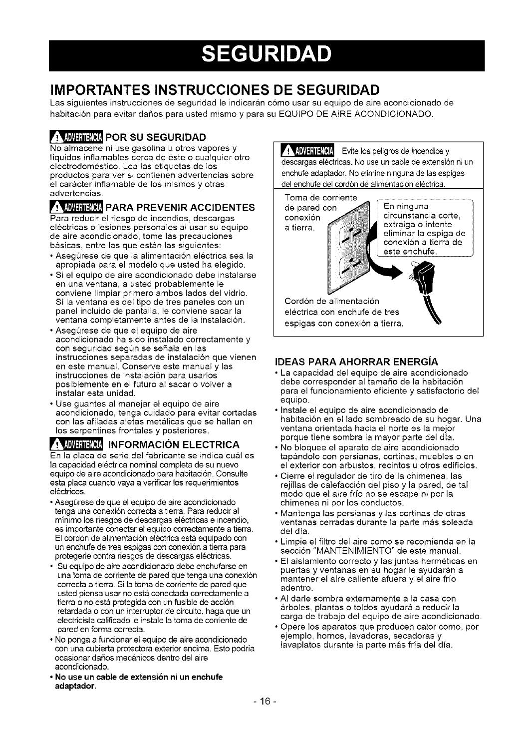
Evite los peligros de incendios y
descargas etectricas. No use un cable de extension ni un
enchufe adaptador. No elimine ninguna de Ias espigas
del enchufe det cordon de alimentacion electrica.
Toma de corriente
de pared con
conexion
a tierra.
En ninguna
circunstancia corte,
extraiga o intente
eliminar la espiga de
conexi6n a tierra de
este enchufe.
Cord6n de alimentacion _,
\
electrica con enchufe de tres
espigas con conexion a tierra.
IDEAS PARA AHORRAR ENERGiA
La capacidad del equipo de aire aoondicionado
debe corresponder a[ tamar_o de la habitaci6n
para el funcionamiento eficiente y satisfactorio del
equipo.
Instale el equipo de aire aoondicionado de
habitaoion en el lado sombreado de su hogar. Una
ventana orientada hacia el norte es la mejor
porque tiene sombra la mayor parte del dia.
No bloquee el aparato de aire acondicionado
tap&ndolo con persianas, oortinas, muebles o en
el exterior con arbustos, reointos u otros edificios.
Cierre el regulador de tiro de la chimenea, las
rejillas de calefaocion del piso y la pared, de tal
modo que el aire frio no se escape ni por la
ohimenea ni por los conductos.
Mantenga las persianas y las cortinas de otras
ventanas cerradas durante la parte mas soleada
del dia.
Limpie el filtro del aire como se recomienda en la
seccion "MANTENIMIENTO" de este manual.
El aislamiento correcto y las juntas hermeticas en
puertas y ventanas en su hogar le ayudaran a
mantener el aire caliente afuera y el aire frio
adentro.
AI darle sombra externamente a la casa con
arboles, plantas o toldos ayudara a reducir la
carga de trabajo del equipo de aire acondicionado.
Opere los aparatos que producen calor como, por
ejemplo, hornos, lavadoras, secadoras y
lavaplatos durante la parte mas fria del dia.
-16-
RESPETE TODOS LOS CODIGOS Y
REGLAMENTOS.
BAJO NINGUNA CIRCUNSTANCIA CORTE,
QUITE 0 EVITE EL USO DE LA CONEXION A
TIERRA DE ESTA CLAVIJA.
ESTE APARATO NECESITA SER CONECTADO A
TIERRA.
Se requiere una alimentaci6n electrica CA,
adecuadamente conectada a tierra con un fusible de
15A, de 60 Hz y de 230/208V. Se recomienda un
fusible de retardo o un disyuntor de circuito que
alimente solamente a este aparato.
NO USE CABLE ELECTRICO DE EXTENSION.
MI_TODORECOMENDADO DE CONEXION A
TIERRA
Por su propia seguridad este aparato debe
conectarse a tierra. Este aparato viene equipado
con un cable de alimentaci6n y una clavija de tres
terminales. Para reducir al maximo el peligro de
choque electrico, el cable debe estar conectado a
una conexi6n de pared con conexi6n a tierra, y esta
conexi6n debe hacerse de acuerdo con la Qltima
edici6n del C6digo Electrico Nacional (ANSI/NFPA
70), asi como con los c6digos y reglamentos
locales. Si no existe una conexi6n de pared
adecuada, el cliente tiene la responsabilidad y la
obligaci6n de mandar instalar,con un electricista
calificado, una conexi6n de pared adecuada de tres
terminales con conexi6n a tierra.
Peligrode choqueelectrico
Conecteen unaconexi6nde paredde3 terminales
Noquitela terminalde conexi6na tierra
Nouseadaptadores
Nousecableelectricode extensi6n
Si no sesiguenestasinstrucciones,puede
ocasionarsela muerte,un incendioo un cheque
electrico.
Cable de alimentaci6n
clavija dotada de conexi6n
a tierra de 3 terminales.
Toma de corriente
de pared con
conexi6n a tierra.
_cToenr emix?a_daetierra
I
Bajo ninguna circunstancia corte, quite o evite
el uso de la conexi6n a tierra de esta clavija.
Puede escoger entre los dos metodos abajo descritos de acuerdo a la forma del taburete de su ventana y su
preferencia.
UTILIZANDO LA RANURA "A"
Aprete el obturador usando 2 hoyos de tornillo, y
saque el cable electdco a traves de la ranura "A".
UTILIZANDO LA RANURA "B"
Aprete el obturador usando el hoyo izquierdo de
tornillo, y gire apropiadamente para sacar el cable
electrico a traves de la ranura "B".
O
-17-
REQUERIMIENTOS PARA
INSTALAClON
Su equipo de aire acondicionado se instalara en
ventanas estandar de doble panel con anchos de
abertura libre de 737 mm a 1041 mm (29 a 41
pulgadas). (Figura 1)
El marco inferior debe abrirse Io suficiente para
permitir una abertura vertical libre de 457 mm (18
pulgadas). Las rejillas desviadoras laterales y la
parte posterior del equipo de aire acondicionado
deben tener un espacio libre de aire para permitir
suficiente flujo de aire a traves del condensador
para asi eliminar el calor. La parte posterior de la
unidad debe quedar al aire libre, no dentro de un
edificio o garaje.
............._ ...................." Banda
kt
18" min. . Ventana
I, Relq)sa.l
II I ',,_'"_:_ J Rebajo
."1 m< -- Antepech°
I 21 f"-! Exterior
Pared in_tte;_!....... "_°°" Figura 1
SERVICIO ELECTRICO
Compruebe cual es la aIimentaci6n electrica que Ilega a
su domicilio. La alimentaci6n electrica disponible debe
ser la misma que se muestra en la placa del fabricante de
Ia unidad (clue se halla en el lado derecho del gabinete de
corriente alterna).
Todos los modelos estan equipados con un enchufe de
tres espigas para suministrar un servicio correcto y una
conexion a tierra segura y positiva. No cambie ei enchufe
de ninguna forma. No use un enchufe adaptador. Si su
toma de corriente de pared actual no puede usarse con el
enchufe del equipo, Ilame a un electricista calificado para
que efect0e Ias correcciones necesarias.
CONSERVE LA CAJA y este MANUAL DEL
PROPIETARIO para que le sirva como referencia en el
futuro. La caja es la mejor manera de conservar Ia unidad
durante ei invierno o cuando no esta en uso.
INSTALACION PIEZAS DE MONTAJE
A B C D E
F G H I J K
Figura 2
iTEM NOMBRE DE LAS PIEZAS CANTIDAD
A PANEL DE GUJA 2
B SOPORTE 2
C SOPORTE DE ANTEPECHO 2
D CONTRATUERCA 4
E TORNILLO: 25/64" 11
F TORNILLO: 1 3/ld' 7
G TORNILLO: 9/16" 5
H TORNILLO M 2
I BULON 2
J ClNTA DE ESPUMA 1
K ClNTA DE ESPUMA 1
L SOPORTE DE CERRADURA 1
M TUBO DE DRENAJE 1
HERRAMIENTAS REQUERIDAS
Para evitar el riesgo de lesiones personales, danos asu
propiedad, o danos al producto debido al peso de este
equipo y los fiIosa que seran expuestos:
El aireacondicionado del que se habIa en este manual
afirma peligro de peso excesivo.
Dos o mas personas se requiere para mover e instaIar ta
unidad. Para evitar heridas o agotamlento, use tecnicas
apropiadas para Ievntar y mover launidad.
Cuidadosamente inspecoione el lugar donde et aire
acondicionado sera puesto. Asegurese que el lugar
sostenga eIpeso de Iaunidad sobre un periodo de
tiempo prolongado.
Mantenga su aire acondicionado con cuidado. Use
guantes protectores cuando levante o mueva Ia unidad.
EVITE tas aletas filosas de metal en el serpentin
delantero y de atras.
Asegurese que el aire acondicionado no se caiga
durante tainstalacion.
Guantes apretados
Destornillador normal
Destornillador Phillips
Pinsas
Cuchillo filoso
Llave inglesa o Ilave abierta de 3/8"
Llave hexagonal de cubo y trinquete de 1/4 de
pulgada
Cinta para medir
Taladro electrico
Broca de taladro de 1/4"
-18-
INSTALAClON
Escoja un lugar que le permita Ilevar el aire frio al &rea
que desea. Las ventanas que se usen para la
instalaci6n deben tener la resistencia suficiente para
soportar el peso del equipo de aire acondicionado. Una
buena instalaci6n con atenci6n especial a la correcta
posici6n de la unidad disminuir& la probabilidad de que
sea necesario efectuar reparaciones.
Cuando se desea enfriar mas de una habitaci6n, la
instalaci6n es muy importante puesto que el aire frio no
dobla esquinas. Para enfriar sus habitaciones, el aire
frio debe desplazarse desde el equipo de aire
acondicionado en una trayectoria recta.
CONO INSTALARLO
_1 Saque los tornillos que aseguran el gabinete en
ambos lados yen la parte posterior.
Figura 3
_"_ Deslice la unidad sacandola de su gabinete
agarrando el asa del recipiente de la base y tirando
de ella hacia delante mientras sostiene el gabinete.
Figura 4
_J Corte la cinta de espuma (iTEM J) a la
extension apropiada.
Despegue el refuerzo y peguelo en el lado de abajo
del marco de la ventana.
O Inserte los panetes de guia (iTEM A) en Iaguia superior
y tas guias de marco deI equipo de aire acondicionado.
Sujete tas cortinas en la unidad con los tornillos (iTEM E)
iTEME
Guia mas baja
iTEME Figura 6
_[_4JAbra la ventana. Marque una linea en el centro de la
repisa de ia ventana entre los moldes de tope lateral de la
ventana. Fije sin apretar el soporte de antepecho (iTEM C)
al otro soporte (iTEM B) usando el bul6n (iTEM I) y Ia
contratuerca (iTEM D).
iTEM
iTEM I
"'¢_-_iTEM D
Figura 7
r_Fije el soporte de antepecho al antepecho a la
ventana usando los tornillos (iTEM F). Coloque
cuidadosamente el gabinete sobre la repisa de Ia ventana
y alinee la marca del centro en la parte frontal inferior con
Ia Iinea central marcada en Ia repisa de Ia ventana.
_Torniltopara metates y
contratuerca
Borde exterior del
_antepecho de la
ventana
(iTEM F)
Bul6n y contratuerca \ Figura 8
Soporte de antepecho
U Usando el tornillo M (iTEM H) y la contratuerca
(ITEM D), fije el soporte al orificio de carril del gabinete.
Use el primer orificio de carriI despues del soporte de
antepecho en el borde exterior del antepecho de ventana.
Apriete el bul6n y la contratuerca. Asegurese de que el
gabinete se incline hacia fuera 1/4 de gota usando el nivel.
CUIDADO: No perfore un orificio en el recipiente inferior.
La unidad esta disefiada para operar con apreximadamente
1/2 pulgada de agua en el recipiente inferior.
J Banda
Figura 5
Guia inferior
INTERIOR
Gabinete
EXTERIOR Figura 9
-19-
_1 Tire del marco inferior de la ventana hacia abajo
detras de ia guia superior hasta que se encuentre la guia
con el marco.
NOTA:
No tire del marco de la ventana tan hacia abajo que
restrinja el movimiento de las correderas. Fije eI
gabinete a la repisa de la ventana atornillando los
tornillos (iTEM F) a traves del gabinete en la repisa de
la ventana.
El gabinete debe instalarse 1/4 de gota de el niveI, hecia
abajo y hacia fuera.
Marcode
laventana
Qnta
de
espuma
/
Gabinet
Encuadre
cortina
"iTEMF
Figura 10
_"_ Extienda eI panel hasta Ilenar el hueco.
Fije cada panel guia en el marco de la ventana usando
dos tornillos (iTEM G). (Figura ! 1)
ITEM G
lowerGuide
Figura 11
_I'_ Se debe instalar el asa antes de fijar el frente
decorativo. (Figura 12)
Figura 12
_q_IDREANJE
En la parte posterior de la unidad de aire acondicionado hay
un orificio de drenaje. Seleccione un metodo de drenaje
segun las siguientes instrucciones:
Saque del recipiente de base la goma del odficio.
Conecte una manguera de drenaje de 9/16" de pulgada de
diametro intemo al tubo de drenaje como se muestra.
Conecte un codo de tubo de 9/16" de pulgada de diametro
interno al tubo de drenaje, conecte seguidamente una
manguera de drenaje de 9/16" de pulgada de diametro
interno al codo del tubo como se muestra. (El equipo de aire
acondicionado no viene con una manguera de drenaje.)
Manguera
de drenaje Manguera de drenaje
Figura 13
[] Deslice el chasis hacia el interior del gabinete.
(Figura 14)
CUIDADO: Con fines de seguridad, vuelva a
instalar los tornillos en los lados del gabinete.
Tornitlo
Cord6n de
etectrica
TorF_u ra 14
_! Corte la junta hermetica de espuma(JTEM K)
para que tenga la Iongitud apropiada e insertela
entre el marco superior y el marco inferior de la
ventana. (Figura 15)
Figura 15
E]_ Ajuste el asa antes de fijar el frente decorativo.
(Figura 16)
Enderence el kit de ventilacion como se indica,
halando hacia debajo de la parte _b Ilevandola en la
linea horizontal con la parte _.
_ Figura 16
- 20 -
1 / 1

Kenmore 000 BTU Multi-Room Air Conditioner Owner's manual

Category
Split-system air conditioners
Type
Owner's manual

Ask a question and I''ll find the answer in the document

Finding information in a document is now easier with AI

Ask the document