Page is loading ...

Ÿ
Ÿ
NOTE TO ASSEMBLER / INSTALLER:
Leave this manual with the consumer.
NOTE TO CONSUMER:
Keep this manual for future reference.
RECORD YOUR SERIAL # __________________
(see silver CSA label on main body of grill)
IMPORTANT:
Ÿ
Grill Information Center:
Call us first if you have any problem with this
product. We can help you with questions about
assembly and grill operation or if there are
damaged or missing parts when you unpack
this unit from the shipping box. Please call
before returning to the store.
1-877-934-7455
8am-4:30pm CST, Monday through Friday
Failure to comply with these instructions could
result in a fire or explosion that could cause
serious bodily injury, death or property damage.
Whether this grill was assembled by you or
someone else, you must read this entire manual
before using your grill to ensure the grill is
properly assembled, installed and maintained.
Use your grill at least 3 feet away from any
wall or surface. Use your grill at least 3 feet
away from combustible objects that can melt or
catch fire (such as vinyl or wood siding, fences
and overhangs) or sources of ignition including
pilot lights on water heaters and live electrical
appliances.
THIS GAS APPLIANCE IS DESIGNED FOR
OUTDOOR USE ONLY.
Combustion byproducts produced when using
this product contain chemicals known to the
State of California to cause cancer, birth de-
fects, or other reproductive harm.
Ÿ
Ÿ
Ÿ
Ÿ
Ÿ
WARNING
! !
OPERATOR'S MANUAL
Liquid Propane Gas (LPG)
Grill
Model 6306LP
Natural Gas (NG) Grill
Model 6306NG
Manual # P80157005A - Date:2006/02/27

2
The Grease Draining Tray and Grease
Receptacle must be visually inspected
before each grill use. Remove any grease
and wash Grease Draining Tray and
Grease Receptacle with a mild soap and
warm water solution. Failure to comply
with these instructions could result in
a grease fire or explosion that could
cause serious bodily injury, death or
property damage.
WARNING
! !
1.
2.
3.
WARNING
! !
Do not store spare LP cylinder
within 10 feet (3m) of this appliance.
Do not store or use gasoline or
other flammable liquids and
vapors within 25 feet (8m) of this
appliance.
When cooking with oil/grease, do
not allow the oil/grease to get
hotter 350°F (177°C).
Do not leave oil/grease unattended.4.
Do not store or use gasoline or other
flammable liquids or vapors in the
vicinity of this or any other appli-
ances.
An LP cylinder not connected for use
shall not be stored in the vicinity of
this or any other appliance.
1.
2.
WARNING
! !
Grill Installation Codes
The installation must conform with local codes or, in
the absence of local codes, with either the National
Fuel Gas Code, ANSI Z223.1/NFPA 54, or CAN/CGA-
B149.1, Natural Gas and Propane Installation Code.
LPG grill models must be used with
Liquid Propane Gas and the regulator
assembly supplied. Natural Gas models
must be used with Natural Gas only. Any
attempt to convert the grill from one fuel
type to another is extremely hazardous
and will void the warranty.
Never use your gas grill in a garage, porch,
shed, breezeway or any other enclosed area.
Never obstruct the flow of ventilation air
around your gas grill housing.
Never disconnect the gas regulator or any gas
fitting while your grill is lit. A lit grill can ignite
leaking gas and cause a fire or explosion which
could result in property damage, personal in-
jury or death.
Keep gas regulator hose away from hot
grill surfaces and dripping grease. Avoid
unnecessary twisting of hose. Visually in-
spect hose prior to each use for cuts, cracks,
excessive wear or other damage. If the hose
appears damaged do not use the gas grill.
Call:1-877-934-7455 for an authorized replace-
ment hose.
•
WARNING
!
!
•
•
•
•
1.
2
3.
4.
If you smell gas:
Shut off gas to the appliance.
Extinguish any open flame.
Open lid.
If odor continues, keep away from
the appliance and immediately call
your gas supplier or your fire
department.
DANGER
! !
Leaking gas may cause a fire or
explosion which could result in property
damage, personal injury or death.
Table of Contents
Primary Safety Warnings.....................................1-3
Pre-Assembly Instructions.......................................3
Part Diagrams and Lists...................................4-9
Assembly Instructions..........................................10-16
Rotisserie Assembly Instruction......................17-18
Use & Care Instructions:
• Gas Safety and Leak Tests....................19-22
• Lighting Instructions.....................................23-24
• Troubleshooting...................................................24
• Cleaning and Maintenance........................25-26
• Cooking Guide..............................................A1-A4
• Frequently Asked Questions.....................A5-A6
Warranty Terms........................................Back Cover

3
Pre-Assembly Instructions For Your Safety
Tools Required for Assembly include:
protective work gloves
protective eyewear
While it is possible for one person to unpack this gas
grill, obtain assistance from another person when
handling the large pieces.
Use the Hardware and Part Diagrams to ensure all
items are included and free of damage.
Do not assemble or operate the grill if it appears
damaged. If there are damaged or missing parts
when you unpack the shipping box or you have
questions during the assembly process, call the:
To expedite the assembly process follow these
general guidelines:
•
•
Grill Information Center 1-877-934-7455
8am-4:30pm CST, Monday through Friday
Phillips Head Screwdriver
•
Spiders and small insects can spin webs and
nest in the grill Burner Tubes during transit and
warehousing which can lead to a gas flow
obstruction resulting in a fire in and around the
Burner Tubes. This type of "FLASHBACK FIRE"
can cause serious grill damage and create an
unsafe operating condition for the user.
To reduce the chance of FLASHBACK
FIRE you must clean the Burner Tubes
as follows before initial use.
Also do this at least once a month in summer
and fall or whenever spiders are active in your
area, and if your grill has not been used for an
extended period of time.
CAUTION
! !
Failure to comply with these instructions may
result in a hazardous situation which, if not
avoided, may result in injury.
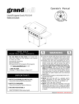
METHOD 1: Bend a stiff wire or wire coat
hanger into a small hook as shown and run
the hook through the Burner Tube and inside
the Burner several times to remove debris.
TO CLEAN BURNER TUBE, INSERT HOOK
HERE
METHOD 2: Use a bottle brush with a flexible
handle and run the brush through the Burner
Tube and inside the Burner several times to
remove any debris.
METHOD 3: Use an air hose to force air
through each Burner Tube. The forced air
should pass debris or obstructions through
the Burner and out the Ports.
9
Burner
Foot
WARNING
! !
For safe operation ensure the Gas Valve Assem-
bly Orifice is inside the Burner Tube before using
your grill. See figure. If the Orifice is not inside
the Burner Tube, lighting the Burner may cause
explosion and/or fire resulting in serious bodily
injury and/or property damage.
Orifice Burner Tube
Gas Valve Assembly
Remove the screws from the rear of each Main
Burner using a Phillips Head Screwdriver.
Carefully lift each Burner up and away from the
Gas Valve Orifice.
Check and clean Burner/Venturi Tubes for insects
and insect nests. A clogged tube can lead to a fire
beneath the grill.
Refer to the figure below and perform one of
these 3 cleaning methods:
1.
2.
3.
4.

4
PART#PART DESCRIPTIONQTYPURPOSE OF PART
P06020005AHardware Pack 1For use in assembly (For LPG & NG model)
S112G04081Phillips Head Screw 1/4"x1/2"8
S142G03061
Countersink Flat Head Screw
3/16"x3/8"
8
S112G04081Phillips Head Screw 1/4"x1/2" 16Install Cart Bottom Shelf and Casters
S112G03061Phillips Head Screw 3/16"x3/8" 4
S313G03061Flange Nut 3/16" 6
S142G03061
Countersink Flat Head Screw
3/16"x3/8"
2
S112G03041Phillips Head Screw 3/16"x1/4" 4
P00201001CDoor Handle2
S112G03061Phillips Head Screw 3/16"x3/8" 4
S313G03061Flange Nut 3/16" 4
S112G03061Phillips Head Screw 3/16"x3/8" 4
S172M04101Self Tapping Screw M4x10mm 1
S112G04191Phillips Head Screw 1/4"x1-3/16" 4
S313G03061Flange Nut 3/16" 4
P05507031ELighting Stick1
S112G04081Phillips Head Screw 1/4"x1/2" 8Install Side Shelf Brackets
S112G04081Phillips Head Screw 1/4"x1/2" 8
S313G04081Flange Nut 1/4" 8
S313G04081Flange Nut 1/4" 2Install Tool Holder and Tool Hooks
S112G03061Phillips Head Screw 3/16"x3/8" 2
S313G03061Flange Nut 3/16" 2
P05536001PHose Holder 1
S112G03061Phillips Head Screw 3/16"x3/8" 2
S313G03061Flange Nut 3/16" 2
P05536001PHose Holder 1
S233G05461Wing Bolt 5/16"x4-1/2"1Secures Gas Tank
Already installed in Tank Hole of Cart Bottom Shelf
Install Regulator Assembly (For LPG Model only)
Install Side Shelf and Side Burner Frame
Attaches NG Regulator Assembly to Right Cart
Panel (For NG model only)
Install Caster Seats
Install Right and Left Door
Install Door Bracket, Grill Bowl and Lighting Stick
Install Cart Rear Panel, Door Stop Plate and Door
Handles
Hardware Pack Parts List for Models 6306LP & 6306NG

Phillips Head Screw
1/4" x 1/2"
Qty. 40
Part # S112G04081
Lighting Stick
Qty. 1
Part # P05507031E
Scale 1:2
Phillips Head Screw
3/16" x 1/4"
Qty. 4
Part # S112G03041
Flange Nut 3/16"
Qty. 16
Part # S313G03061
Phillips Head Screw
1/4" x 1-3/16"
Qty. 4
Part # S112G04191
Self Tapping Screw
M4 x 10mm
Qty. 1
Part # S172M04101
Countersink Flat Head Screw
3/16" x3 /8"
Qty. 10
Part # S142G03061
Flange Nut 1/4"
Qty. 10
Part # S313G04081
Phillips Head Screw
3/16" x 3/8"
Qty. 14
Part # S112G03061
5
* Two Batteries/AA included in the Hardware Pack.
Door Handle
Qty. 2
Part # P00201001C
Hardware Pack for Models 6306LP & 6306NG
Hardware already installed in Tank Hole of Cart
Bottom Shelf
Wing Bolt 5/16"x4-1/2"
Qty. 1 (LPG model)
Part # S233G05461
Scale 1:2
Hose Holder
Qty. 1
Part # P05536001P
Scale 1:2

6
70
54
6A
57
4
34
37
67
77
78
76
68
39
41
42
38
66
64
80
79
62
72
71
58
36
56
35
59
44
11
16
15
33
31
32
55
30
29
19
28
27
13
12
9
14
43
17
20
10
3
6B
7
5
2
1
65
73
75
74
69
70
15
16
61
18
21
22
60
26
25
63
65
8
81
40
(NG Only)
(NG Only)
(NG Only)
51
38
53
50
46
45
47
52
24
23
48
49
82
83
84
Parts Diagram for Models 6306LP & 6306NG

7
KEYDESCRIPTIONPART # QTY
1LidP0011920MA
1
2
Temperature GaugeP00601061A1
3
Lid HandleP00205068B1
4
Protective PadP05518011I4
5
Cooking Rack/Secondary
P01517004B
1
6ACooking GridP01604030A2
6BCooking GridP01604029A1
7Burner/MainP02008024A6
8Smoker BoxY04600021
9Savor Plates®P01708033B5
10Savor Plates® Bracket, FrontP03328015A6
11Savor Plates® Bracket, RearP03328017A6
12Burner BracketP02211184A1
13Grease Tray Heat Shield,UpperP06904045C1
14Side Shelf, LeftP01106005A1
15Side Shelf Bracket,Left Front/Right RearP01206005F2
16Side Shelf Bracket,Left Rear/Right FrontP01106005F2
17Bowl Panel, LeftP0072067PC1
18Bowl Panel, RightP0072167PC1
19Grease Draining PlateP06902008C2
20Bowl Wind ShieldP06906039C2
21Lid HingeP05501020A2
22Back Burner Wind ShieldP06905037B1
23Back Burner AssemblyY03100251
24Back Burner ElectrodeP02610005B1
Back Burner Orifice(LPG)P06531012A1
Back Burner Orifice(NG)P06531013A1
26Back Burner Extension TubeP03717039B1
27Bowl Panel, RearP0072567BC1
28Bowl Panel, FrontP0073863BC1
29Gas Collector Box with ElectrodeP02609007B6
30Electric Wire SetP02615089A1
31Grease Tray Heat Shield,LowerP06903047B1
Gas Valve/Manifold Assembly(LPG)Y00603531
Gas Valve/Manifold Assembly(NG)Y00603541
33Name PlateP00417005G1
34Control Panel, UpperP02910698S1
Control Panel, Extension(LPG)P02910771A1
Control Panel, Extension(NG)P02910761F1
36Control Panel, LowerP02910751A1
37Control Knob SeatP03415014S7
38Control Knob SpringP05504021A8
39Control Knob for Main Burners P03411383S6
40Control Knob for Back BurnerP03411373S1
41Electric Ignitor, 6-portP02502145C1
42Electric Ignitor, 2- portP02502192C1
43Tool HolderP05209004B1
44Tool HooksP05514131F3
45Side Burner LidP01127004B1
46Side Burner FrameP01108012B1
47Side Burner BodyP01108011B1
48Side Burner Pot SupportP00805010B1
49Side BurnerP02002012A1
50Side Burner ElectrodeP02614007C1
51Control Knob for Side Burner P03401043S1
52Hose Holder P05536001P1
25
32
35
Parts List for Models 6306LP & 6306NG

8
KEYDESCRIPTIONPART # QTY
53Side Burmer Control Knob SeatP03408053S1
Side Burner Gas Valve(LPG)Y00603491
Side Burner Gas Valve(NG)Y00603501
55Side Burner Connection HoseP03705029F1
56Grease Tray HandleP00213007B1
57Grease TrayP02717433C1
58Bowl Support Bracket, LeftP01301006B1
59Bowl Support Bracket, RightP01302006B1
60Rear Wind Shield, UpperP06906040C1
61Rear Wind Shield, LowerP0075202BC1
62Door Hinge Bracket, LeftP03302014A1
63Door Hinge Bracket, RightP03302015A1
64Cart Side Panel, LeftP07602020A1
Cart Side Panel, Right (LPG)P07603021A1
Cart Side Panel, Right (NG)P07603020A1
66Door BracketP01316005B1
67Door MagnetP05523001K4
67Door Stop PlateP05510014U1
68Cart Rear PanelP07701056A1
Cart Bottom Shelf (LPG)P01009038C1
Cart Bottom Shelf (NG)P01009039C1
71Caster Seat, Left FrontP05327027E1
72Caster Seat, Left Rear P05327029E1
73Caster Seat, Right Front P05327028E1
74Caster Seat, Right Rear P05327030E1
75Caster, 2.5 in., with BrakeP05117006E4
76Door HandleP00201001C2
77Door, LeftP04302035A1
78Door, RightP04303035A1
79Regulator with Hose (LPG)P03601032A1
80Lighting StickP05507031E1
81Side Burner Extension Hose (NG only)P03705082F1
82Regulator Assembly (NG)Y00800071
83 Hose, 12ft.(NG)P03704001A 1
84Side Burner Wind ShieldP06908003C1
Rotisserie AssemblyY02501091
Hardware Pack (For LPG & NG model)P06020005A1
Operator's ManualP80157005A1
54
70
65
To obtain the correct replacement parts for your gas grill, please refer to the part numbers in this parts
list. The following information is required to ensure you receive the correct parts:
1. Model and Serial Number (see CSA label on grill)
2. Part Number
3. Part Description
4. Quantity of parts needed
Important: Use only factory authorized parts. The use of any part that is not factory authorized can be
dangerous and will also void your product warranty. Keep this Operator's Manual for convenient referral
and for part replacement.
For the repair or replacement parts you need:
Call our Grill Information Center at 1-877-934-7455
Parts List for Models 6306LP & 6306NG

Y0250109 Rotisserie Assembly Parts Diagram
9
Hardware for Rotisserie
Grill Information Center: If you have questions about assembly or grill operation, or if there are damaged
or missing parts when you unpack this unit from the shipping box, call us 8:00 am - 4:30 pm CST,
Monday through Friday at: 1-877-934-7455
5
2
4
3
2
1
2
6
7
8
9
10
11
Y0250109 Rotisserie Assembly Parts List
KEY
PART#
DESCRIPTION
QTY
Rot. Bushing
Rot. 3/8"x1/2" Thumbscrew
Rot. Collar
Rot. Spit
Rot. Holding Fork
Rot. Handle
Rot. Motor Bracket
Rot. Motor/AC
Rot. #10-24x3/4" UNC Screw
Rot. Washer
Rot. #10-24 Nut
1.
2.
3.
4.
5.
6.
7.
8.
9.
10.
11.
1
3
1
1
2
1
1
1
2
2
2
P05508092F
S196G06084
P05508091F
P05508163F
P05508090F
P05508076E
P03307028A
P07101010A
S112G10124
S411G03084
S362G10124
Rot. Screw#10-24x3/4"
UNC
Qty. 2
Part# S112G10124
Rot. Thumbscrew
3/8"x1/2"
Qty. 3
Part# S196G06084
Rot. Washer
Qty. 2
Part# S411G03084
Rot. Nut#10-24
Qty. 2
Part# S362G10124

10
Assembly Instructions
Remove all cart parts, hardware, and Grill Head from shipping boxes. Raise the Grill Lid and remove all packed
components. Use the parts list to check that all necessary parts have been included.
Assemble the gas grill on a protective work surface to avoid scratching grill surfaces. Inspect your grill for damage
as you proceed. Do not assemble or operate your grill if it appears damaged.
Place Left Cart Side Panel (parts are labeled L or R) upside down on the cardboard work
surface, reverse side of panel facing up. Install the Caster Seats (A,B) to Left Cart Side Panel
using 4 Countersink Flat Head Screws 3/16'’ x 3/8'’ and 4 Phillips Head Screws 1/4'’ x 1/2'’
Repeat for Right Cart Side Panel, install the Caster Seats (C,D) using 4 Countersink Flat
Head Screws 3/16'’ x 3/8'’ and 4 Phillips Head Screws 1/4'’ x 1/2'’.
1
Install Caster Seats
2
Install Cart Bottom Shelf and Casters
Phillips Head Screw
1/4" x 1/2"
Qty. 16
Part # S112G04081
Phillips Head Screw
1/4" x 1/2"
Qty. 8
Part # S112G04081
Countersink Flat Head Screw
3/16"x3/8"
Qty. 8
Part # S142G03061
A
B
Cart Side Panel, Left
3/16" x 3/8"
Countersink Flat Head Screw
1/4" x 1/2"
Phillips Head Screw
71
Cart Side Panel, Left
Cart Side Panel, Right
72
72
71
Cart Bottom Shelf - Tank Hole
Install Cart Bottom Shelf to Left and Right Cart Side Panel with 8 Phillips Head Screws 1/4" x 1/2".
(NOTE: Be sure that the tank hole is positioned to the right).
Install the 4 Casters onto Caster Seats as shown.

Install the Top Left Door Hinge Bracket to the Left Cart Side Panel with 2 Phillips Head Screws 3/16'’
x 3/8'’ and 2 Flange nuts 3/16'’. Do not tighten both screws immediately.
Insert Bottom Left Door Hinge into Bottom Left Door Hinge Bracket. Then align Top Door Hinge and
insert into the hole on Top Left Door Hinge Bracket and tighten securely the 2 screws.
Repeat both steps for Right Door.
Install Right and Left Door
Install the Cart Rear Panel between the Cart Side Panels
using 4 of 3/16” x 3/8” Phillips Head Screws and 4 of 3/16”
Flange Nuts.
Install Cart Rear Panel, Door Stop Plate and Door Handles
Install the Door Stop Plate to Bottom Shelf using 2 Countersink
Flat Head Screws 3/16” x 3/8” and 2 Flange Nuts 3/16” .
Install the Door Handles to Doors using 4 Phillips Head
Screws 3/16” x 1/4”.
Flange Nut 3/16"
Qty. 6
Part # S313G03061
Countersink Flat Head Screw
3/16"x3/8"
Qty. 2
Part # S142G03061
Phillips Head Screw
3/16" x 3/8"
Qty. 4
Part # S112G03061
Flange Nut 3/16"
Qty. 4
Part # S313G03061
11
Phillips Head Screw
3/16"x1/4"
Qty. 4
Part # S112G03041
Top Door
Hinge
Top Left
Door Hinge
Bracket
Phillips Head Screw
3/16" x 3/8"
Qty. 4
Part # S112G03061
3
4
Door Handle
Qty. 2
Part # P00201001C
Scale 1:2

Self Tapping Screw
M4 x 10mm
Qty. 1
Part # S172M04101
5
5
Install Door Bracket, Grill Bowl and Lighting Stick
6
Install Side Shelf Brackets
Flange Nut 3/16"
Qty. 4
Part # S313G03061
Phillips Head Screw
3/16" x 3/8"
Qty. 4
Part # S112G03061
Phillips Head Screw
1/4" x 1/2"
Qty. 8
Part # S112G04081
Remove cooking components from Grill Head. With an
assistant, lift and position Grill Head on the Cart. Tighten
securely using 4 Phillips Head Screws 1/4”x1-3/16”.
Install the Door Bracket between the Left and Right Cart
Side Panel using 4 of 3/16” x 3/8” Phillips Head Screws
and 4 Flange Nuts 3/16”.
Install the Lighting Stick to Left Bowl Panel using 1
Self Tapping Screw M4 x 10mm.
12
Attach the Side Shelf Bracket (A) to the Rear of Right Bowl Panel.
Attach the Side Shelf Bracket (B) to the Front of Right Bowl Panel.
Tighten securely using Phillips Head Screws 1/4” x 1/2”.
Repeat for Left Side Shelf Brackets.
Side Shelf Bracket, (A)
Side Shelf Bracket, (A)
Side Shelf Bracket, (B)
Side Shelf Bracket, (B)
IMPORTANT: Lock 4 casters.
Lighting Stick
Qty. 1
Part # P05507031E
Scale 1:2
Phillips Head Screw
1/4" x 1-3/16"
Qty. 4
Part # S112G04191

Place the Side Shelf over the Left Side Shelf Brackets and
Side Burner Frame over the Right Side Shelf Brackets.
Tighten securely using Screws and Nuts provided.
7
Install Side Shelf and Side Burner Frame
Phillips Head Screw
1/4" x 1/2"
Qty. 8
Part # S112G04081
Flange Nut 1/4"
Qty: 8
Part # S313G04081
Install Grease Tray
13
Install Grease Tray Heat Shield on Grease Tray.
From the front of the grill, slide the assembled Tray
side tabs over the side rails underneath the Grill Bowl.
Grease Tray
Grease Draining Tray
Heat Shield
8

9
14
Flange Nut 1/4"
Qty: 2
Part # S313G04081
Install the Towel Bar and Tool Hooks using 2 Flange Nuts 1/4”
as shown.
Install Tool Holder and Tool Hooks
Install the Connection Hose with Brass Nut attached to the
Gas Fitting and tighten securely.
10
Install Connection Hose
Connection Hose

15
Hose Holder
Qty. 1
Part # P05536001P
Scale 1:2
12
Flange Nut 3/16"
Qty. 2
Part # S313G03061
Phillips Head Screw
3/16" x 3/8"
Qty. 2
Part # S112G03061
11
Hose Holder
Qty. 1
Part # P05536001P
Scale 1:2
Phillips Head Screw
3/16" x 3/8"
Qty. 2
Part # S112G03061
Place the Natural Gas regulator hose through the hole on Right
Cart Side Panel. Tighten securely using Brass Nut found in
the NG Regulator. See Fig. 1.
Secure the Natural Gas Regulator Hose onto Hose Holder
on Cart Rear Panel using the Hose Holder, Screws and
Nuts provided. See Fig. 2.
Install Regulator Assembly (For NG model only)
Figure 2
Place the Regulator with Hose ( LPG) inside the cart
through the opening above Cart Rear Panel. Secure
the Regulator with Hose ( LPG) onto Cart Rear Panel
using the Hose Holder, Screws and Nuts provided.
Install Regulator Assembly (For LPG model only)
Flange Nut 3/16"
Qty. 2
Part # S313G03061
LPG Regulator
Cart Rear Panel
Hose
Hose Holder
NG Regulator
Cart Rear Panel
NG Regulator
Connection Hose
Cart Side Panel,
Right
Brass Nut
Figure 1
Hose Holder
Hose
12
11

16
WARNING
!
Failure to read and follow the Use and Care
Instructions could result in a fire or explosion
that could cause serious bodily injury, death or
property damage.
!
Final Grill Assembly Step
When you have finished assembling your
grill be sure that all screws are tightened
for safe operation of your grill.
Install Ignitor Battery
13
Unscrew Ignitor Cap from Control Panel.
Place supplied AA battery into the Ignitor
Slot with positive pole facing you.
Position the Cap and Spring over the AA
battery and tighten onto Control Panel.
With the assistance of another person,
perform this Electrode Check before
proceeding.
14
Be sure all Control Knobs are set to
"OFF" and open the Grill Lid.
Have your assistant stand behind to the
right of the grill and look toward the front
of the grill bowl. Never put your face
inside the Grill Head.
Press the Ignitor Cap. You should hear
a "clicking" sound. Your assistant should
see a blue spark within each Gas
Collector Box. If a spark is present the
Electrode Tips are properly positioned.
If no spark is seen, the Spark Gap
needs to be adjusted as follows:
This test will ensure that the Spark Electrode Tips
are properly positioned so your grill lights easily
and properly.
•
•
•
Using an adjustable wrench, loosen the
Inside Nut until the Gas Collector Box can
be turned upward.
If the gap between the Spark Elec-
trode Tip and Receiver is more than
3/16" use long nose pliers to gently
squeeze the Gas Collector Box to
narrow gap.
Return the Gas Collector Box to its
original position, secure the Inside Nut
and try the Electrode Check again. If no
"clicking" sound is heard:
AA Battery may be installed back-
wards.
Electric wires may be loose. Remove
the AA Battery and inspect the Ignitor
Junction Box found behind the Control
Panel and reconnect any loose wires.
Side Burner Electrode Check
15
Open side burner lid. Remove plastic
shipping band from burner and pot
support.
Push and turn side burner Control Knob
to HIGH. Look for spark between tip of
electrode and burner.
If you don't see a spark from side burner elec-
trode, adjust gap between electrode and
burner surface to 3/16 in.
Spark Gap
Gas Collector Box
Spark Electrode Tip
Spark Receiver
Inside Nut
Install Cooking Components
16
Place the Savor Plates
®
above the
Burners.
Place the Cooking Grids on the ledge
above the Savor Plates
®
.
Place the Secondary Cooking Rack on
the slots on either side of the Grill
Bowl.
Savor Plates
Cooking Grids
Secondary Cooking Rack
®
-
-
Ignitor Slot
AA Battery
Ignitor Cap
+
_
Spring
15

Rotisserie Assembly Instructions
17
1.
Remove all components from the carton.
Attach the Motor Bracket on the outside of the left grill bowl panel. Align the two holes of the Bracket
with the holes on the grill bowl. Tighten securely using two Screws #10-24x3/4" UNC, Plain Washers
and Nuts provided.
2.
Slide the Holding Forks onto each end of the Rotisserie Spit. Adjust spacing between Holding
Fork to accommodate your food, then tighten the Thumbscrews to keep the Holding Forks in
position. Slide the Collar and Bushing onto the the threaded end of the Spit. Do not tighten the
Collar Thumbscrew until the Rotisserie is placed into your grill.
3.
Rot. Screw #10-24x3/4" UNC
Qty. 2
Part# S112G10124
Rot. Washer
Qty. 2
Part# S411G03084
Rot. Nut #10-24
Qty. 2
Part# S362G10124
Washer#10-24 Nut.
Rot. Screw#10-24x3/4"
UNC with washers
and nuts
Outside of left grill
bowl panel
Motor Bracket
Thumbscrew
3/8"x1/2"
Collar
Holding Forks
Thumbscrew
3/8"x1/2"
Bushing
Spit
Handle
Rot.Thumbscrew 3/8"x1/2"
Qty. 3
Part# S196G06084

18
The Bushing and Collar must always be used with this Rotisserie.
BEFORE rotisserie cooking you will need to remove the Cooking Grid(s) and possibly the Savor Plates
®
from your grill. When rotisserie cooking place a Cooking Pan under the food to be cooked. This will
capture the drippings and keep your grill clean of excess grease which could cause a fire. Use caution
when moving a Cooking Pan containing hot oils.
Install the AC (alternating current) Rotisserie Motor onto the Motor Bracket as shown below. Be sure
the Motor attaches to the Bracket with the electrical cord down. This installation ensures that once
the Spit is inserted into the Motor it will also rest securely into the slot of your grill bowl.
4.
Insert the assembled Rotisserie into the Motor as shown below. The Motor should be on the left side
of your grill. Place the Bushing into the slot opening on the Right side of your grill bowl, then tighten
the Collar Thumbscrew to the right of the Bushing. The Collar will stabilize the Rotisserie during the
cooking process and the Bushing allows the Rotisserie Spit to turn smoothly. Plug the Rotisserie into
an outlet and turn on to test.
5.
Rotisserie Motor
Motor Bracket
Rotisserie Spit must rest securely
into the slot of your grill bowl.
Handle
Bushing
Collar
Thumbscrew
Spit
Holding Forks
Thumbscrew
Motor

CORRECT LP GAS TANK USE
LP Gas grill models are designed for use with a
standard 20 lb. Liquid Propane Gas (LP Gas) tank,
not included with grill. Never connect your gas grill to
an LP Gas tank that exceeds this capacity. A tank of
approximately 12 inches in diameter by 18-1/2 inches
high is the maximum size LP Gas tank to use. You
must use an "OPD" gas tank which offers a listed
Overfill Prevention Device. This safety feature
prevents tank from being overfilled which can cause
malfunction of LP Gas tank, regulator and/or grill.
Never connect an unregulated LP gas tank to your
gas grill. The gas regulator assembly supplied with
your gas grill is adjusted to have an outlet pressure
of 11" water column (W.C.) for connection to an LP
gas tank. Only use the regulator and hose assembly
supplied with your gas grill. Replacement regulators
and hose assemblies must be those specified by
the Manufacturer.
Have your LP Gas dealer check the release valve
after every filling to ensure it remains free of defects.
Always keep LP Gas tank in upright position.
Do not subject the LP Gas tank to excessive heat.
Never store an LP Gas tank indoors. If you store
your gas grill in the garage always disconnect the
LP Gas tank first and store it safely outside.
LP Gas tanks must be stored outdoors in a well-
ventilated area and out of the reach of children.
Disconnected LP Gas tanks must not be stored in a
building, garage or any other enclosed area.
The regulator and hose assembly can be seen after
opening the doors (if applicable) and must be
inspected before each use of the grill. If there is
excessive abrasion or wear or if the hose is cut, it
must be replaced prior to using the grill again.
Never light your gas grill with the lid closed or
before checking to ensure the burner tubes are fully
seated over the gas valve orifices.
Never allow children to operate your grill. Do not
allow children or pets to play near your grill.
The LP Gas tank must be constructed and marked
in accordance with the Specifications for LP-Gas
Cylinders of the U.S. Department of Transportation
(D.O.T.) or the National Standard of Canada, CAN/
CSA-B339, Cylinders, Spheres and Tubes for
Transportation of Dangerous Goods and Commis-
sion, as applicable.
The LP Gas tank must have a shutoff valve,
terminating in an LP Gas supply tank valve outlet,
that is compatible with a Type 1 tank connection
device. The LP Gas tank must also have a safety
relief device that has a direct connection with the
vapor space of the tank.
The tank supply system must be arranged for vapor
withdrawal.
The LP Gas tank used must have a collar
to protect the tank valve.
WARNING
!!
Do not store a spare LP-Gas tank under or near
this appliance.
Never fill the tank beyond 80 percent full; and
If the information in "(a)" and "(b)" is not followed
exactly, a fire causing death or serious injury may
occur.
A.
B.
C.
•
•
•
WARNING
! !
Never use your gas grill in a garage, porch, shed,
breezeway or any other enclosed area.
Never obstruct the flow of ventilation air around
your gas grill housing.
Use of alcohol or drugs may impair the ability to
assemble and operate the appliance.
Keep fire extinguisher readily accessible. In the
event of a oil/grease fire, do not attempt to
extinguish with water. Use type B extinguisher
or smother with dirt, sand or baking soda.
In the event of rain, cover the grill and turn off
the burner and gas supply.
Use your grill on a level, stable surface in an
area clear of combustible materials.
Do not leave grill unattended when in use.
Do not move the appliance when in use.
Allow the grill to cool before moving or storing.
Do not use your grill as a heater.
This grill is not intended to be installed in
or on recreational vehicles and/or boats.
19
USE AND CARE INSTRUCTIONS
Use your grill at least 3 feet away from any
wall or surface. Use your grill at least 3 feet
away from combustible objects that can melt
or catch fire (such as vinyl or wood siding,
fences and overhangs) or sources of ignition
including pilot lights on water heaters and live
electrical appliances.

20
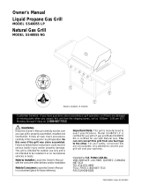
If growing bubbles appear do not use or move
the LP Gas tank. Contact an LP Gas Supplier
or your fire department!
WARNING
!
!
NOTE about LP Gas Tank Exchange Programs
Many retailers that sell grills offer you the option of
replacing your empty LP Gas tank through an ex-
change service. Use only those reputable exchange
companies that inspect, precision fill, test and certify
their tanks. Exchange your tank only for an OPD safety
feature-equipped tank as described on page19 of this
manual.
Ÿ
How to Leak Test your LP Gas Tank
LP Gas Model only:
Secure a 20lb LP Gas Tank to Gas Grill
Turn your LP Gas Tank Valve clockwise to the
closed or OFF positon.
Place LP Gas tank into tank hole on bottom shelf.
Install the tank so the Tank Valve faces the rear
right corner of cabinet.
Screw the Wing Bolt in to secure the gas tank.
Use a clean paintbrush and a 50/50 mild soap and
water solution.
Brush soapy solution onto LP Gas tank in the
areas indicated by the arrows. See diagram.
If growing bubbles appear do not use or move the
LP Gas tank. Call an LP Gas Supplier or your Fire
Department.
All leak tests must be repeated each time your LP
Gas tank is exchanged or refilled.
When checking for gas leaks do not smoke.
Do not use an open flame to check for gas leaks.
Your grill must be leak tested outdoors in a well-
ventilated area, away from ignition sources such as
gas fired or electrical appliances. During the leak test,
keep your grill away from open flames or sparks.
Do not use household cleaning agents. Damage to
gas assembly components can result.
Ÿ
Ÿ
Ÿ
Ÿ
Ÿ
Ÿ
Ÿ
For your safety:
Leak test new and exchanged LP Gas tanks BEFORE
connecting one to your grill.
Always keep new and exchanged LP Gas tanks in an
upright position during use, transit or storage.
Wing Bolt 5/16"x4-1/2"
Qty. 1 (LPG model)
Part# S233G05461
Scale 1:2
USE AND CARE INSTRUCTIONS
/