Page is loading ...

CIB 3023
(Z7309H01B) 10-Button Hands-Free
Answer on Intercom (HFAI) Voice
Terminal (3161)
CIB 3023
Comcode 105-253-025
Issue 3

CIB 3023
(Z7309H01B) 10-Button Hands-Free Answer on
Intercom (HFAI) Voice Terminal (3161)
The 10-Button HFAI Voice Terminal (Figure 1) allows you to program
and use all the custom features that your communications system pro-
vides. It also permits you to answer and talk on announced intercom
calls without lifting your handset. Included with these instructions for ins-
talling your HFAI Voice Terminal is a User’s Card with instructions for
using the voice terminal. Keep it handy for quick reference.
Handset jack
FIGURE 1 The 10-Button HFAI Voice Terminal
Assembling Your Voice Terminal
●
●
●
●
Your 10-Button HFAI Voice Terminal comes with the following com-
ponents:
Voice terminal body
Handset (with handset cord attached)
Modular voice terminal cord
Plastic desk stand/wall mount (with rubber feet attached)
The pieces of the desk stand/wall mount come attached to one another
(Figure 2), with the names Base, Desk Support, and Wall Support
iss 3, cib3023-1

imprinted on the appropriate pieces. Separate instructions follow for
each application.
1
2
3
Desk
support
Runner
Wall
support
Base
FIGURE 2 Unassembled Desk Stand/Wall Mount
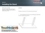
DESK STAND ASSEMBLY
Break the pieces of the desk stand/wall mount away from the runner.
Discard the runner.
Find the stand pieces labeled Base and Desk Support. File the rough
edges off these pieces where they were attached to the runner.
Insert the tabs labeled A and B on the desk support into the slots
labeled A and B on the base (Figure 3).
Desk support
Base
FIGURE 3 Assembling the Desk Stand
iss 3, cib3023-2

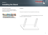
4
Turn the voice terminal upside down, and position the stand on the
voice terminal so that the stand’s mounting slots (Figure 4A) fit just
below the voice terminal’s mounting tabs (Figure 4B).
Mounting
slots
Mounting
tabs
A
B
Locking
tab
Stand attached
to voice terminal
(bottom view)
5
6
7
FIGURE 4 Attaching the Voice Terminal to the Desk Stand
Gently slide the stand upward so that the voice terminal tabs fit
securely in the three mounting slots on the stand (Figure 4C). Press
down on the stand to secure the locking tab.
Thread one end of the modular voice terminal cord between the base
of the desk stand and the bottom of the voice terminal, and plug it
into the jack labeled Line on the bottom of the voice terminal.
Turn the voice terminal right side up, and place the handset in the
cradle (Figure 5).
iss 3, cib3023-3

Desk support
FIGURE 5 10-Button HFAI Voice Terminal Attached to the Desk Stand
8
9
10
Check to see that one end of the handset cord is attached to the
handset. If it is not, plug it into the handset now.
Plug the other end of the handset cord into the jack on the middle
front of the voice terminal.
Plug the other end of the modular voice terminal cord into the build-
ing wiring connection, which is either a modular voice terminal exten-
sion cord or a modular voice terminal jack (Figure 6).
terminal extension
cord
Modular
voice terminal
cord
Modular voice
Modular voice terminal
jack
FIGURE 6 Attaching the Voice Terminal Cord to Building Wiring
iss 3, cib3023-4

11
To remove the 10-Button HFAI Voice Terminal from the desk stand,
set the handset aside, turn the voice terminal upside down, and
unplug the modular voice terminal cord. Press down on the locking
tab to release the stand, and slide the stand down and away from the
voice terminal.
WALL MOUNT ASSEMBLY
Installing the Wall Mount
1
2
3
4
Break the pieces of the desk stand/wall mount away from the runner.
Discard the runner.
Find the pieces labeled Base and Wall Support, and file the rough
edges off these pieces where they were attached to the runner.
Use the tip of a screwdriver or other similar device to remove the four
rubber feet in the corners on the bottom of the base.
Place the base upside down on a table or desk and insert the tabs
labeled A and B on the wall support into the slots labeled A and B on
the base (Figure 7).
Tab B
Tab A
Bottom of base
FIGURE 7 Assembling the Wall Mount
Lift the base and push the wall support through the slots until it clicks
into place. Turn the base over.
5
iss 3, cib3023-5

6
7
Select a mounting space at least as large as the voice terminal. Use
the base as a template and mark the four mounting screw locations
on the wall.
Unpack the hardware kit, which was ordered separately from the
voice terminal. Select the proper-sized toggle bolts for your wall
thickness.
●
For walls 3/8” to 1/2” thick, use the smaller of the two sizes of
toggle bolts.
●
For walls 5/8” to 3/4” thick, use the larger of the two sizes.
●
For solid walls, either of the two sizes may be used.
8
9
10
Using a 5/16” drill bit, drill a hole at each of the four previously
marked mounting screw locations on the wall.
Insert one toggle bolt into each of the four drilled holes (Figure 8A).
Gently tap each toggle bolt with a hammer until it is flush with the wall
(Figure 8B).
Insert the red key (provided with the hardware kit) into the toggle bolt,
and push with your fingertip (do not force or hammer the red key) to
pop open the toggle inside the wall (Figure 8C). Remove the red
key.
Red key
A
B
C
FIGURE 8 Installing Toggles for Wall Mount
11
12
Using a 3/16” drill bit, enlarge the four mounting screw holes in the
base.
Line up the holes in the base with the toggle bolts.
iss 3, cib3023-6

13
14
Insert the top two screws into the base, and partially thread the
screws into the toggles. Insert the two remaining screws into the
lower mounting holes.
Tighten all four screws (Figure 9).
Top of base
FIGURE 9 Wall Mount Attached to Wall
Converting the Voice Terminal for Wall Mounting
1 Remove the number card retainer with a straightened paper clip or
similar device, and remove the number card (Figure 10).
Switchhook
button
Number card
retainer
Paper clip
FIGURE 10 Removing the Number Card and Retainer
iss 3, cib3023-7

2
Remove the screw under the number card, and lift out the handset
retainer from the upper housing (Figure 11).
Handset retainer
screw
Handset
retainer
FIGURE 11 Handset Retainer and Screw
3
Rotate the handset retainer 180 degrees (Figure 12).
Rotate to
wall mount
position
Handset retainer
removed
Handset retainer
screw removed
FIGURE 12 Rotating the Handset Retainer
4
Replace the handset retainer. When properly inserted, the handset
retainer extends out from the handset cradle (Figure 13).
iss 3, cib3023-8

Handset
retainer
Handset retainer
after rotation
Handset
retainer
Handset
screw
retainer
screw
FIGURE 13 Handset Retainer in Wall Mount Position
5
6
7
8
9
Replace the screw, the number card, and the number card retainer.
Plug one end of the modular voice terminal cord into the jack labeled
Line on the bottom of the voice terminal.
Position the voice terminal so that its mounting tabs (Figure 14A) fit
just above the mounting slots on the wall mount (Figure 14B).
Arrange the modular voice terminal cord so that it rests between the
base of the wall mount and the bottom of the voice terminal.
Slide the voice terminal down carefully so the mounting tabs fit
securely in the three mounting slots (Figure 14C). Gently press the
voice terminal against the wall mount to secure its locking tab.
iss 3, cib3023-9

A
Voice terminal
(back view)
Mounting tabs
Wall mount
Mounting
slots
Jack for
C
handset
cord
B
Wall mount
(top view)
FIGURE 14 Attaching the 10-Button HFAI Voice Terminal to the Wall Mount
10
11
12
13
Check to see that one end of the handset cord is attached to the
handset. If it is not, Plug one end into the handset now.
Plug the other end of the handset cord into the jack on the middle
front of the voice terminal (Figure 14C). Place the handset into the
cradle.
Plug the other end of the modular voice terminal cord into the build-
ing wiring connection, which is either a modular voice terminal exten-
sion cord or a modular voice terminal jack (Figure 6).
To remove the voice terminal from the wall mount, unplug the
handset cord from the voice terminal and set the handset aside.
Slide the voice terminal up and away from the wall mount.
Testing
Your Voice Terminal
Use the Test/Program (T/P) switch on the left side of the voice terminal
to test the lights and ringing. After assembling the voice terminal, slide
the T/P switch away from you to the T position (Figure 15). If the voice
terminal is working properly, the red and green lights flash and the voice
terminal rings. If this does not happen, refer to the Troubleshooting
Tables in your system’s installation guide. If you still have a problem
after troubleshooting your system, call your equipment supplier. Slide
the T/P switch back to the center position.
iss 3, cib3023-10

Test/
Program
switch
Volume
control
FIGURE 15 T/P Switch and Volume Control
Setting the Volume
Use the volume control switch, located on the left side of the voice termi-
nal, to set the volume for the ringing, the speaker, and the button clicks
(Figure 15).
●
Slide the switch away from you to increase the volume.
●
Slide the switch toward you to decrease the volume.
The Button Label Sheet
1
2
REMOVING THE BUTTON LABEL SHEET
Remove the handset and set aside.
Insert a paper clip or similar device into the larger recessed opening
adjacent to the number card retainer (Figure 16). Gently lift up and
remove the plastic cover plate.
iss 3, cib3023-11

Plastic
cover
plate
Button
label
sheet
Recessed
openings
on face
plate
FIGURE 16 Removing the Button Label Sheet
Lift the button label sheet off the voice terminal.
3
4
1
2
Identify the buttons by typing or writing the information on the button
label sheet.
INSERTING THE BUTTON LABEL SHEET
Place the button label sheet on the voice terminal so that the holes
on the label sheet fit over the buttons. Press it gently into place with
your fingertips.
Replace the plastic cover plate on top of the label sheet, and press it
down.
ORDERING BUTTON LABEL SHEETS AND COVER PLATES
Call the AT&T National Sales Parts Center’s toll-free number 1-800-222-
PART to order:
Item
Order Number
(5) Button label sheets
105217368
(3) Cover plates
105203186
iss 3, cib3023-12

Handsets for the Hearing Impaired and for Noisy
Locations
All voice terminals come with a handset that is hearing-aid compatible.
Two other types of handsets are also available:
●
●
The (R6C3) Impaired-Hearing Handset (31753) has an extra amplifier
to provide greater volume in the earpiece. A thumbwheel volume
control on the handset allows the volume to be turned up or down, as
needed.
The (R8C3) Push-to-Listen Handset (31754) is for use in noisy loca-
tions. Like the impaired-Hearing Handset, the Push-to-Listen
Handset has an extra amplifier and a thumbwheel volume control. It
also has a pushbutton on the handset that increases the volume in
the earpiece and mutes background noise transmitted through the
mouthpiece.
iss 3, cib3023-13

User’s Card
10-Button Hands-Free Answer on Inercom (HFAI) Voice Terminal
Using the Hands-Free Answer on Intercom Feature
(See your user’s guide for information on other features.)
The Hands-Free Answer on Intercom Voice Terminal allows you to answer intercom calls
without lifting your handset. If you lift your handset, you turn off the Hands-Free Answer on
Intercom feature and you cannot reactivate it during the call in progress.
The green light next to the HFAI/Mic button tells you whether the feature is active. Press-
ing the button activates the feature (the green light goes on). Pressing the button again
turns off the feature (the green light goes off). During an HFAI call this green light flashes
indicating the microphone is on.
HANDS-FREE ANSWER ON INTERCOM CALLS
Activate HFAI feature before
receiving calls:
Answer intercom call:
●
●
●
End call:
Press HFAI/Mic.
You hear a beep announcing an intercom call.
The red light next to the Intercom button
comes on, and the green lights next to it and
HFAI/Mic flash on and off.
If you have an Auto Intercom button for the
caller, the green light next to it flashes quickly.
Without lifting the handset, begin speaking.
Press Speaker.
●
OTHER FEATURES
Mute Microphone:
●
Press HFAI/Mic. The flashing green light next
to it goes off.
iss 3, cib3023-14
/