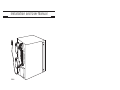
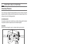
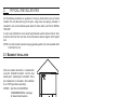
Broan AE60 is a versatile air exchanger designed for residential use. It operates in three modes: air recirculation, circulation with air exchange, and air exchange. In the air exchange mode, it replaces stale indoor air with fresh outdoor air, helping to improve indoor air quality and reduce humidity levels. It features a mechanical filter to trap dust particles and a variety of installation options, including basement, attic, and retrofit applications.
Broan AE60 is a versatile air exchanger designed for residential use. It operates in three modes: air recirculation, circulation with air exchange, and air exchange. In the air exchange mode, it replaces stale indoor air with fresh outdoor air, helping to improve indoor air quality and reduce humidity levels. It features a mechanical filter to trap dust particles and a variety of installation options, including basement, attic, and retrofit applications.


-
 1
1
-
 2
2
-
 3
3
-
 4
4
-
 5
5
-
 6
6
-
 7
7
-
 8
8
-
 9
9
-
 10
10
-
 11
11
-
 12
12
-
 13
13
-
 14
14
-
 15
15
-
 16
16
-
 17
17
-
 18
18
-
 19
19
-
 20
20
-
 21
21
-
 22
22
-
 23
23
-
 24
24


Broan AE60 is a versatile air exchanger designed for residential use. It operates in three modes: air recirculation, circulation with air exchange, and air exchange. In the air exchange mode, it replaces stale indoor air with fresh outdoor air, helping to improve indoor air quality and reduce humidity levels. It features a mechanical filter to trap dust particles and a variety of installation options, including basement, attic, and retrofit applications.
Ask a question and I''ll find the answer in the document
Finding information in a document is now easier with AI
Related papers
-
Broan HRVH100SE Installation guide
-
-
-
-
-
-
-
-
-
Other documents
-
NuTone Guardian AE60 Installation and User Manual
-
Decor Grates (Import) PL412-OC User manual
-
Venmar Transition Tandem Installation guide
-
 Venmar Metal tandem hood Installation guide
-
Master Flow INSLV6 Specification
-
 Venmar K7 HRV User guide
-
 Venmar PRO215 User guide
-
 SPEEDI-GRILLE SG-2414 FG User manual
-
SPEEDI-GRILLE TB-3HC 06 User manual
-


