Page is loading ...

W4, W5, W7, W9 Control Heads
User's Guide
ASTRO
®
XTL
TM
5000
Digital Mobile Radio


ASTRO
®
XTL™ 5000 Digital
Mobile Radio with W4
Control Head
Quick Reference Card
Product Safety and RF Exposure Compliance
ATTENTION!
This radio is restricted to occupational use only to satisfy
FCC RF energy exposure requirements. Before using this
product, read the RF energy awareness information and
operating instructions in the Product Safety and RF
Exposure booklet enclosed with your radio (Motorola
Publication part number 6881095C99) to ensure
compliance with RF energy exposure limits.
BASIC OPERATION
Turning the Radio On and Off
Setting the Volume and Squelch
Changing Modes
Transmitting
Transmitting (Conventional Modes)
Activating Scan
Programming a Scan List
Selecting Scan Mode Priority
Before using this product, read the operating instructions
for safe usage contained in the Product Safety and RF
Exposure booklet enclosed with your radio.
!
C
a u t i o
n
PHONE
PAGE
or
SECURE
or
EMERGENCY
Page
Emer
CALL DIRECT
XMIT
BUSY
Mode
Volume
Pwr
Phon
Call SelScan
Mic
Home
Dim
H/L
Dir Mon
SCAN SELECT MONITOR
MODE
KNOB
POWER ON/OFF/
VOLUME KNOB
H
OME
H
ORN/
LI
GHTS
PRIORITY/
NON-PRIORITY
INDICATORS
DIRECT
INDICATOR
Rotate the Vol (Volume) knob clockwise.
1 Turn the Vol knob clockwise to increase volume or
counterclockwise to decrease volume as desired.
2 On conventional modes with Private-Line or Digital
Private-Line, press Mon or remove the microphone
from the hang-up clip to defeat the coded squelch.
3 Press Mon again, or replace the microphone on the
hang-up clip to return to coded-squelch operation.
4 To adjust squelch level, hold Mon until a tone sounds.
5 Turn Mode knob to select squelch level.
6 Press Home.
Turn the Mode knob to select the desired mode
OR
Press Home to access the preprogrammed Home
mode.
1 Press and hold the microphone PTT button.
2 When the transmit light comes on solid and no alert
tones sound (or a talk-permit tone or ID sidetone
sounds), speak into the microphone in a normal voice.
3 State your FCC call sign at the beginning of each
transmission.
1 Press Dir (Direct). The Dir indicator lights.
2 Press Dir again to return to repeater operation.
1 Press Scan to start a scan. If no activity exists, the
display shows your selected mode. When a scanned
channel or talkgroup becomes active, the display
shows the active mode name. The PRI and NPRI
indicators show priority.
2 Press Scan again to stop scanning.
1 Hold Scan until a tone sounds and the scan indicator
blinks.
2 Turn the Mode knob to select the mode you want to
program.
3 Press the Sel button as indicated in the table below to
add or remove the displayed mode from the scan list.
4 Repeat the previous steps to continue editing the list.
5 Press Home or Scan to exit.
Press Sel Mode Indicator
One time Non-Priority NPRI lit
Two times Second Priority PRI lit
Three times First Priority PRI blinks
Four times Delete from List No indicator
1 Press the Sel button as indicated in the table above
to designate up to two modes as priorities.
2 Press Home or Scan to end scan list selection.

Sending an Emergency Alarm or Call
Sending a Status Transmission
Sending a Direct-Entry Keyboard Status
Transmission
Sending a Direct-Entry Enhanced Private
Conversation Call
Initiating a Call Alert Page
Answering a Call Alert Page
Press the emergency actuator (Emer button,
footswitch, hidden pushbutton) to begin an
emergency transmission.
For conventional modes, a silent or non-silent
emergency alarm data transmission is sent.
For trunked modes, emergency call (priority access
to a voice channel), silent or non-silent emergency
alarm, or emergency alarm and call is entered.
Depending on your radio's programming, one of the
emergency sequences described in the table below
occur.
Alarm Type Indications/Actions
Non-Silent A tone sounds and the display
alternates between EMERGNCY and the
zone/channel. When acknowledged,
four more tones sound and the display
shows ACK RCVD, then the radio
returns to normal operation.
Silent The audio is muted and no display
changes take place during the alarm.
Press the PTT button, or press and
hold the emergency button to stop the
emergency condition and unmute the
radio.
Call (Trunked
Modes only)
A tone sounds and the display
alternates between EMERGNCY and the
zone/channel.
Press the PTT button and talk.
After completing the call, press and
hold the emergency actuator until a
tone sounds to return to normal
operation.
Alarm and Call After ACK RCVD (see Non-Silent Alarm
above) is displayed, the radio has
priority voice-channel access.
Press the PTT button and talk.
After completing the call, press and
hold the emergency actuator until a
tone sounds to return to normal
operation.
1 Press Sts. The display shows the last acknowledged
status or first status name.
2 Rotate Mode to select other statuses.
3 Press Sel to send the transmission. The display
flashes the selected status/message name until the
dispatcher acknowledges, at which time alert tones
sound and the display shows ACK RCVD. The radio
then returns to normal operation.
Press the appropriate Sts # button you wish to send.
The associated indicator blinks until an
acknowledgment is received, then it lights steadily.
1 Press Sel or the PTT button. A single tone sounds
and the display changes to PLS WAIT, followed by
telephone-type ringing if the receiving unit is in
service.
Alarm Type Indications/Actions
2 If the receiving unit answers, press the PTT button to
identify yourself and proceed with your call.
OR
If the called unit does not respond, press Sel or the
PTT button again to leave a Call Alert page message
and your ID.
A single tone followed by four tones sounds if the
called unit acknowledges the page.
1 Press the Page button.
2 Follow the instructions for initiating a Private
Conversation to select a unit ID.
3 Press Sel or the PTT button to send a Call Alert page
to the displayed ID,
OR
To send a Call Alert page following an Enhanced
Private Conversation attempt, follow the instructions
for sending a direct-entry Enhanced Private
Conversation call.
Four tones sound and PAGE RCV flashes on the
display. The tone and display repeat every five
seconds.
1 Press the PTT button,
OR
Initiate an Enhanced Private Conversation call to the
caller.

Selecting a Zone/Mode (Optional)
Selecting a Home Zone/Home Mode
Selecting Secure Mode
Selecting an Encryption Key
Selecting a Key Index
Erasing an Encryption Key
DISPLAY AND LIGHT INDICATORS
1 Press the Zone Up button or Zone Down
button to scroll to the desired zone.
2 Turn the Mode knob to select the mode.
Press the Home button.
Press and release the D button. The D indicator
lights up.
1 Press and hold the D button until a tone sounds.
2 Turn the Mode knob to scroll to KEY SEL.
3 Press Sel to enter the Key Selection Menu.
4 Turn the Mode knob to select desired key.
5 Press Sel to select key.
6 Press Home or the PTT button to quit.
1 Press and hold the D button until a tone sounds.
2 Turn the Mode knob to scroll to INDX SEL.
3 Press Sel to enter the Index Selection Menu.
4 Turn the Mode knob to select desired index.
5 Press Sel to select index.
6 Press Home or the PTT button to quit.
1 Press and hold the D button until a tone sounds.
2 Turn the Mode knob to scroll to ERASE KY.
3 Press Sel to enter the Key Erase Menu.
4 Turn the Mode knob to select desired index.
5 Press Sel to select index.
6 Press Home or the PTT button to quit.
Display/Light Meaning
BUSY light on Displayed conventional mode has
activity on it, or selected trunked
system is currently busy. Wait for
callback.
XMIT light on Indicates you are transmitting.
Dir indicator lit Radio is in direct (mobile-to-
mobile) operation.
PRI, NPRI
indicators lit
Display shows a mode in the scan
list with the indicated priority level.
P displayed Telephone dialing pause. Press
Sel to continue the dialing.
NO ACK displayed Unit being called with the
Enhanced Private Conversation or
Call Alert Page feature is not in
service, or emergency alarm or
status/message transmission is
not acknowledged by dispatcher.
NO ANSWR
displayed
Unit being called with Enhanced
Private Conversation or Call Alert
Page does not respond, but is
operational.
EMERGNCY
displayed
Radio is in emergency alarm or call
state.
NO EMERG
displayed
A mode incapable of emergency
transmission has been selected.
OUT RNG displayed Radio is out of range of the
trunking system.

Examples: Not exiting phone mode after a call (radio
cannot receive fleet or subfleet calls), transmitting in
receive-only conventional mode, trying to select a dynamic
mode when no dynamic ID assignment has been made.
ALERT TONES
Type of Tone Name Explanation
1 Low-Pitched
Tone
Invalid Key
Alert
Feature button
pressed is not valid
in selected mode, or
a Call Alert or
emergency alarm
was not
acknowledged.
1 High-Pitched
Tone
Central
Acknowledge
or Valid Key
Central controller
has received request
for Call Alert or
emergency alarm
transmission.
You pressed a valid
key.
4 High-Pitched
Tones
Dispatcher or
Mobile Unit
Acknowledge
Dispatcher is
acknowledging your
emergency
transmission. Mobile
unit has received
your Call Alert.
5 High-Pitched
Tones
The above two
acknowledge tones,
heard in tandem.
2 High-Pitched
Tones
Private
Conversation
You have an
incoming call. Press
Call, then the PTT
button, then talk.
4 High-Pitched
Tones every 6
seconds
Call Alert Page Call Alert page has
been received.
Phone-Type
Busy Tone
(when pressing
the PTT button)
System Busy All system radio
channels in use.
Release the PTT
button, and wait for
callback.
3 Short High-
Tones (after
requesting a
busy channel)
upon pressing
the PTT button)
Automatic Call
Back or Talk
Permit
Channel is available
for previously
requested
transmission.
System is accepting
your transmission.
Low-Pitched
Tone (upon
pressing the
PTT button
during Transmit)
(Operation
Error)
Talk Prohibit/
Out-of-Range
or Time-Out
Timer or Illegal
Mode
Out of trunked radio
system range or
system is out of
service.
Present transmission
will soon be disabled.
You have entered a
mode where normal
system traffic will be
missed, or you
attempted something
that is not allowed.
(See examples
below.)
High-Pitched
Tone every 10
seconds in
unmuted receive
condition
Failsoft System central
controller failure. The
radio reverts from
trunked operation to
operation similar to a
conventional
repeater.
Others may share
the channel.
ALERT TONES (Continued)
Type of Tone Name Explanation

ASTRO
®
XTL™ 5000 Digital
Mobile Radios with W5
Control Head
Quick Reference Card
Product Safety and RF Exposure Compliance
ATTENTION!
This radio is restricted to occupational use only to satisfy
FCC RF energy exposure requirements. Before using this
product, read the RF energy awareness information and
operating instructions in the Product Safety and RF
Exposure booklet enclosed with your radio (Motorola
Publication part number 6881095C99) to ensure
compliance with RF energy exposure limits.
BASIC OPERATION
Turning the Radio On and Off
Setting the Volume and Squelch
Changing Modes
Transmittingt
Transmitting (Conventional Modes)
Activating Scan
Programming a Scan List
Selecting Scan Mode Priority
Before using this product, read the operating instructions
for safe usage contained in the Product Safety and RF
Exposure booklet enclosed with your radio.
!
C
a u t i o
n
Mode
Vol
Mic
Phon
Call Sel
H/L Mon Dir
PWR
Scan
XMIT
BUSY
DIM
HOME
MODE
POWER
ON/OFF
PAGE
or
SECURE
or
EMERGENCY
Page
Emer
PHONE
SCAN
CALL
SELECT
VOLUME
PRIORITY/
NON-PRIORITY
INDICATORS
DIRECT
INDICATOR
HORN/
LIGHTS
MONITOR
DIRECT
HOME
Press the PWR button once.
1 Hold the Vol rocker switch down to increase or
decrease volume as desired, then release.
The display shows volume levels from 0 to 15.
2 On conventional modes with Private-Line or Digital
Private-Line, press Mon or remove the microphone
from the hang-up clip to defeat the coded squelch.
3 Press Mon again, or replace the microphone on the
hang-up clip to return to coded-squelch operation.
4 To adjust squelch level, hold Mon until a tone sounds.
5 Press the Mode rocker switch to select squelch level.
6 Press HOME.
Press the Mode rocker switch to select the desired
mode
OR
Press HOME to access the preprogrammed Home
mode.
1 Press and hold the microphone PTT button.
2 When the transmit light comes on solid and no alert
tones sound (or a talk-permit tone or ID sidetone
sounds), speak into the microphone in a normal voice.
3 State your FCC call sign at the beginning of each
transmission.
1 Press Dir (Direct). The Dir indicator lights.
2 Press Dir again to return to repeater operation.
1 Press Scan to start a scan. If no activity exists, the
display shows your selected mode. When a scanned
channel or talkgroup becomes active, the display
shows the active mode name. The PRI and NPRI
indicators show priority.
2 Press Scan again to stop scanning.
1 Hold Scan until a tone sounds and the scan indicator
blinks.
2 Press the Mode rocker switch to select the mode you
want to program.
3 Press the Sel button as indicated in the table below to
add or remove the displayed mode from the scan list.
4 Repeat the previous steps to continue editing the list.
5 Press HOME or Scan to exit.
Press Sel Mode Indicator
One time Non-Priority NPRI lit
Two times Second Priority PRI lit
Three times First Priority PRI blinks
Four times Delete from List No indicator
1 Press the Sel button as indicated in the table above
to designate up to two modes as priorities.
2 Press HOME or Scan to end scan list selection.

Sending an Emergency Alarm or Call
Sending a Status Transmission
Sending a Direct-Entry Keyboard Status
Transmission
Sending a Direct-Entry Enhanced Private
Conversation Call
Initiating a Call Alert Page
Answering a Call Alert Page
Press the emergency actuator (Emer button,
footswitch, hidden pushbutton) to begin an emergency
transmission.
For conventional modes, a silent or non-silent
emergency alarm data transmission is sent.
For trunked modes, emergency call (priority access to
a voice channel), silent or non-silent emergency
alarm, or emergency alarm and call is entered.
Depending on your radio's programming, one of the
emergency sequences described in the table below
occur.
Alarm Type Indications/Actions
Non-Silent A tone sounds and the display flashes
EMERGNCY. When acknowledged, four
more tones sound and the display
shows ACK RCVD, then the radio
returns to normal operation.
Silent The audio is muted and no display
changes take place during the alarm.
Press the PTT button, or press and
hold the emergency button to stop the
emergency condition and unmute the
radio.
Call (Trunked
Modes only)
A tone sounds and the display flashes
EMERGNCY.
Press the PTT button and talk.
After completing the call, press and
hold the emergency actuator until a
tone sounds to return to normal
operation.
Alarm and Call After the display shows ACK RCVD (see
Non-Silent Alarm above), the radio has
priority voice-channel access.
Press the PTT button and talk.
After completing the call, press and
hold the emergency actuator until a
tone sounds to return to normal
operation.
1 Press Sts. The display shows the last acknowledged
status or the first status name.
2 Press the Mode rocker switch to select other
statuses.
3 Press Sel to send the transmission. The display
flashes the selected status name until the dispatcher
acknowledges, at which time alert tones sound and
the display shows ACK RCVD. The radio then returns
to normal operation.
Press the appropriate Sts # button that you wish to
send. The associated indicator blinks until an
acknowledgment is received, then it lights steadily.
1 Press Sel or the PTT button. A single tone sounds
and the display changes to PLS WAIT, followed by
telephone-type ringing if the receiving unit is in
service.
Alarm Type Indications/Actions
2 If the receiving unit answers, press the PTT button to
identify yourself and proceed with your call.
OR
If the called unit does not respond, press Sel or the
PTT button again to leave a Call Alert page message
and your ID.
A single tone followed by four tones sounds if the
called unit acknowledges the page.
1 Press the Page button.
2 Follow the instructions for initiating a Private
Conversation to select a unit ID.
3 Press Sel or the PTT button to send a Call Alert page
to the displayed ID,
OR
To send a Call Alert page following an Enhanced
Private Conversation attempt, follow the instructions
for sending a direct-entry Enhanced Private
Conversation call.
Four tones sound and PAGE RCV flashes on the
display. The tone and display repeat every five
seconds.
1 Press the PTT button,
OR
Initiate an Enhanced Private Conversation call to the
caller.

Selecting a Zone/Mode (Optional)
Selecting a Home Zone/Home Mode
Selecting Secure Mode
Selecting an Encryption Key
Selecting a Key Index
Erasing an Encryption Key
DISPLAY AND LIGHT INDICATORS
1 Press the Zone Up button or Zone Down
button to scroll to the desired zone.
2 Press the Mode rocker switch to select the mode.
Press the HOME button.
Press and release the D button. The D indicator
lights up.
1 Press and hold the D button until a tone sounds.
2 Press the Mode rocker switch to scroll to KEY SEL.
3 Press Sel to enter the Key Selection Menu.
4 Press the Mode rocker switch to select the desired
key.
5 Press Sel to select the key.
6 Press HOME or the PTT button to quit.
1 Press and hold the D button until a tone sounds.
2 Press the Mode rocker switch to scroll to INDX SEL.
3 Press Sel to enter the Index Selection Menu.
4 Press the Mode rocker switch to select the desired
index.
5 Press Sel to select the index.
6 Press HOME or the PTT button to quit.
1 Press and hold the D button until a tone sounds.
2 Press the Mode rocker switch to scroll to ERASE KY.
3 Press Sel to enter the Key Erase Menu.
4 Press the Mode rocker switch to select the desired
index.
5 Press Sel to select the index.
6 Press HOME or the PTT button to quit.
Display/Light Meaning
BUSY light on The conventional mode in the
display has activity on it, or
selected trunked system is
currently busy. Wait for callback.
XMIT light on Indicates you are transmitting.
Dir indicator lit Radio is in direct (mobile-to-
mobile) operation.
PRI, NPRI
indicators lit
The display shows the mode in the
scan list with the indicated priority
level.
P displayed Telephone dialing pause. Press
Sel to continue the dialing.
NO ACK displayed Unit being called with the
Enhanced Private Conversation or
Call Alert Page feature is not in
service, or emergency alarm or
status/message transmission is
not acknowledged by dispatcher.
NO ANSWR
displayed
Unit being called with Enhanced
Private Conversation or Call Alert
Page does not respond, but is
operational.
EMERGNCY
displayed
Radio is in emergency alarm or
call state.
NO EMERG
displayed
A mode incapable of emergency
transmission has been selected.
OUT RNG displayed Radio is out of range of the
trunking system.

Examples: Not exiting phone mode after a call (radio
cannot receive fleet or subfleet calls), transmitting in
receive-only conventional mode, trying to select a dynamic
mode when no dynamic ID assignment has been made.
ALERT TONES
Type of Tone Name Explanation
1 Low-Pitched
Tone
Invalid Key
Alert
Feature button
pressed is not valid
in selected mode, or
a Call Alert or
emergency alarm
was not
acknowledged.
1 High-Pitched
Tone
Central
Acknowledge
or Valid Key
Central controller
has received request
for Call Alert or
emergency alarm
transmission.
You pressed a valid
key.
4 High-Pitched
Tones
Dispatcher or
Mobile Unit
Acknowledge
Dispatcher is
acknowledging your
emergency
transmission. Mobile
unit has received
your Call Alert.
5 High-Pitched
Tones
The above two
acknowledge tones,
heard in tandem.
2 High-Pitched
Tones
Private
Conversation
You have an
incoming call. Press
Call, then the PTT
button, then talk.
4 High-Pitched
Tones every 6
seconds
Call Alert Page Call Alert page has
been received.
Phone-Type
Busy Tone
(when pressing
the PTT button)
System Busy All system radio
channels in use.
Release the PTT
button, and wait for
callback.
3 Short High-
Tones (after
requesting a
busy channel)
upon pressing
the PTT button)
Automatic Call
Back or Talk
Permit
Channel is available
for previously
requested
transmission.
System is accepting
your transmission.
Low-Pitched
Tone (upon
pressing the
PTT button
during Transmit)
(Operation
Error)
Talk Prohibit/
Out-of-Range
or Time-Out
Timer or Illegal
Mode
Out of trunked radio
system range or
system is out of
service.
Present transmission
will soon be disabled.
You have entered a
mode where normal
system traffic will be
missed, or you
attempted something
that is not allowed.
(See examples
below.)
High-Pitched
Tone every 10
seconds in
unmuted receive
condition
Failsoft System central
controller failure. The
radio reverts from
trunked operation to
operation similar to a
conventional
repeater.
Others may share
the channel.
ALERT TONES (Continued)
Type of Tone Name Explanation


ii
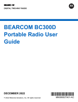
W4 and W5 Control Heads Foldout Page
W4 Control Head
W5 Control Head
PHONE
PAGE
or
SECURE
or
EMERGENCY
Page
Emer
CALL DIRECT
XMIT
BUSY
Mode
Volume
Pwr
Phon
Call SelScan
Mic
Home
Dim
H/L
Dir Mon
SCAN SELECT MONITOR
MODE
KNOB
POWER ON/OFF/
VOLUME KNOB
HOME
HORN/
L
IGHTS
MAEPF-23211-A
PRIORITY/
NON-PRIORITY
INDICATORS
DIRECT
INDICATOR
Mode
Vol
Mic
Phon
Call Sel
H/L Mon Dir
PWR
Scan
XMIT
BUSY
DIM
HOME
MAEPF-23212-A
MODE
POWER
ON/OFF
PAGE
or
SECURE
or
EMERGENCY
Page
Emer
PHONE
SCAN
CALL
SELECT
VOLUME
PRIORITY/
NON-PRIORITY
INDICATORS
DIRECT
INDICATOR
HORN/
LIGHTS
MONITOR
DIRECT
HOME

ASTRO XTL 5000 Digital Mobile Radio with W4, W5, W7, and W9 iii
ASTRO
®
XTL™ 5000
Digital Mobile Radio
with
W4, W5, W7, and W9
Control Heads
User’s Guide
6881096C68-D

iv
This declaration is applicable to your radio only if your radio is labeled
with the FCC logo shown below.
DECLARATION OF CONFORMITY
Per FCC CFR 47 Part 2 Section 2.1077(a)
Responsible Party
Name: Motorola, Inc.
Address: 8000 West Sunrise Boulevard
Plantation, FL 33322 USA
Phone Number: 1-888-567-7347
Hereby declares that the product:
Model Name: XTL 5000
conforms to the following regulations:
FCC Part 15, subpart B, section 15.107(a), 15.107(d) and section 15.109(a)
Class B Digital Device
As a personal computer peripheral, this device complies with Part 15 of the FCC
Rules. Operation is subject to the following two conditions:
1. this device may not cause harmful interference, and
2. this device must accept any interference received, including interference that
may cause undesired operation.
Note: This equipment has been tested and found to comply with the limits for a
Class B digital device, pursuant to part 15 of the FCC Rules. These limits are
designed to provide reasonable protection against harmful interference in a
residential installation. This equipment generates, uses and can radiate radio
frequency energy and, if not installed and used in accordance with the
instructions, may cause harmful interference to radio communications.
However, there is no guarantee that interference will not occur in a particular
installation.
If this equipment does cause harmful interference to radio or television reception,
which can be determined by turning the equipment off and on, the user is
encouraged to try to correct the interference by one or more of the following
measures:
• Reorient or relocate the receiving antenna.
• Increase the separation between the equipment and receiver.
• Connect the equipment into an outlet on a circuit different from that to which
the receiver is connected.
• Consult the dealer or an experienced radio/TV technician for help.

ASTRO XTL 5000 Digital Mobile Radio with W4, W5, W7, and W9 v
Product Safety and RF Exposure Compliance
ATTENTION!
This radio is restricted to occupational use only to satisfy FCC RF energy
exposure requirements. Before using this product, read the RF energy
awareness information and operating instructions in the Product Safety and RF
Exposure booklet enclosed with your radio (Motorola Publication part number
6881095C99) to ensure compliance with RF energy exposure limits.
Computer Software Copyrights
The Motorola products described in this manual may include copyrighted Motorola
computer programs stored in semiconductor memories or other media. Laws in the
United States and other countries preserve for Motorola certain exclusive rights for
copyrighted computer programs, including, but not limited to, the exclusive right to copy
or reproduce in any form the copyrighted computer program. Accordingly, any
copyrighted Motorola computer programs contained in the Motorola products described
in this manual may not be copied, reproduced, modified, reverse-engineered, or
distributed in any manner without the express written permission of Motorola.
Furthermore, the purchase of Motorola products shall not be deemed to grant either
directly or by implication, estoppel, or otherwise, any license under the copyrights,
patents or patent applications of Motorola, except for the normal non-exclusive license
to use that arises by operation of law in the sale of a product.
Documentation Copyrights
No duplication or distribution of this document or any portion thereof shall take place
without the express written permission of Motorola. No part of this manual may be
reproduced, distributed, or transmitted in any form or by any means, electronic or
mechanical, for any purpose without the express written permission of Motorola.
Disclaimer
The information in this document is carefully examined, and is believed to be entirely
reliable. However, no responsibility is assumed for inaccuracies. Furthermore, Motorola
reserves the right to make changes to any products herein to improve readability,
function, or design. Motorola does not assume any liability arising out of the
applications or use of any product or circuit described herein; nor does it cover any
license under its patent rights, nor the rights of others.
Patent Disclosure
This product is covered by one or more of the following United States patents:
4,512,035 4,551,856 4,653,117 4,816,774 4,829,594 4,837,853 4,864,2524,885,550
4,914,321 4,918,403 4,959,617 4,975,650 4,994,768 5,006,7305,021,754 5,079,526
MOTOROLA, the Stylized M Logo, ASTRO, SmartZone, and FLASHport are registered
in the U.S. Patent & Trademark Office. All other product or service names are the
property of their respective owners. P25 radios contain technology patented by Digital
Voice Systems, Inc.
© Motorola, Inc. 2004. All Rights Reserved. Printed in the U.S.A. 8/04.
Before using this product, read the operating instructions for safe
usage contained in the Product Safety and RF Exposure booklet
enclosed with your radio.
!
C
a u t i o
n

vi
Notations Used in This Manual
Throughout the text in this publication, you will notice the use of WARNINGS,
CAUTIONS, and Notes. These notations are used to emphasize that safety
hazards exist, and care that must be taken or observed.
The following special notations identify certain items:
WARNING: An operational procedure, practice, or other
condition, which might result in injury or death if not carefully
observed.
CAUTION: An operational procedure, practice, or other
condition, which might result in damage to the equipment if not
carefully observed.
Note: Note: An operational procedure, practice, or other condition,
which is essential to emphasize.
Example Description
Light button or
>
Buttons and keys are shown in bold print or as a key
symbol.
PHONE
Menu items (softkeys) are similar to the way they
appear on the radio’s display.
WARNING
!
CAUTION
!

ASTRO XTL 5000 Digital Mobile Radio with W4, W5, W7, and W9 vii
Contents
W4 and W5 Control Heads Foldout Page . . . . . . . . . . ii
Declaration of Conformity ................................................................. iv
Computer Software Copyrights ......................................................... v
Documentation Copyrights ................................................................ v
Disclaimer ......................................................................................... v
Patent Disclosure .............................................................................. v
Notations Used in This Manual ........................................................ vi
Introduction . . . . . . . . . . . . . . . . . . . . . . . . . . . . . . . . . . 1
Using Your Radio: The Basics .......................................................... 1
Getting Started .................................................................................. 2
Identifying Your Radio ....................................................................... 4
W4 Control Head ........................................................................ 4
W5 Control Head ........................................................................ 4
W7 Control Head ........................................................................ 4
W9 Control Head ........................................................................ 4
Operating Your Control Head ............................................................ 5
Turning On the Radio ........................................................................ 5
Setting the Volume ..................................................................... 6
Adjusting the Display Brightness ................................................ 6
Trunked Modes or Conventional Channels ................................ 7
Field Programming ..................................................................... 7
Display Status ................................................................................... 8
Feature Control ................................................................................. 8
Alert Tones ........................................................................................ 8
Basic Operating Procedures . . . . . . . . . . . . . . . . . . . 11
Basic Functions ............................................................................... 11
Selecting the Zone or Mode ............................................................ 12
Selecting or Changing the Zone ............................................... 12
Selecting or Changing a Mode in the Current Zone ................. 13
Selecting or Changing to a Mode Not in the Current Zone ....... 13
Selecting the Home Mode ............................................................... 14
Transmitting (Conventional Modes Only) ........................................ 15
Transmitting (Trunked Modes Only) ................................................ 15
Selecting the Transmit Power Level ................................................ 16
Monitoring Conventional Mode Activity ........................................... 17
Adjusting the Squelch Level ............................................................ 18

viii
General Radio Features . . . . . . . . . . . . . . . . . . . . . . . 19
Often-Used Features .......................................................................19
Emergency Call and Alarm ..............................................................20
Emergency Call .........................................................................20
Initiating an Emergency Alarm ..................................................21
Initiating an Emergency Call .....................................................22
Initiating an Emergency Call and Alarm ....................................23
Initiating a Silent Emergency Alarm ..........................................24
Special Considerations for Emergencies ..................................25
Scan Operation ................................................................................26
Turning On Scan .......................................................................27
Turning Scan On While Disregarding the Squelch Code
(Conventional Modes Only) ...................................................28
Viewing a Scan List ...................................................................29
Transmitting While Scan Is On .................................................30
Temporarily Deleting a Nuisance Mode with Scan On
(W7 and W9 Control Heads Only) .........................................31
Restoring a Nuisance Mode
(W7 and W9 Control Heads Only) .........................................32
Changing Mode Priorities While Scan Is On
(W7 and W9 Control Heads Only) .........................................33
Restoring Mode Priorities in a Scan List
(W7 and W9 Control Heads Only) .........................................33
Programming a Scan List ..........................................................34
Hang Up Box (HUB) ..................................................................36
Optional External Alarms (Horn and Lights) ....................................36
Activating the External Alarm(s) ................................................36
Changing the Selected Alarms .................................................38
Receiving a Call While Alarms Are Turned On .........................39
Time-Out Timer ................................................................................40
Push-To-Talk Identification (PTT-ID) ................................................40
Telephone Interconnect List (Conventional and Trunking) ..............41
Answering a Phone Call ............................................................42
Initiating a Telephone Call from the List ....................................42
Unlimited Telephone Interconnect
(W7 and W9 Control Heads Only) ..................................................44
Calling a Phone Number Not in the List ....................................44
Storing a Number in the List .....................................................46
Editing a Name in the List
(W7 and W9 Control Heads Only) .........................................47

ASTRO XTL 5000 Digital Mobile Radio with W4, W5, W7, and W9 ix
Call Alert Page (Conventional and Trunking— Digital Modes Only) 50
Sending a Call Alert Page ........................................................ 51
Answering a Call Alert Page ..................................................... 53
Storing a Unit ID Number in the List
(W7 and W9 Control Heads Only) ......................................... 54
Editing a Name in the List
(W7 and W9 Control Heads Only) ......................................... 55
Conventional Radio Features. . . . . . . . . . . . . . . . . . . 57
Features Used in Conventional Operation ...................................... 57
Status Calls (Digital Modes Only) .................................................... 58
Sending a Status Call (W7 and W9 Control Heads Only) ........ 58
Sending a Direct-Entry Keyboard (DEK) Status
(Digital Modes Only) .............................................................. 60
Smart PTT ....................................................................................... 61
Conventional Talkgroup Calls ......................................................... 62
Digital Modes Only ................................................................... 62
Selecting a Conventional Talkgroup ......................................... 62
Conventional Talkaround ................................................................ 64
Talk Direct (Mobile-To-Mobile) ................................................. 64
Selective Calls (Digital Modes Only) ............................................... 65
Answering a Selective Call ....................................................... 66
Initiating a Selective Call .......................................................... 67
Viewing Your Unit ID Number ................................................... 69
Storing a Unit ID Number in the List
(W7 and W9 Control Heads Only) ......................................... 70
Editing a Name in the List
(W7 and W9 Control Heads Only) ......................................... 71
Trunking Operation . . . . . . . . . . . . . . . . . . . . . . . . . . . 73
Features Used on Trunking Systems .............................................. 73
Enhanced Private Conversation (Digital Modes Only) .................... 74
Answering an Enhanced Private Conversation Call ................. 75
Initiating an Enhanced Private Conversation Call .................... 76
Storing a Unit ID Number in the
Private Conversation List
(W7 and W9 Control Heads Only) ......................................... 78
Editing a Name in the
Private Conversation List
(W7 and W9 Control Heads Only) ......................................... 79

x
Failsoft .............................................................................................81
Dynamic Regrouping (Digital Modes Only) .....................................82
Receiving a Dynamic Regrouping ID Assignment
(W7 and W9 Control Heads Only) .........................................82
Selecting Enable and Disable (Digital Modes Only) ..................83
Requesting a Dynamic Regrouping
(W7 and W9 Control Heads Only) (Digital Modes Only) ........83
SmartZone (W7 and W9 Control Heads Only) ................................85
Site-Button Operation ...............................................................86
Locking onto a Site ...................................................................87
Site Trunking .............................................................................88
Out-of-Range Indication ..................................................................89
Trunked Announcement ..................................................................90
Initiating an Announcement ......................................................91
Secure Operation . . . . . . . . . . . . . . . . . . . . . . . . . . . . 93
Features Available on Secure XTL 5000 .........................................93
Receiving a Private Message ..........................................................94
Transmitting a Private Message ......................................................94
System Considerations ....................................................................95
Loss Indication .................................................................................96
Selecting an Encryption Key (Conventional Only) ...........................97
Selecting an Encryption Index (Conventional Only) ........................99
Troubleshooting . . . . . . . . . . . . . . . . . . . . . . . . . . . . 100
Accessories. . . . . . . . . . . . . . . . . . . . . . . . . . . . . . . . 101
Antennas .......................................................................................101
Bull Horns for Siren and Public Address .......................................102
Cables ...........................................................................................102
Microphones ..................................................................................103
Miscellaneous ................................................................................103
Remote Mounting Kits ...................................................................104
Speakers ........................................................................................104
Trunnion Kits ..................................................................................104
Appendix: Maritime Radio Use in the
VHF Frequency Range . . . . . . . . . . . . . . . . . . . . . . . 105
Special Channel Assignments .......................................................105
Emergency Channel ...............................................................105
/