PC CHIPS M916 (V1.3a) Specification
- Category
- Motherboards
- Type
- Specification

This publication, photographs, illustrations and software are under
the protection of international copyright laws and all rights
reserved. It does not allow any reproduction of this manual,
content and any materials contained herein without the written
consent of the authentic manufacturer.
The information in this manual is subject to change without notice.
The manufacturer does neither represent nor warrant the contents
hereof; and specifically disclaims any implied warranties of
merchantability or fitness for any particular purpose. Furthermore,
the manufacturer reserves the right to revise and change this
publication from time to time, without the obligation of notifying
any person of such revision or changes.
Trademarks
IBM, VGA, and PS/2 are registered trademarks of International
Business Machines.
Intel, Pentium/II/III, Pentium 4, Celeron and MMX are registered
trademarks of Intel Corporation.
Microsoft, MS-DOS and Windows 98/ME/NT/2000/XP are
registered trademarks of Microsoft Corporation.
PC-cillin is a trademark of Trend Micro Inc.
AMI is a trademark of American Megatrends Inc.
It has been acknowledged that other brands or product names in
this manual are trademarks or the properties of their respective
owners.
Copyright © 2003
All Rights Reserved
M916 Series, V1.3A
868ProHT1683/October 2003

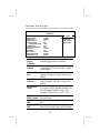
Table of Contents
Trademark.....................................................................................I
Static Electricity Precautions.................................................III
Pre-Installation Inspection.....................................................III
Features & Checklist Translations.............................................. V
Chapter 1: Introduction.................................................................1
Key Features.............................................................................2
Package Contents......................................................................5
Chapter 2: Mainboard Installation................................................6
Mainboard Components ...........................................................7
I/O Ports....................................................................................7
Installing the Processor.............................................................8
Installing Memory Modules .....................................................9
Jumper Settings.......................................................................10
Install The Mainboard ............................................................11
Connecting Optional Devices.................................................12
Install Other Devices ..............................................................14
Expansion Slots .....................................................................16
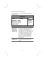
Chapter 3: BIOS Setup Utility.....................................................17
Introduction ............................................................................17
Running the Setup Utility............…………………………...18
Standard CMOS Setup Page...................................................19
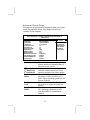
Advanced Setup Page.............................................................20
Features Setup Page................................................................22
Power Management Setup Page .............................................23
PCI/Plug and Play Setup Page................................................25
BIOS Security Features Setup Page .......................................26
CPU PnP Setup Page..............................................................27
Hardware Monitor Page..........................................................28
Load Optimal Defaults ...........................................................28
Save Changes and Exit. .........................................................28
Discard Changes and Exit. .....................................................29
Chapter 4: Software & Applications ..........................................30
Introduction ............................................................................30
Installing Support Software....................................................31
Bundled Software Installation................................................33
Hyper Threading CPU............................................................34
II

Static Electricity Precautions
Static electricity could damage components on this mainboard.
Take the following precautions while unpacking this mainboard
and installing it in a system.
1. Don’t take this mainboard and components out of their original
static-proof package until you are ready to install them.
2. While installing, please wear a grounded wrist strap if possible.
If you don’t have a wrist strap, discharge static electricity by
touching the bare metal of the system chassis.
3. Carefully hold this mainboard by its edges. Do not touch those
components unless it is absolutely necessary. Put this
mainboard on the top of a static-protection package with
component side facing up while installing.
Pre-Installation Inspection
1. Inspect this mainboard whether there are any damages to
components and connectors on the board.
2. If you suspect this mainboard has been damaged, do not
connect power to the system. Contact your mainboard vendor
about those damages.
III

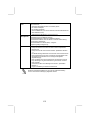
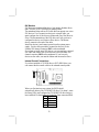
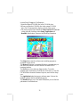
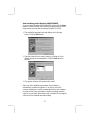
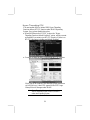
Notice:
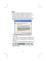
1.Owing to Microsoft’s certifying schedule is various to every
supplier, we might have some drivers not certified yet by
Microsoft. Therefore, it might happen under Windows XP that a
dialogue box (shown as below) pop out warning you this
software has not passed Windows Logo testing to verify its
compatibility with Windows XP. Please rest assured that our RD
department has already tested and verified these drivers. Click
the “Continue Anyway” button and go ahead the installation.
2. USB 2.0 Driver Limitations:
2-1.The USB 2.0 driver only supports Windows XP and
Windows 2000.
2-2.If you connect a USB 2.0 hub to the root hub, plugging USB
devices into this hub, the system might not successfully execute
certain USB devices’ connection because it could not recognize
these devices.
Currently, we are working on such limitations’ solution. As soon
as the solution is done, the updated USB drive will be released
to our website: www.pcchips.com.tw
for your downloading.
3. Note: While you are connecting power connectors, you must
first connect the CPU Vcore power connector PJ1, and then
the ATX1 connector.
IV
Page is loading ...
Page is loading ...
Page is loading ...
Page is loading ...
Page is loading ...
Page is loading ...
Page is loading ...
Page is loading ...
Page is loading ...
Page is loading ...
Page is loading ...
Page is loading ...

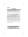
Chapter 1
Introduction
This mainboard has a Socket-478 supporting Intel
Pentium 4/Hyper Threading Technology processors with
Front-Side Bus (FSB) speeds up to 800 MHz. Hyper Threading
Technology, designed to take advantage of the multitasking
features in Windows XP, gives you the power to do more things at
once.
This mainboard integrates the 868Pro HT1683/HT1563 chipsets
that support the built-in USB 2.0 providing higher bandwidth,
implementing Universal Serial Bus Specification Revision 2.0
and is compliant with UHCI 1.1 and EHCI 0.95.
This mainboard also supports AC 97 Audio Codec and provides
Ultra DMA 33/66/100/133 function. There are one 8x AGP, one
CNR (Communications and Networking Riser) and four 32-bit
PCI slots on the mainboard. There is a full set of I/O ports
including two PS/2 ports for mouse and keyboard, one serial port,
one parallel port and maximum six USB2.0 ports – four back-panel
ports and onboard USB connectors USB3 providing four extra
ports by connecting the Extended USB Module to the mainboard.
This mainboard is an ATX mainboard and has power connectors
for an ATX power supply.
Note: You must initiate the HT CPU function through
BIOS setup. It is strongly recommended you
refer to Page 34 for relative details.

Key Features
This mainboard has these key features:
Socket-478 Processor
♦ Supports Intel Pentium 4 series CPU with Hyper
Threading Technology
♦ Supports up to 800 MHz Front-Side Bus
Hyper-Threading technology enables the operating
system into thinking it’s hooked up to two processors,
allowing two threads to be run in parallel, both on
separate ‘logical’ processors within the same physical
processor.
Chipset
The 868Pro HT1683/HT1563 chipsets provide an innovative and
scalable architecture with proven reliability and performance.
♦ 2x addressing and 4x data transferring.
♦ 64-bit data bus and 32-bit addressing.
♦ DDR SDRAM with 266,333, 400MHz.
♦ Supports AGP specification V2.0, V3.0.
♦ HyperTransportTM I/O Support, lightning bandwidth up to
1.6GB/s.
♦ PCI spec. 2.2 Compliant
♦ Provides Steerable PCI Interrupts for PCI Device Plug-
and-Play
♦ Enhanced DMA Controller
Memory Support
♦ Two 184-pin DIMM sockets for DDR SDRAM memory
modules
♦ Supports DDR400 memory bus
♦ Maximum installed memory is 2GB
AC97 Audio Codec
♦ Compliant with AC’97 2.2 specification
2

♦ Full-duplex Codec with independent and variable sampling
rate
♦ Earphone Buffer Built-In, SNR up to 90db
♦ 4Ch DAC, support 4-channel speak-out
♦ Advanced power management support
Expansion Options
The mainboard comes with the following expansion options:
♦ Four 32-bit PCI slots
♦ One 8x AGP slot
♦ One Communications Network Riser (CNR) slot
Onboard IDE
♦ Two IDE Connectors
♦ Supports PIO (Programmable Input/Output) and DMA
(Direct Memory Access) modes
♦ Supports IDE Ultra DMA bus mastering with transfer rates
of 33/66/100/133 MB/sec
Onboard I/O Ports
The mainboard has a full set of I/O ports and connectors:
♦ Two PS/2 ports for mouse and keyboard
♦ One serial port
♦ One parallel port
♦ Six USB2.0 ports (four back-panel ports, onboard USB
connector USB3 providing two extra ports
♦ Audio jacks for microphone, line-in and line-out
Fast Ethernet LAN (optional)
♦ Supports 10/100Mbps operation and half/full duplex
operation
♦ IEEE 802.3/802.3u compliant
♦ Supports IEEE 802.3u clause 28 auto negotiation
♦ Supports operation under Link Down Power Saving mode
♦ Supports Base Line Winder (BLW) compensation
♦ Adaptive Equalization
3

USB 2.0
♦ Compliant with Universal Serial Bus Specification
Revision 2.0
♦ Compliant with Intel’s Enhanced Host Controller
Interface Specification Revision 0.95
♦ Compliant with Universal Host Controller Interface
Specification Revision 1.1
♦ PCI multi-function device consists of two UHCI Host
Controller cores for full-/low-speed signaling and one
EHCI Host Controller core for high-speed signaling
♦ Root hub consists 4 downstream facing ports with
integrated physical layer transceivers shared by UHCI and
EHCI Host Controller
♦ Support PCI-Bus Power Management Interface
Specification release 1.1
♦ Legacy support for all downstream facing ports
BIOS Firmware
This mainboard uses AMI BIOS that enables users to configure
many system features including the following:
♦ Power management
♦ Wake-up alarms
♦ CPU parameters and memory timing
♦ CPU and memory timing
The firmware can also be used to set parameters for different
processor clock speeds.
Bundled Software
♦ PC-Cillin 2002 provides automatic virus protection under
Windows 98/ME/NT/2000/XP
♦ Adobe Acrobat Reader V5.0 is the software to help users
read .PDF files.
Dimensions
♦ ATX form factor of 305 x 195mm
Note: Hardware specifications and software
items are subject to change without notification.
4

Package Contents
Your mainboard package contains the following items:
The mainboard
The User’s Manual
One diskette drive ribbon cable (optional)
One IDE drive ribbon cable
The Software support CD
Optional Accessories
You can purchase the following optional accessories for this
mainboard.
The Extended USB module
The CNR v.90 56K Fax/Modem card
The Card Reader
Note: You can purchase your own optional accessories
from the third party, but please contact your local
vendor on any issues of the specification and
compatibility.
5

Chapter 2
Mainboard Installation
To install this mainboard in a system, please follow these
instructions in this chapter:
Identify the mainboard components
Install a CPU
Install one or more system memory modules
Make sure all jumpers and switches are set correctly
Install this mainboard in a system chassis (case)
Connect any extension brackets or cables to connectors on the
mainboard
Install peripheral devices and make the appropriate connections
to connectors on the mainboard
Note:
1. Before installing this mainboard, make sure jumper JP3 is
under Normal setting. See this chapter for information about
locating JP3 and the setting options.
2. Never connect power to the system during installation;
otherwise, it may damage the mainboard.
6

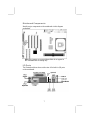
Mainboard Components
Identify major components on the mainboard via this diagram
underneath.
Note: Any jumpers on your mainboard that do not appear in
this illustration are for testing only.
I/O Ports
The illustration below shows a side view of the built-in I/O ports
on the mainboard.
(
o
p
tional
)
(shared
with
JP1
)
7

PS/2 Mouse
Use the upper PS/2 port to connect a PS/2
pointing device.
PS/2 Keyboard
Use the lower PS/2 port to connect a PS/2
keyboard.
Parallel Port
(PRN)
Use the Parallel port to connect printers or
other parallel communications devices.
COM1
Use the COM port to connect serial devices
such as mice or fax/modems. COM1 is
identified by the system as COM1.
LAN Port
(optional)
Connect an RJ-45 jack to the LAN port to
connect your computer to the Network.
USB Ports
Use the USB ports to connect USB devices.
Note: The lower USB port located near the
Parallel port is shared with the JP1 connector.
Audio Ports
Use the three audio ports to connect audio
devices. The first jack is for stereo Line-In
signal. The second jack is for stereo Line-
Out signal. The third jack is for Microphone.
Installing the Processor
This mainboard has a Socket 478 processor socket. When choosing
a processor, consider the performance requirements of the system.
Performance is based on the processor design, the clock speed and
system bus frequency of the processor, and the quantity of internal
cache memory and external cache memory.
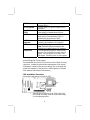
CPU Installation Procedure
Follow these instructions to install the CPU:
SOCKET
-
478
Pin 1
CPUFAN1
1
1. Unhook the locking lever of the CPU socket. Pull
the locking lever away from the socket and raising
it to the upright position.
8

2. Match the pin1 corner marked as the beveled edge
on the CPU with the pin1 corner on the socket.
Insert the CPU into the socket. Do not use force.
3. Push the locking lever down and hook it under the
latch on the edge of socket.
4. Apply thermal grease to the top of the CPU.
5. Install the cooling fan/heatsink unit onto the CPU,
and secure them all onto the socket base.
6. Plug the CPU fan power cable into the CPU fan
connector (CPUFAN1) on the mainboard.
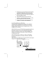
Installing Memory Modules
This mainboard accommodates two 184-pin 2.5V unbuffered
Double Data Rate SDRAM (DDR SDRAM) Dual Inline
Memory Module (DIMM) sockets, and supports up to 2.0 GB
of 400 MHz DDR SDRAM.
DDR SDRAM is a type of SDRAM that supports data transfers on
both edges of each clock cycle (the rising and falling edges),
effectively doubling the memory chip’s data throughput. DDR
DIMMs can synchronously work with 133 MHz, 166 MHz or
200 MHz memory bus.
DDR SDRAM provides 1.6 GB/s, 2.1 GB/s or 3.2GB/s data
transfer rate when the bus is 133 MHz, 166 MHz or 200 MHz,
respectively.
DDR SDRAM uses additional power and ground lines and requires
184-pin 2.5V unbuffered DIMM module.
DDR1
DDR2
9

Memory Module Installation Procedure
These modules can be installed with up to 2 GB system memory.
Refer to the following to install the memory module.
1. Push down the latches on both sides of the DIMM
socket.
2. Align the memory module with the socket. There is
a notch on the DIMM socket that you can install the
DIMM module in the correct direction. Match the
cutout on the DIMM module with the notch on the
DIMM socket.
3. Install the DIMM module into the socket and press
it firmly down until it is seated correctly. The
socket latches are levered upwards and latch on to
the edges of the DIMM.
4. Install any remaining DIMM modules.
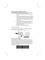
Jumper Settings
Connecting two pins with a jumper cap is SHORT; removing a
jumper cap from these pins, OPEN.
JP3
1
JP3: Clear CMOS Jumper
Use this jumper to clear the contents of the CMOS memory. You
may need to clear the CMOS memory if the settings in the Setup
Utility are incorrect and prevent your mainboard from operating.
To clear the CMOS memory, disconnect all the power cables from
the mainboard and then move the jumper cap into the CLEAR
setting for a few seconds.
Function Jumper Setting
Clear CMOS Short Pins 1-2
Normal Short Pins 2-3
10

Install the Mainboard
Install the mainboard in a system chassis (case). The board is an
ATX size mainboard. You can install this mainboard in an ATX
case. Make sure your case has an I/O cover plate matching the
ports on this mainboard.
Install the mainboard in a case. Follow the case manufacturer’s
instructions to use the hardware and internal mounting points on
the chassis.
PJ1
1
SW1
1
SYSFAN1
1
A
TX1
Connect the power connector from the power supply to the ATX1
connector on the mainboard. PJ1 is the CPU Vcore power
connector.
Note: While you are connecting power connectors, you must first
connect the CPU Vcore power connector PJ1, and then the
ATX1 connector.
If there is a cooling fan installed in the system chassis, connect the
cable from the cooling fan to the SYSFAN1 fan power connector
on the mainboard.
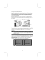
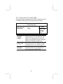
Connect the case switches and indicator LEDs to the SW1
connector. Here is a list of the SW1 pin assignments.
Pin Signal Pin Signal
1 HD_LED_P 2 FP PWR/SLP
3 HD_LED_N 4 FP PWR/SLP
5 RESET_SW_N 6 POWER_SW_P
7 RESET_SW_P 8 POWER_SW_N
9 RSVD_DNU 10 KEY
11

Connecting Optional Devices
Refer to the following for information on connecting the
mainboard’s optional devices:
IR1
1
1
JP1
A
UDIO1
1
1
USB3
SPK1
1
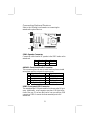
SPK1: Speaker Connector
Connect the cable from the PC speaker to the SPK1 header on the
mainboard.
Pin Signal Pin Signal
1 SPKR 2 NC
3 GND 4 +5V
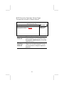
AUDIO1: Front Panel Audio Connector
This connector allows the user to install auxiliary front-oriented
microphone and line-out ports for easier access.
Pin Signal Pin Signal
1 AUD_MIC 2 AUD_GND
3 AUD_MIC_BIAS 4 AUD_VCC
5 AUD_FPOUT_R 6 AUD_RET_R
7 HP_ON 8 KEY
9 AUD_FPOUT_L 10 AUD_RET_L
USB3: Front panel USB Connector
The mainboard has USB ports installed on the rear edge I/O port
array. Additionally, some computer cases have USB ports at the
front of the case. If you have this kind of case, use auxiliary USB
connectors USB3 to connect the front-mounted ports to the
mainboard.
12

Pin Signal Pin Signal
1 VERG_FP_USBPWR0 2 VERG_FP_USBPWR0
3 USB_FP_P0- 4 USB_FP_P1-
5 USB_FP_P0+ 6 USB_FP_P1+
7 GROUND 8 GROUND
9 KEY 10 USB_FP_OC0
1. Locate the USB3 connector on the mainboard.
2. Plug the bracket cable onto the USB3 connector.
3. Remove a slot cover from one of the expansion slots on the
system chassis. Install an extension bracket in the opening.
Secure the extension bracket to the chassis with a screw.
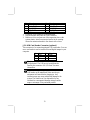
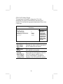
JP1: USB Card Reader Connector (optional)
This connector is for connecting internal USB card reader. You can
use a card reader to read or transfer files and digital images to your
computer.
Pin Signal Pin Signal
1 VCC 2 USB-
3 USB+ 4 GND
5 KEY
The JP1 is shared with one of the USB ports of the
I/O back panel. The USB port is located near the
Parallel port connector. See “I/O Ports” for more
information.
Please check the pin assignment of the cable and the
USB header on the mainboard. Make sure the pin
assignment will match before plugging in. Any
incorrect usage may cause unexpected damage to the
system. The vendor won’t be responsible for any
incidental or consequential damage arising from the
usage or misusage of the purchased product.
13

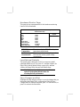
IR1: Infrared Port
The infrared port allows the wireless exchange of information
between your computer and similarly equipped devices such as
printers, laptops, Personal Digital Assistants (PDAs), and other
computers.
Pin Signal Pin Signal
1 NC 2 KEY
3 +5V 4 GND
5 IRTX 6 IRRX
1. Locate the infrared port IR1 connector on the mainboard.
2. If you are adding an infrared port, connect the ribbon cable
from the port to the IR1 connector and then secure the port to
an appropriate place in your system chassis.
Install Other Devices
Install and connect any other devices in the system following the
steps below.
1
1
IDE1
FDC1
IDE2
1
Floppy Disk Drive
The mainboard ships with a floppy disk drive cable that can
support one or two drives. Drives can be 3.5” or 5.25” wide, with
capacities of 360K, 720K, 1.2MB, 1.44MB, or 2.88MB.
Install your drives and connect power from the system power
supply. Use the cable provided to connect the drives to the floppy
disk drive connector FDC1.
14

IDE Devices
IDE devices include hard disk drives, high-density diskette drives,
and CD-ROM or DVD-ROM drives, among others.
The mainboard ships with an IDE cable that can support one or two
IDE devices. If you connect two devices to a single cable, you
must configure one of the drives as Master and one of the drives as
Slave. The documentation of the IDE device will tell you how to
configure the device as a Master or Slave device. The Master
device connects to the end of the cable.
Install the device(s) and connect power from the system power
supply. Use the cable provided to connect the device(s) to the
Primary IDE channel connector IDE1 on the mainboard.
If you want to install more IDE devices, you can purchase a second
IDE cable and connect one or two devices to the Secondary IDE
channel connector IDE2 on the mainboard. If you have two
devices on the cable, one must be Master and one must be Slave.
Internal Sound Connections
If you have installed a CD-ROM drive or DVD-ROM drive, you
can connect the drive audio cable to the onboard sound system.
CD1
1
When you first start up your system, the BIOS should
automatically detect your CD-ROM/DVD drive. If it doesn’t, enter
the Setup Utility and configure the CD-ROM/DVD drive that you
have installed. On the mainboard, locate the 4-pin connector CD1.
Pin Signal
1 CD IN L
2 GND
3 GND
4 CD IN R
15

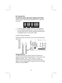
Expansion Slots
This mainboard has one AGP, one CNR and four 32-bit PCI slots.
A
GP1
CNR1
PCI4 PCI3 PCI2 PCI1
Follow the steps below to install an AGP/CNR/PCI expansion card.
1. Locate the AGP, CNR or PCI slots on the mainboard.
2. Remove the blanking plate of the slot from the system chassis.
3. Install the edge connector of the expansion card into the slot.
Ensure the edge connector is correctly seated in the slot.
4. Secure the metal bracket of the card to the system chassis with
a screw.
8x AGP Slot
You can install a graphics adapter that supports the 8x AGP
specification and has a 8x AGP edge connector in the AGP slot.
CNR Slot
You can install the CNR (Communications and Networking Riser)
cards in this slot, including LAN, Modem, and Audio functions.
PCI Slots
You can install the 32-bit PCI interface expansion cards in the slots.
16
Page is loading ...
Page is loading ...
Page is loading ...
Page is loading ...
Page is loading ...
Page is loading ...
Page is loading ...
Page is loading ...
Page is loading ...
Page is loading ...
Page is loading ...
Page is loading ...
Page is loading ...
Page is loading ...
Page is loading ...
Page is loading ...
Page is loading ...
Page is loading ...
-
 1
1
-
 2
2
-
 3
3
-
 4
4
-
 5
5
-
 6
6
-
 7
7
-
 8
8
-
 9
9
-
 10
10
-
 11
11
-
 12
12
-
 13
13
-
 14
14
-
 15
15
-
 16
16
-
 17
17
-
 18
18
-
 19
19
-
 20
20
-
 21
21
-
 22
22
-
 23
23
-
 24
24
-
 25
25
-
 26
26
-
 27
27
-
 28
28
-
 29
29
-
 30
30
-
 31
31
-
 32
32
-
 33
33
-
 34
34
-
 35
35
-
 36
36
-
 37
37
-
 38
38
-
 39
39
-
 40
40
-
 41
41
-
 42
42
-
 43
43
-
 44
44
-
 45
45
-
 46
46
-
 47
47
-
 48
48
-
 49
49
-
 50
50


PC CHIPS M916 (V1.3a) Specification
- Category
- Motherboards
- Type
- Specification
Ask a question and I''ll find the answer in the document
Finding information in a document is now easier with AI
Related papers
-
PC CHIPS M810DG (V8.0a) User manual
-
-
-
-
-
-
ECS T12 (V1.0a) User manual
-
-
-
ECS M985G Series User manual
Other documents
-
Canyon CNR-USBHUB06N Datasheet
-
-
MATSONIC MS9317E Series User manual
-
-
-
-
Longshine LCS-8038TXI Datasheet
-
-
BELGACOM M800LMR User manual
-
 ANTAIRA USB-HUB4K Installation guide
