Page is loading ...

Questions, problems, missing parts? Before returning to your retailer, call our customer
service department at 1-800-643-0067, 8 a.m. - 6 p.m., EST, Monday - Thursday, 8 a.m. - 5 p.m.,
EST, Friday. p.m., EST, Monday - Friday.
1
ATTACH YOUR RECEIPT HERE
Serial Number _________________________ Purchase Date _________________________
Lowes.com/harborbreeze
Harbor Breeze® is a registered trademark
of LF, LLC. All Rights Reserved.
XXXXX
ITEM #0044687, 0043676, 0044622
CROSSWINDS CEILING FAN
MODEL #40093, 40091, 40092
Español p. 25

2
Lowes.com/harborbreeze
TABLE OF CONTENTS
Package Contents .................................................................3
Hardware Contents ................................................................4
Safety Information .................................................................5
Preparation ......................................................................6
Initial Installation ..................................................................7
Standard or Angle Mounting Instructions. . . . . . . . . . . . . . . . . . . . . . . . . . . . . . . . . . . . . . . . . . . . . . . . 9
Closemount Instructions ...........................................................12
Wiring .........................................................................13
Final Installation. . . . . . . . . . . . . . . . . . . . . . . . . . . . . . . . . . . . . . . . . . . . . . . . . . . . . . . . . . . . . . . . . . 14
Operating Instructions .............................................................19
Care and Maintenance ............................................................21
Troubleshooting ..................................................................21
Limited Lifetime Warranty ..........................................................23
Replacement Parts List ............................................................24

3
Lowes.com/harborbreeze
PACKAGE CONTENTS
A
I
OQ
J
KL
M
N
G
C
H
D
E
F
P
R
B
S
PART DESCRIPTION QUANTITY
A Downrod 1
B Plastic Plug Button (preassembled to Switch Housing Cap (Q)) 1
C Canopy (preassembled to the Mounting Bracket (D)) 1
D Mounting Bracket 1
E Light Kit 1
F Motor Assembly 1
G Blade Arm 5
H Blade 5
I Bowl 1
J Bulb 3
K End Cap (preassembled to Light Kit (E)) 1
L Finial (preassembled to Light Kit (E)) 1
M Canopy Cover (preassembled to Canopy (C)) 1
N Remote Control 1
O 12-Volt Battery 1
P Switch Housing (preassembled to Motor Assembly (F)) 1
Q Switch Housing Cap 1
R Receiver 1
S Yoke Cover 1

4
Lowes.com/harborbreeze
HARDWARE CONTENTS
Motor Screw
Qty. 10
(preassembled to
Motor Assembly
(F)) + 1 extra
Wire
Connector
Qty. 5
+ 1 extra
Pull Chain
Extension
Qty. 2
Downrod Clip
Qty. 1
(preassembled to
Downrod (A))
Downrod Pin
Qty. 1
(preassembled to
Downrod (A))
Motor Housing Set
Screw
Qty. 2
(preassembled to
Motor Assembly (F))
Closemount Screw
Qty. 3
(preassembled to
Motor Assembly (F))
+ 1 extra
Mounting Bracket
Screw
Qty. 4
(preassembled to
Mounting Bracket
(D))
Switch Housing
Screw
Qty. 3
(preassembled to
Switch Housing
Cap (Q))
Rubber Washer
Qty. 1
(preassembled to
Light Kit (E))
Nut
Qty. 2
(preassembled to
Light Kit (E))
AA BB CC DD EE
FF
KK
GG
HH II JJ

5
Lowes.com/harborbreeze
SAFETY INFORMATION
Please read and understand this entire manual before attempting to assemble, operate, or install the
product.
• Before you begin installing the fan, disconnect the power by removing fuses or turning off the circuit
breakers.
• Make sure that all electrical connections comply with local codes, ordinances, the National
ElectricalCode,andANSI/NFPA70-199.Hireaqualiedelectricianorconsultado-it-yourself
wiring handbook if you are unfamiliar with installing electrical wiring.
• Make sure the installation site you choose allows a minimum clearance of 7 ft. from the blades to
theoorandatleast30in.fromtheendofthebladestoanyobstruction.
• The net weight of this fan is: 18.04 lbs.
DANGER: When using an existing outlet box, make sure the outlet box is securely attached to
the building structure and can support the full weight of the fan. Failure to do this can result in serious
injury or death. The stability of the outlet box is essential in minimizing wobble and noise in the fan
after installation is complete.
WARNING: To avoid personal injury, the use of gloves may be necessary while handling fan
parts with sharp edges.
WARNING: Using a full-range dimmer switch to control fan speed will cause a loud humming
noisefromthefan.Toreducetheriskofreorelectricshock,doNOTuseafull-rangedimmerswitch
to control the fan speed.
WARNING: Toreducetheriskofre,electricshock,orpersonalinjury,mountthefantoan
outlet box marked “ACCEPTABLE FOR FAN SUPPORT” and use the mounting screws provided with
theoutletbox.Mostoutletboxescommonlyusedforthesupportoflightingxturesarenotacceptable
forfansupportandmayneedtobereplaced.Consultaqualiedelectricianifindoubt.Securethe
outlet box directly to the building structure. The outlet box and its support must be able to support the
moving weight of the fan (at least 35 lbs.). Do NOT use a plastic outlet box.
WARNING: Toreducetheriskofre,electricalshock,orpersonalinjury,wireconnectors
provided with this fan are designed to accept only one 12-gauge house wire and two lead wires from
the fan. If your house wire is larger than 12 gauges or there is more than one house wire to connect
to the two fan lead wires, consult an electrician for the proper size wire connectors to use.
WARNING: Toreducetheriskofreorelectricshock,donotusethefanwithanysolid-state
speed-control device or control the fan speed with a full-range dimmer switch.
WARNING: Toreducetheriskofre,electricshock,orpersonalinjury,donotbendtheblade
arms when installing them, balancing the blades, or cleaning the fan. Do not insert objects between
the rotating fan blades.
WARNING: To reduce the risk of personal injury, use only parts provided with this fan. The use
of parts OTHER than those provided with this fan will void the warranty.

6
Lowes.com/harborbreeze
SAFETY INFORMATION
CAUTION: Read all instructions and safety information before installing your new fan. Review the
accompanying assembly diagrams.
CAUTION: Be sure the outlet box is properly grounded or that a ground (green or bare) wire is present.
CAUTION: Carefully check all screws, bolts, and nuts on the fan motor assembly to ensure that they
are secured.
CAUTION: This equipment has been tested and found to comply with the limits for a Class B digital
device, pursuant to Part 15 of the FCC Rules. These limits are designed to provide reasonable
protection against harmful interference in a residential installation. This equipment generates,
uses and can radiate radio frequency energy and, if not installed and used in accordance with the
instructions, may cause harmful interference to radio communications.
PREPARATION
Before beginning the assembly of this product, ensure all parts are present. Compare all parts with
the package contents list and hardware contents list. If any part is missing or damaged, do not
attempt to assemble the product.
After opening the top of the carton, remove the mounting hardware package from the foam inserts,
then remove the motor from the packaging and place it on a soft surface, such as a carpet, to avoid
damagetothenish.
Estimated Assembly Time: 120 minutes
Tools Required for Assembly (not included): Electrical Tape, Phillips Screwdriver, Pliers, Safety
Glasses, Step Ladder, and Wire Strippers
Helpful Tools (not included): AC Tester Light, Tape Measure, Wiring Handbook and Wire Cutters

7
Lowes.com/harborbreeze
INITIAL INSTALLATION
1. Turn off the circuit breakers and the wall switch to the
fan supply line leads.
DANGER: Failure to disconnect the power
supply prior to installation may result in serious injury
or death.
1
2. Determine the mounting method to use.
Note: Flushmount installation is not available for this
item.
Important: If using the angle mount, check to ensure
the ceiling angle is not steeper than 25°.
2
Downrod Mounting
Flushmount Closemount
Angle Mounting
3. Ensure the blades (H) will be at least 30 in. from
any obstructions. Also check the downrod (A) length
to ensure the blades (H) will be at least 7 ft. above
theoor.
A
H
3
7 ft. min.
30 in. min.

8
Lowes.com/harborbreeze
INITIAL INSTALLATION
4. Remove the two mounting bracket screws (HH) from
the round holes of the canopy (C). Set aside for later
use. Detach mounting bracket (D) from canopy (C).
Secure the mounting bracket (D) to the outlet box
(not included) using screws and washers provided
with the outlet box.
Note: It is very important you use the proper
hardware when installing the mounting bracket
(D) as this will support the fan.
Important: If using the angle mount, ensure the
open end of the mounting bracket (D) is installed
facing the higher point of the ceiling.
Hardware Used
HH
Mounting
Bracket Screw
x 2
D
4
C
HH
D
5. Remove the motor screws (AA) from the underside of
the motor assembly (F).
Note: If there are plastic motor blocks installed,
discard them but keep the motor screws (AA).
Hardware Used
AA
Motor Screw x 10
AA
5
Motor Block
F
For Standard or Angle Mounting Instructions,
continue to page 9. For Closemount Instructions,
proceed to page 12.

9
Lowes.com/harborbreeze
STANDARD OR ANGLE MOUNTING INSTRUCTIONS
1. Remove the downrod pin (EE) and downrod clip
(DD) from the downrod (A). Then partially loosen the
motor-housing set screws (FF) in the yoke at the top
of the motor assembly (F).
Helpful Hint: Downrod style mounting is best suited
for ceilings 8 ft. or higher. For taller ceilings you may
want to use a longer downrod (not included). Angle
style mounting is best suited for angled or vaulted
ceilings. A longer downrod is sometimes necessary
to ensure proper blade clearance.
Hardware Used
DD
Downrod Clip x 1
EE
Downrod Pin x 1
FF
Motor Housing
Set Screw
x 2
F
A
DD
EE
FF
A
1
2. Insert the downrod (A) through the canopy (C) and
yoke cover (S). Thread the wires from the motor
housing (F) through the downrod (A).
A
C
S
F
2

10
Lowes.com/harborbreeze
STANDARD OR ANGLE MOUNTING INSTRUCTIONS
3. Slide the downrod (A) into the yoke of the motor
assembly (F), align the holes, and re-install the
downrod clip (DD) and downrod pin (EE). Then
tighten the motor housing set screws (FF).
Hardware Used
DD
Downrod Clip x 1
EE
Downrod Pin x 1
FF
Motor Housing
Set Screw
x 2
DD
FF
A
F
EE
3
4. Depending on the length of downrod you use, you
may need to cut the lead wires back to simplify the
wiring. If you decide to cut back the lead wires, it is
suggested that you do so in the following manner:
Take the lead wires and make sure that you have
pulled them all the way through the top of the
downrod and measure 8 in. of lead wire, and then cut
the excess wire off with wire cutters.
4

11
Lowes.com/harborbreeze
STANDARD OR ANGLE MOUNTING INSTRUCTIONS
5. If you decided to cut back the lead wire in Step 4,
strip 1/2 in. of insulation from the end of the white
wire. Twist the stripped ends of each strand of wire
within the insulation with pliers. Repeat this step for
black, blue (if applicable) and green wires.
Important: If you did not cut back the lead wires in
Step 4, Step 5 is not necessary and you
may proceed to Step 6.
5
6. Install the ball end of the downrod (A) into the mounting
bracket (D) opening. Align the slot in the ball with the
tab in the mounting bracket (D). The rod should not
rotate if it is done correctly.
DANGER: Failure to align the slot in the ball
with the tab may result in serious injury or death.
D
A
6
7. Insert the receiver (R) into the mounting bracket (D)
withtheatsideofthereceiver(R)facingtheceiling.
Proceed to Wiring, page 13.
D
R
7

12
Lowes.com/harborbreeze
CLOSEMOUNT INSTRUCTIONS
1. Remove the canopy cover (M) from the bottom of the
canopy (C).
Helpful Hint: Closemount-style mounting is more
suitable for ceilings lower than 8 ft. high. The
downrod (A) and canopy cover (M) are not used in
this type of installation.
1
M
C
2. Align the canopy (C) with the holes in the top of the
motor assembly (F). Secure the canopy (C) to the
top of the motor assembly (F) with the closemount
screws (GG).
Hardware Used
GG
Closemount Screw x 3
F
C
GG
2
3. Raise the fan and place the canopy (C) on the hook
of the mounting bracket (D).
C
D
3

13
Lowes.com/harborbreeze
WIRING
WARNING:Toreducetheriskofre,electricalshock,orpersonalinjury,wireconnectors
provided with this fan are designed to accept only one 12-gauge house wire and two lead wires from
the fan. If your house wire is larger than 12 gauges and there is more than one house wire to connect
to the two fan lead wires, consult an electrician for the proper size wire connectors to use.
WARNING: If the house wires are different colors than referred to in the following step, stop
immediately. A professional electrician is recommended to determine the correct wiring scheme.
CAUTION: Be sure the outlet box is properly grounded or that a Ground (Green or Bare) wire is present.
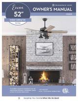
1. Connect with supply and fan wires according to the
diagram and these steps:
•ConnecttheGreen/Groundwirefromthedownrod
and the Green/Ground wire from the mounting
bracket (D) to the Bare/Ground supply wire.
•ConnecttheRedwirefromthereceiver(R)tothe
supply Black wire.
•ConnecttheBlackwirefromthereceiver(R)tothe
Black wire from the fan.
•ConnecttheWhitewirefromthereceiver(R)tothe
supply White wire.
•ConnecttheWhitewirefromthereceiver(R)tothe
White wire from the fan.
•ConnecttheBluewirefromthereceiver(R)tothe
Blue wire from the fan.
•Secureallwiringconnectionstogetherwithwire
connectors (BB).
Note: The Red wire is hot power for the fan. The Blue
wire is hot power for the light kit. The White wire is
common for the fan and light kit. The Green wire
is the grounded wire. If house wires are different
colors than referred to above, stop immediately. It is
recommended a professional electrician determines
the proper wiring.
Hardware Used
BB
Wire Connector x 5
Receiver
Fan
Black
Black
Blue
White
Ground/Green
White
1
Red
2. Wrap electrical tape (not included) around each
individual wire connector (BB) down to the wire.
Hardware Used
BB
Wire Connector x 5
BB
2

14
Lowes.com/harborbreeze
WIRING
3. Turn the spliced/taped wires upward and gently push
the wires and wire connectors (BB) into the outlet box.
WARNING: Ensure that no bare wire or wire
strands are visible after making connections. Place
the Green and White wire connections on opposite
sides of the outlet box from the Black and Blue (if
applicable) wire connections.
BB
3
FINAL INSTALLATION
1. Remove the two mounting bracket screws (HH) from
the mounting bracket (D) and loosen the other two
screws about 1/4 in. Then align the canopy (C) up to
the ceiling over the loose mounting bracket screws
(HH). Place the keyholes of the canopy (C) into the
screws (HH) and rotate clockwise.
Hardware Used
HH
Mounting Bracket
Screw
x 2
B
HH
1
2. Secure the canopy (C) with the previously removed
mounting bracket screws (HH) and securely tighten
all four screws (HH).
Note: Closemount installation will not have the
downrod (A) and canopy cover (M).
Hardware Used
HH
Mounting Bracket
Screw
x 4
B
J
HH
A
II
2

15
Lowes.com/harborbreeze
FINAL INSTALLATION
3. Align the holes in a blade (H) over the locating
pins on a blade arm (G). Push the pins through
the blade and twist the lock on the blade arm (G)
counterclockwise to secure the blade (H).
3
G
H
4. Align the holes of one blade arm (G) with two holes
on the motor assembly (F) and attach with two
motor screws (AA) previously removed (Step 5,
page 8). Securely tighten the motor screws (AA)
with a Phillips screwdriver. Repeat this step for the
remaining blade arms (G).
Hardware Used
AA
Motor Screw x 10
4
AA
F
G

16
Lowes.com/harborbreeze
FINAL INSTALLATION
Note: If you wish to install the fan without the light kit,
proceed to step 13.
5. Remove the nut (KK) from the rod on light kit (E).
Remove the switch housing screws (II) and the plastic
plug button (B) from the switch housing cap (Q).
Hardware Used
II
Switch Housing
Screw
x 3
Nut x 1
5
E
KK
Q
B
II
6. Assemble the switch housing cap (Q) to the rod on
top of the light kit (E). Secure with nut (KK).
Hardware Used
Nut x 1
7. Connect the white wire from the switch housing
(P) to the white wire from the light kit (E). Connect
the blue wire from the switch housing (P) to the
black wire from the light kit (E). Ensure the wire
connections are secure.
P
E
7
KK
6
Q
E
KK
KK

17
Lowes.com/harborbreeze
FINAL INSTALLATION
8. Assemble the light kit (E) to the switch housing (P) using
the previously removed switch housing screws (II).
Hardware Used
II
Switch Housing
Screw
x 3
P
E
II
8
9. Install the bulbs (J) into the sockets on the light kit (E).
IMPORTANT: Make sure you allow the bulbs (J) and
light kit (E) to cool before you replace the bulbs.
Note: The fan comes with a 190W limiter. When the
total wattage of the lights is over 190W, the lights
do not work. Please replace the bulbs with lower
wattage bulbs.
E
J
9
10. Remove the pre-installed rubber washer (JJ), nut (KK),
endcap(K)andnial(L)fromthelightkit(E).
Hardware Used
JJ
Rubber
Washer
x 1
KK
Nut x 1
E
10
K
L
JJ
KK

18
Lowes.com/harborbreeze
11. Feed pull chain coming from the center of the light
kit (E) through the center hole in the glass shade (I).
Feed the pull chain coming from the switch housing
(P) through the off-center hole in the glass shade (I).
Re-install rubber washer (JJ) and secure with nut (KK).
Feed the pull chains through the appropriate holes in
thenialplate(K)andtheholeinthenial(L),thenlift
thenialplate(K)upuntilitisushwiththeglassshade
(I).Screwthenial(L)ontothethreadedrodofthelight
kit (E) to secure.
Hardware Used
JJ
Rubber
Washer
x 1
KK
Nut x 1
I E
K
L
JJ
KK
11
12. Attach the pull chain extensions (CC) or custom pull
chains extensions (not included) to the fan and light
pull chains.
Assembly is now complete.
Hardware Used
CC
Pull Chain
Extension
x 2
13. If you do not wish to use the light kit, push the wires
back up into the switch housing (P) and install the
switch housing cap (Q) using the switch housing
screws (II). Attach the appropriate pull chain extension
(CC) to fan pull chain. Discard the remaining pull chain
extension (CC).
Hardware Used
CC
Pull Chain
Extension
x 1
Switch
Housing Screw
x 2
P
Q
CC
II
H
a
r
b
o
r
B
r
e
e
z
e
13
FINAL INSTALLATION
II
H
a
r
b
o
r
B
r
e
e
z
e
H
a
r
b
o
r
B
r
e
e
z
e
H
a
r
b
o
r
B
r
e
e
z
e
12
CC

19
Lowes.com/harborbreeze
OPERATING INSTRUCTIONS
1. The pull chain labeled FAN has four positions to
control fan speed. One pull is HIGH, two is MEDIUM,
three is LOW and four turns the fan OFF.
1
2. Use the fan reverse switch, located on the switch
housing (P) to optimize your fan for seasonal
performance.
Using a ceiling fan will allow you to raise your
thermostat setting in summer and lower your
thermostat setting in winter without feeling a
difference in your comfort.
Note: Wait for the fan to stop before moving the
reverse switch.
2A. In warmer weather, push the reverse switch down
to display a Sun icon, which will result in downward
airowcreatingawindchilleffect.
2B. In cooler weather, push the reverse switch up to
displayaSnowakeicon,whichwillresultinupward
airowthatcanhelpmovestagnant,hotairoffthe
ceiling area.
Important: The reverse switch must be set either
completely up or down in order for the fan
to function correctly. If the reverse switch
is set in the middle position, the fan will
not operate Fig. 2C.
Fig. 2A Fig. 2B
Fig. 2C
P
2

20
Lowes.com/harborbreeze
OPERATING INSTRUCTIONS
3. Remove the battery cover from the back of the
remote control (N) and insert the 12-volt battery (O).
Replace the battery cover.
D/CFL Switch: Located inside the battery
compartment in remote control (N), this switch should
be moved from “D” for dimmer or “CFL” for compact
uorescentbulbsdependingonwhichtypeofbulbs
you’ve installed in the fan. Note the switch is pre-set
to “D” to correspond with the included incandescent
bulbs.
IMPORTANT: The dimmer function does not work
with CFL bulbs.
N
O
O P
3
4. To operate the fan using remote control (N), press
and release the following buttons:
1 - High fan speed
2 - Medium fan speed
3 - Low fan speed
4 - Turns the fan off. Press and hold this button for
5 seconds to enter Light Delay Off mode, which will
turn off light after one minute. The LED on the remote
control(N)willashfourtimestoconrmmodesetting.
5 - Turns the light on and off. Press and hold this
button to dim or brighten the lights.
N
O P
1
2
3
4
5
4
/