Page is loading ...
30" (76.2 CM) AND 36" (91.4 CM) RANGE HOOD
For questions about features, operation/performance, parts, accessories or service, call: 1-800-253-1301
or visit our website at www, whirlpool,com
In Canada, for assistance, installation and service, call 1-800-807-6777 or visit our website at www, whirlpool,ca
HOTTED'ASPIRATIONDE
30"(76,2 CM) ET36"(91,4 CM)
Au Canada, pour assistance, installation ou service, composer
le 1-800-807-6777 ou visiter notre site Web
www.whirlpool.ca
Table of Contents/Table des matieres ............................................................................. 2
J
Models/ModUles:
UXT5230AY/UXT5236AY
IMPORTANT: READ AND SAVE THESE INSTRUCTIONS.
FOR RESIDENTIAL USE ONLY.
IMPORTANT : LIRE ET CONSERVER CES INSTRUCTIONS.
POUR UTILISATION RC:SIDENTIELLE UNIQUEMENT.
LI3Z5C/W10400323E

TABLEOF CONTENTS TABLEDESMATIERES
RANGE HOOD SAFETY ................................................................. 2
INSTALLATION REQUIREMENTS ................................................ 4
Tools and Parts ............................................................................ 4
Location Requirements ................................................................ 4
Venting Requirements .................................................................. 5
Electrical Requirements ............................................................... 6
INSTALLATION INSTRUCTIONS .................................................. 7
Prepare Location .......................................................................... 7
Install Range Hood ....................................................................... 9
Make Electrical Connection ....................................................... 11
Complete Installation ................................................................. 11
RANGE HOOD USE ...................................................................... 12
Range Hood Controls ................................................................ 12
RANGE HOOD CARE ................................................................... 12
Cleaning ...................................................................................... 12
WIRING DIAGRAM ....................................................................... 14
ASSISTANCE OR SERVICE ......................................................... 15
In the U.S.A................................................................................ 15
In Canada ................................................................................... 15
Accessories ................................................................................ 15
WAR RANTY .................................................................................. 16
SECURITE DE LA HOTTE DE CUlSINIERE ................................ 17
EXIGENCES D'INSTALLATION ................................................... 19
Outils et pieces ........................................................................... 19
Exigences d'emplacement ......................................................... 19
Exigences concernant I'evacuation ........................................... 20
Specifications electriques .......................................................... 22
INSTRUCTIONS D'INSTALLATION ............................................. 22
Preparation de I'emplacement ................................................... 22
Installation de la hotte ................................................................ 24
Raccordement electrique ........................................................... 27
Achever I'installation.................................................................. 27
UTILISATION DE LA HOTTE ....................................................... 28
Commandes de la hotte de cuisiniere ....................................... 28
ENTRETIEN DE LA HO'R'E .......................................................... 28
Nettoyage ................................................................................... 28
SCHleMA DE CABLAGE ............................................................... 30
ASSISTANCE OU SERVICE ......................................................... 31
Au Canada .................................................................................. 31
Accessoires ................................................................................ 31
GARANTIE ..................................................................................... 31
RANGE HOOD SAFETY
Your safety and the safety of others are very important.
We have provided many important safety messages in this manual and on your appliance. Always read and obey all safety
messages.
This is the safety alert symbol.
This symbol alerts you to potential hazards that can kill or hurt you and others.
All safety messages will follow the safety alert symbol and either the word "DANGER" or "WARNING."
These words mean:
You can be killed or seriously injured if you don't immediately
follow instructions.
You can be killed or seriously injured if you don't follow
instructions.
All safety messages will tell you what the potential hazard is, tell you how to reduce the chance of injury, and tell you what can
happen if the instructions are not followed.
2

iMPORTANT SAFETY iNSTRUCTiONS
WARNING: TO REDUCE THE RISK OF FIRE, ELECTRIC
SHOCK, OR INJURY TO PERSONS, OBSERVE THE
FOLLOWING:
[] Use this unit only inthe manner intended by the
manufacturer. Ifyou have questions, contact the
manufacturer.
[] Before servicing or cleaning the unit, switch power off at
service panel and lock the service disconnecting means to
prevent power from being switched on accidentally. When
the service disconnecting means cannot be locked,
securely fasten a prominent warning device, such as a tag,
to the service panel.
[] Installation work and electrical wiring must be done by
qualified person(s) in accordance with all applicable codes
and standards, including fire-rated construction.
[] Do not operate any fan with a damaged cord or plug.
Discard fan or return to an authorized service facility for
examination and/or repair.
[] Sufficient air is needed for proper combustion and
exhausting of gases through the flue (chimney) of fuel
burning equipment to prevent backdrafting. Follow the
heating equipment manufacturer's guideline and safety
standards such as those published by the National Fire
Protection Association (NFPA), the American Society for
Heating, Refrigeration and Air Conditioning Engineers
(ASHRAE), and the local code authorities.
[] When cutting or drilling into wall or ceiling; do not damage
electrical wiring and other utilities.
[] Ducted fans must always be vented outdoors.
CAUTION: For general ventilating use only. Do not use
to exhaust hazardous or explosive materials and vapors.
CAUTION: To reduce risk of fire and to properly exhaust
air, be sure to duct air outside - do not vent exhaust air into
spaces within walls or ceilings, attics or into crawl spaces,
or garages.
WARNING: TO REDUCE THE RISK OF FIRE, USE ONLY
METAL DUCTWORK.
WARNING: TO REDUCE THE RISK OF A RANGE TOP
GREASE FIRE:
[] Never leave surface units unattended at high settings.
Boilovers cause smoking and greasy spillovers that may
ignite. Heat oils slowly on low or medium settings.
[] Always turn hood ON when cooking at high heat or when
flambeing food (i.e. Crepes Suzette, Cherries Jubilee,
Peppercorn Beef Flamb6).
[] Clean ventilating fans frequently. Grease should not be
allowed to accumulate on fan or filter.
[] Use proper pan size. Always use cookware appropriate for
the size of the surface element.
WARNING: TO REDUCE THE RISK OF INJURY TO
PERSONS IN THE EVENT OF A RANGE TOP GREASE
FIRE, OBSERVE THE FOLLOWING: a
[] SMOTHER FLAMES with a close fitting lid, cookie sheet, or
metal tray, then turn off the burner. BE CAREFUL TO
PREVENT BURNS. If the flames do not go out
immediately, EVACUATE AND CALL THE FIRE
DEPARTMENT.
[] NEVER PICK UP A FLAMING PAN - you may be burned.
[] DO NOT USE WATER, including wet dishcloths or towels -
a violent steam explosion will result.
[] Use an extinguisher ONLY if:
- You know you have a class ABC extinguisher, and you
already know how to operate it.
- The fire is small and contained in the area where it
started.
- The fire department is being called.
- You can fight the fire with your back to an exit.
aBased on "Kitchen Fire Safety Tips" published by NFPA.
[] WARNING: To reduce the risk of fire or electrical shock,
do not use this fan with any solid-state speed control
device.
READ AND SAVE THESE INSTRUCTIONS
INSTALLATIONREQUIREMENTS
Gather the required tools and parts before starting installation.
Read and follow the instructions provided with any tools listed
here.
Tools needed
• Drill
• 1¼" (3.0 cm) drill bit
• 1/8"(3.0 mm) drill bit for pilot holes
• Pencil
• Wire stripper or utility knife
• Tape measure or ruler
• Caulking gun and weatherproof caulking compound
• Flat-blade screwdriver
• Phillips screwdriver
• Saber or keyhole saw
• Metal snips
• Compass or 8" (20.3 cm) circle template
Parts supplied
Remove parts from package. Check that all parts are included.
• 2 - 3.5 x 5 mm screws
• 31/4'' x 10" (8.3 x 25.4 cm) rectangular damper
• T-10 Torx_t adapter
• 4- 4.5 x 13 mm mounting screws
Parts needed
• Wall or roof cap with damper to match vent system
• 3 - UL listed wire connectors
• Vent clamps/duct tape as required
For 7" (17.8 cm) round vented installations:
• 7" (17.8 cm) round metal vent system
• 7" (17.8 cm) round damper. For information on ordering, see
the "Accessories" section.
• 7" (17.8 cm) round vent mounting plate. For information on
ordering, see the "Accessories" section.
For 31/4'' x 10" (8.3 x 25.4 cm) rectangular vented installations:
• 31/4"x 10" (8.3 x 25.4 cm) rectangular metal vent system
For non-vented (recirculation) installations:
• Charcoal filter kit. For information on ordering, see the
"Accessories" section.
For cabinets with recessed bottoms:
• Two 2" (5.1 cm) wide filler strips. Length and thickness
determined by recess dimensions.
• Four flat head wood screws or machine screws with washers
and nuts (to attach filler strips).
IMPORTANT: Observe all governing codes and ordinances.
• It is the installer's responsibility to comply with installation
clearances specified on the model/serial rating plate. The
model/serial rating plate is located inside the range hood on
the left wall.
• Range hood location should be away from strong draft areas,
such as windows, doors and strong heating vents.
• Cabinet opening dimensions that are shown must be used.
Given dimensions provide minimum clearance. Consult the
cooktop/range manufacturer installation instructions before
making any cutouts.
• Grounded electrical outlet is required. See "Electrical
Requirements" section.
• All openings in ceiling and wall where range hood will be
installed must be sealed.
These range hoods are factory set for vented installations.
Models that are capable of being installed as non-vented
(recirculating) require charcoal filters. See the "Accessories"
section to order charcoal filter kit.
For Mobile Home Installations
The installation of this range hood must conform to the
Manufactured Home Construction Safety Standards, Title 24
CFR, Part 328 (formerly the Federal Standard for Mobile Home
Construction and Safety, title 24, HUD, Part 280) or when such
standard is not applicable, the standard for Manufactured Home
Installation 1982 (Manufactured Home Sites, Communities and
Setups) ANSI A225.1/NFPA 501A, or latest edition, or with local
codes.
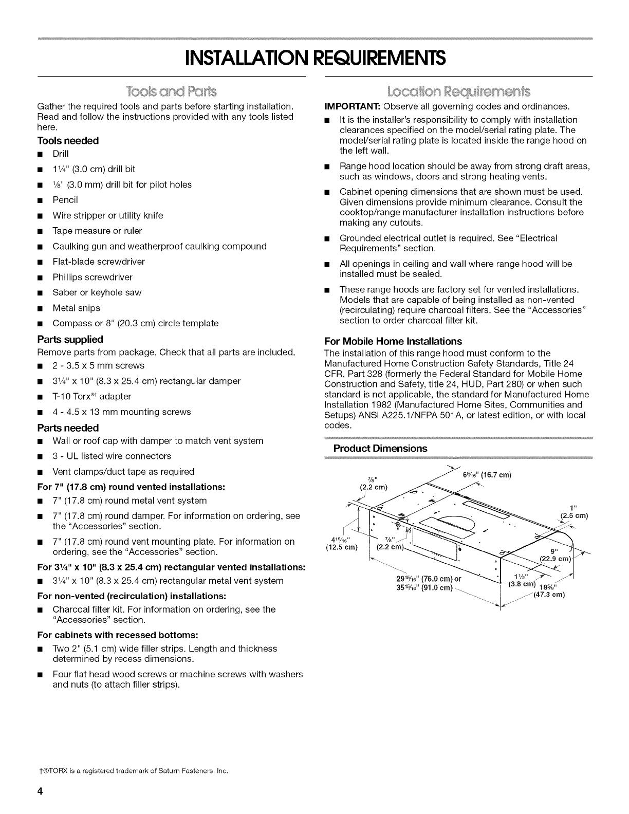
Product Dimensions
7/8"
(2.2crn)
(16.7 cm)
1 it
(2.5crn)
I
4J%6 ''
(12.5 cm)
I"®TORX is a registered trademark of Saturn Fasteners, Inc.
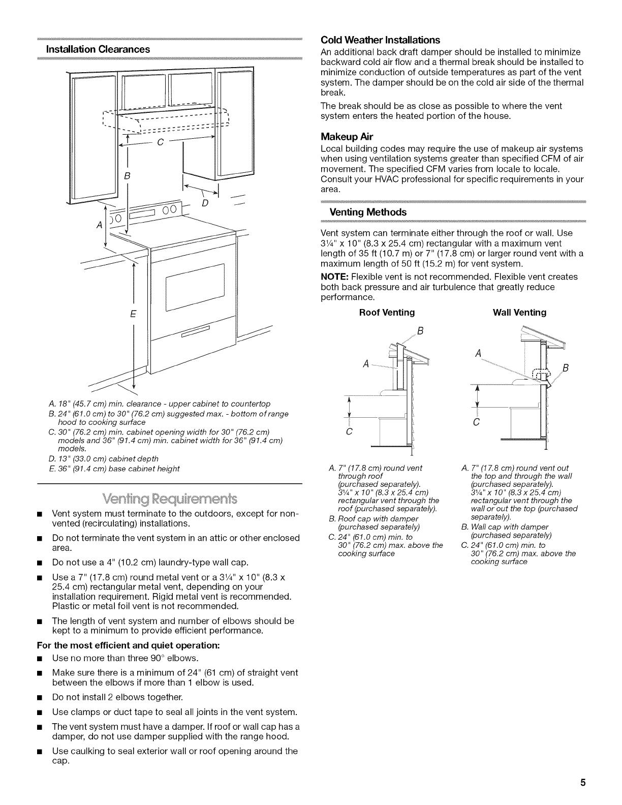
Installation Clearances
E
A. 18" (45.7 cm) min. clearance - upper cabinet to countertop
B. 24" (61.0 cm) to 30" (76.2 cm) suggested max. - bottom of range
hood to cooking surface
C. 30" (76.2 cm) min. cabinet opening width for 30" (76.2 cm)
models and 36" (91.4 cm) min. cabinet width for36" (91.4 cm)
models.
D. 13" (33.0 cm) cabinet depth
E. 36" (91.4 cm) base cabinet height
• Vent system must terminate to the outdoors, except for non-
vented (recirculating) installations.
• Do not terminate the vent system in an attic or other enclosed
area.
Do not use a 4" (10.2 cm) laundry-type wall cap.
Use a 7" (17.8 cm) round metal vent or a 3V4"x 10" (8.3 x
25.4 cm) rectangular metal vent, depending on your
installation requirement. Rigid metal vent is recommended.
Plastic or metal foil vent is not recommended.
• The length of vent system and number of elbows should be
kept to a minimum to provide efficient performance.
For the most efficient and quiet operation:
• Use no more than three 90° elbows.
• Make sure there is a minimum of 24" (61 cm) of straight vent
between the elbows if more than 1 elbow is used.
• Do not install 2 elbows together.
• Use clamps or duct tape to seal all joints in the vent system.
• The vent system must have a damper. If roof or wall cap has a
damper, do not use damper supplied with the range hood.
• Use caulking to seal exterior wall or roof opening around the
cap.
Cold Weather Installations
An additional back draft damper should be installed to minimize
backward cold air flow and athermal break should be installed to
minimize conduction of outside temperatures as part of the vent
system. The damper should be on the cold air side of the thermal
break.
The break should be as close as possible to where the vent
system enters the heated portion of the house.
Makeup Air
Local building codes may require the use of makeup air systems
when using ventilation systems greater than specified CFM of air
movement. The specified CFM varies from locale to locale.
Consult your HVAC professional for specific requirements in your
area.
Venting Methods
Vent system can terminate either through the roof or wall. Use
3V4" x 10" (8.3 x 25.4 cm) rectangular with a maximum vent
length of 35 ft (10.7 m) or 7" (17.8 cm) or larger round vent with a
maximum length of 50 ft (15.2 m) for vent system.
NOTE: Flexible vent is not recommended. Flexible vent creates
both back pressure and air turbulence that greatly reduce
performance.
Roof Venting Wall Venting
B
A.........................
..........................................£
r
C
A. 7" (17.8 cm) round vent
through roof
(purchased separately).
31/4''x 10" (8.3 x 25.4 cm)
rectangular vent through the
roof (purchased separately).
B. Roof cap with damper
(purchased separa rely)
C. 24" (61.0 cm) min. to
30" (76.2 cm) max. above the
cooking surface
A. 7" (17.8 cm) round vent out
the top and through the wall
(purchased separately).
31/4"x 10" (8.3x25.4 cm)
rectangular vent through the
wall or out the top (purchased
separately).
B. Wall cap with damper
(purchased separately)
C. 24" (61.0 cm) min. to
30" (76.2 cm) max. above the
cooking surface
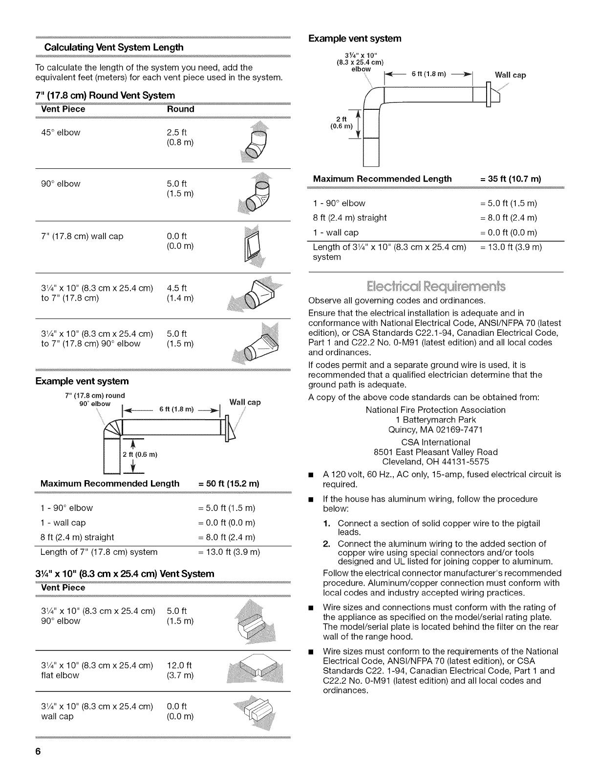
Calculating Vent System Length
To calculate the length of the system you need, add the
equivalent feet (meters) for each vent piece used in the system.
7" (17.8 cm) Round Vent System
Vent Piece Round
45° elbow 2.5 ft
(0.8m)
90° elbow 5.0 ft
(1.5m)
7" (17.8 cm) wall cap 0.0 ft
(0.0m)
Example vent system
31/4,,x 10 ,,
(8.3 x 25.4 cm)
elbow
/_ 6 ft (1.8 rn) _ Wall cap
Maximum Recommended Length = 35 ft (10.7 m)
1 - 90° elbow
8 ft (2.4 m) straight
1 - wall cap
Length of 31/4'' x 10" (8.3 cm x 25.4 cm)
system
= 5.0 ft (1.5 m)
= 8.0 ft (2.4 m)
= 0.0 ft (0.0 m)
= 13.0 ft (3.9 m)
31/4"x 10" (8.3 cm x 25.4 cm) 4.5 ft
to 7" (17.8 cm) (1.4 m)
31/4'' x 10" (8.3 cm x 25.4 cm) 5.0 ft
to 7" (17.8 cm) 90 ° elbow (1.5 m)
Example vent system
7" (17.8 cm) round
90 ° e(bow
f
2 ft (0.6 m)
R_
Wall
cap
6ft (1.8m) ----_1
I
Maximum Recommended Length = 50 ft (15.2 m)
1 - 90 ° elbow
1 - wall cap
8 ft (2.4 m) straight
Length of 7" (17.8 cm) system
= 5.0 ft (1.5 m)
= 0.0 ft (0.0 m)
= 8.0 ft (2.4 m)
= 13.0 ft (3.9 m)
31/4"x 10" (8.3 cm x 25.4 cm) Vent System
Vent Piece
31/4"x 10" (8.3 cm x 25.4 cm) 5.0 ft
90° elbow (1.5 m)
31/4"x 10" (8.3 cm x 25.4 cm) 12.0 ft
flat elbow (3.7 m)
31/4"x 10" (8.3 cm x 25.4 cm) 0.0 ft
wall cap (0.0 m)
6
Observe all governing codes and ordinances.
Ensure that the electrical installation is adequate and in
conformance with National Electrical Code, ANSI/NFPA 70 (latest
edition), or CSA Standards C22.1-94, Canadian Electrical Code,
Part 1 and C22.2 No. 0-M91 (latest edition) and all local codes
and ordinances.
If codes permit and a separate ground wire is used, it is
recommended that a qualified electrician determine that the
ground path is adequate.
A copy of the above code standards can be obtained from:
National Fire Protection Association
1 Batterymarch Park
Quincy, MA 02169-7471
CSA International
8501 East Pleasant Valley Road
Cleveland, OH 44131-5575
• A 120 volt, 60 Hz., AC only, 15-amp, fused electrical circuit is
required.
• If the house has aluminum wiring, follow the procedure
below:
1. Connect a section of solid copper wire to the pigtail
leads.
2. Connect the aluminum wiring to the added section of
copper wire using special connectors and/or tools
designed and UL listed for joining copper to aluminum.
Follow the electrical connector manufacturer's recommended
procedure. Aluminum/copper connection must conform with
local codes and industry accepted wiring practices.
Wire sizes and connections must conform with the rating of
the appliance as specified on the model/serial rating plate.
The model/serial plate is located behind the filter on the rear
wall of the range hood.
Wire sizes must conform to the requirements of the National
Electrical Code, ANSI/NFPA 70 (latest edition), or CSA
Standards C22.1-94, Canadian Electrical Code, Part 1 and
C22.2 No. 0-M91 (latest edition) and all local codes and
ordinances.

INSTALLATIONINSTRUCTIONS
NOTE: It is recommended that the vent system be installed
before hood is installed.
Before making cutouts, make sure there is proper clearance
within the ceiling or wall for exhaust vent.
1. Disconnect power.
2. Depending on your model, determine which venting method
to use: roof, wall or non-vented (recirculating).
3. Select a flat surface for assembling the range hood. Place
covering over that surface.
4. Lift the range hood and set it upside down onto covered
surface.
5. If cabinet has recessed bottom, add wood filler strips on each
side. Install screws to attach filler strips in locations shown.
Wood filler strips
(recessed cabinet
bottomsonly)
3" (7.6 cm) Wall
Determine Wiring Hole Location
Cut only one 1V4"(3.2 cm) diameter wiring access hole.
1. Determine and clearly mark a vertical centerline on the wall
and cabinet in the area the vent opening will be made.
A. Centerline
To wire through top:
1. Mark a line distance "A" from the right of the centerline on the
underside of the cabinet. Mark the point on this line that is
7/8"(2.2 cm) from back wall. Drill a 1W' (3.2 cm) diameter hole
through the cabinet at this point.
i
i
A
7/8"(2.2 cm)
from waJJ_
not cabinet
frame
Centerline
A. 8%" (21.3 cm) for30" (76.2 cm) models
11%" (28.9 cm) for36" (91.4 cm) models
To wire through wall:
1. Mark a line distance "A" from the right of the centerline on the
underside of the wall. Mark the point on this line that
is 7/8"(2.2 cm) from the underside of the cabinet. Drill a
1V4"(3.2 cm) diameter hole through the rear wall at this point.
Centerline
A. 8s/8''(21.3 cm) for30" (76.2 cm) models
11%" (28.9 cm) for36" (91.4 cm) models
Style 1 - Cut Openings for 31/4" x 10" (8.3 cm x 25.4 cm)
Rectangular Vent System
Roof Venting
To make a 41/4''x 101/2'' (10.8 cm x 26.7 cm) rectangular cutout
on the underside of cabinet top and bottom:
1. Mark lines 1/2"(1.3 cm) and 43/4"(12.1 cm) from the back wall
on the centerline of the underside of cabinet.
2. Mark lines 51¼'' (13.3 cm) to the right and left of the centerline
on the underside of cabinet.
3. Use saber or keyhole saw to cut a rectangular opening for
vent.
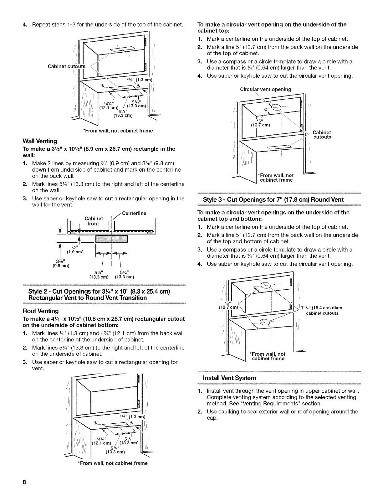
4. Repeatsteps1-3fortheundersideofthetopofthecabinet.
I
Cabinet cutouts
=11
*From wall, not cabinet frame
Wall Venting
To make a 31/2'' x 101/2'' (8.9 cm x 26.7 cm) rectangle in the
wall:
1. Make 2 lines by measuring 3/8"(0.9 cm) and 37/8"(9.8 cm)
down from underside of cabinet and mark on the centerline
on the back wall.
2. Mark lines 51¼"(13.3 cm) to the right and left of the centerline
on the wall.
3. Use saber or keyhole saw to cut a rectangular opening in the
wall for the vent.
/ Centerline
m Cabinet I/
T _r.... _4 ---"----- ..... J
+ 3/8"' I ! I
37/8" t i 1
(9.8cm) f _ /
51/4'' 51/4''
(13.3 crn) (13.3 crn)
Style 2 - Cut Openings for 3¼" x 10" (8.3 x 25.4 cm)
Rectangular Vent to Round Vent Transition
Roof Venting
To make a 41/4'' x 101/2'' (10.8 cm x 26.7 cm) rectangular cutout
on the underside of cabinet bottom:
1. Mark lines 1/2"(1.3 cm) and 43/4"(12.1 cm) from the back wall
on the centerline of the underside of cabinet.
2. Mark lines 51¼'' (13.3 cm) to the right and left of the centerline
on the underside of cabinet.
3. Use saber or keyhole saw to cut a rectangular opening for
vent.
(12.1 crn)
5V4" _1,
(13.3 crn)
*From wall, not cabinet frame
To make a circular vent opening on the underside of the
cabinet top:
1. Mark a centerline on the underside of the top of cabinet.
2. Mark a line 5" (12.7 cm) from the back wall on the underside
of the top of cabinet.
3. Use a compass or a circle template to draw a circle with a
diameter that is 1¼,,(0.64 cm) larger than the vent.
4. Use saber or keyhole saw to cut the circular vent opening.
Circular vent opening
*From wall, not
cabinet frame
Cabinet
cutouts
Style 3 - Cut Openings for 7" (17.8 cm) Round Vent
To make a circular vent openings on the underside of the
cabinet top and bottom:
1. Mark a centerline on the underside of the top of cabinet.
2. Mark a line 5" (12.7 cm) from the back wall on the underside
of the top and bottom of cabinet.
3. Use a compass or a circle template to draw a circle with a
diameter that is 1¼,,(0.64 cm) larger than the vent.
4. Use saber or keyhole saw to cut the circular vent opening.
171/4" (18.4 crn) diam.
cabinet cutouts
*From wall, not
cabinet frame
Install Vent System
1. Install vent through the vent opening in upper cabinet or wall.
Complete venting system according to the selected venting
method. See "Venting Requirements" section.
2. Use caulking to seal exterior wall or roof opening around the
cap.
8

Rc nge H@t}d
1. Remove metal grease filter. See the "Range Hood Care" 7. Remove vent knockouts depending on your installation
section, requirements.
2. Remove the 2 bottom panels.
C
A
A.Bottom panels
a. Push the panel toward the back of the range hood until
the front tabs of the panel clear the front mounting flange.
b. Pull down on the front of the panel and pull the panel
away from the rear channel. Set panels aside.
NOTE: Your model will have a 31¼'' x 10" (8.3 x 25.4 cm)
rectangular vent damper on the inside your range hood.
3. Remove the 31¼'' x 10" (8.3 x 25.4 cm) rectangular vent
damper taped on the inside your range hood.
4. Lift the range hood up under cabinet and determine final
location by centering beneath cabinet. Mark on the underside
of cabinet the location of the 4 keyhole mounting slots on the
range hood. Set range hood aside on a covered surface.
A
5.
6.
A. Keyhole slot
Use 1/8"(3 mm) drill bit and drill 4 pilot holes as shown.
A
A. Drill pilot hole
Install the 4 - 4.5 mm x 13 mm mounting screws in pilot
holes. Leave about 1/4"(6.4 cm) space between screw heads
and cabinet to slide range hood into place.
\\\\\\\\\\ i__
1/4"
(6.4 ram)
8.
A. Round vent knockout
B. Top rectangular vent knockout
C. Rear rectangular vent knockout
Round vent system installations - Remove top rectangular
and round vent knockouts.
Rectangular vent system installations - For roof
installations, remove the top rectangular vent knockout. For
wall installations, remove the rear rectangular vent knockout.
Non-vent (recirculating) installations - Do not remove any
knockouts.
Install 7" (17.8 cm) round vent mounting plate or 3W' x 10"
(8.3 x 25.4 cm) rectangular vent damper, depending on your
vent system installation. Attach to range hood with the 3.5 x
5 mm screws provided and remove tape from damper flap.
NOTE: The 7" (17.8 cm) round vent mounting plate is not
supplied. An optional 7" (17.8 cm) round damper is also
available as an accessory. For information on ordering, see
the "Accessories" section.
...........A
!
C
D
E
A. 7" (17.8 cm) Round damper (see "Accessories" section)
B. 3.5 x 5 mm screws
C. 7" (17.8 cm) round vent mounting plate (see
"Accessories" section)
D. Round vent knockout
E.Rectangular vent knockout
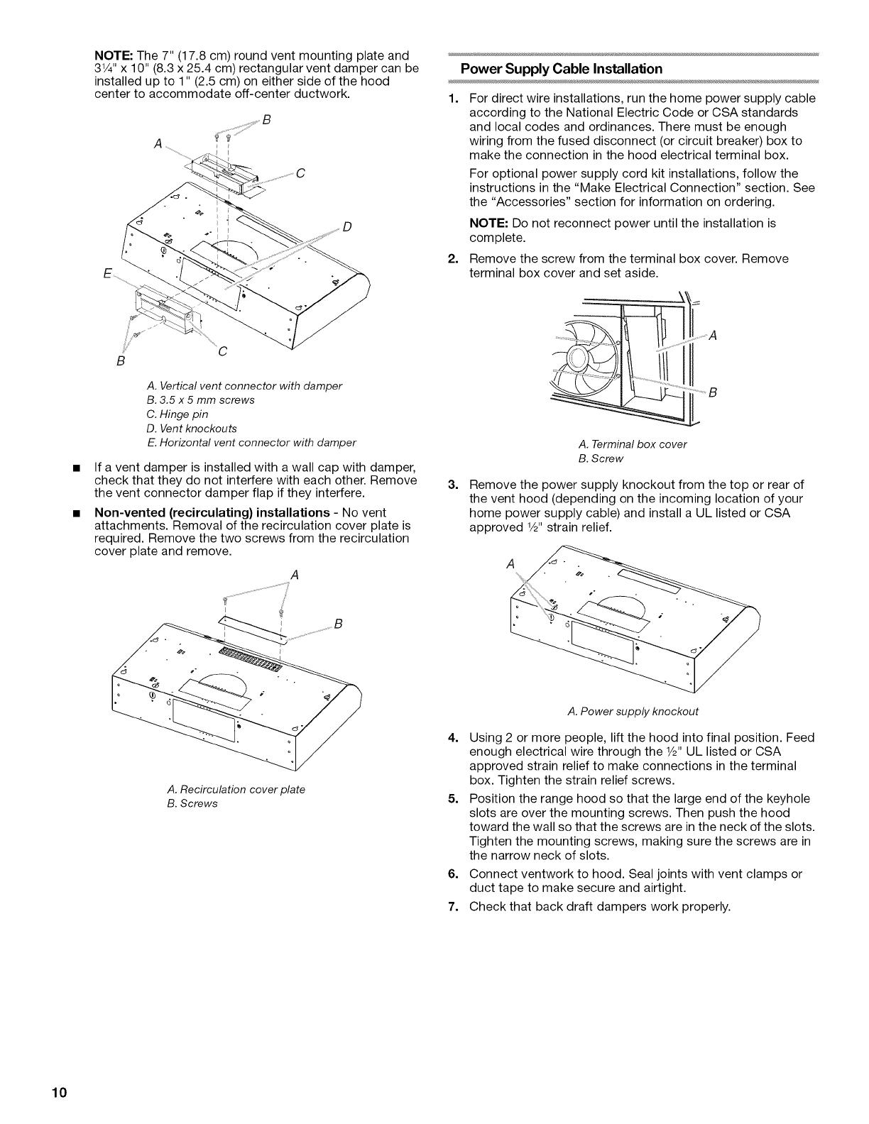
NOTE: The 7" (17.8 cm) round vent mounting plate and
31/4'' x 10" (8.3 x 25.4 cm) rectangular vent damper can be
installed up to 1" (2.5 cm) on either side of the hood
center to accommodate off-center ductwork.
¸¸¸%¸¸
_C
B
A. Vertical vent connector with damper
B. 3.5 x 5 mm screws
C. Hinge pin
D. Vent knockouts
E. Horizontal vent connector with damper
If a vent damper is installed with a wall cap with damper,
check that they do not interfere with each other. Remove
the vent connector damper flap if they interfere.
Non-vented (recirculating) installations - No vent
attachments. Removal of the recirculation cover plate is
required. Remove the two screws from the recirculation
cover plate and remove.
Power Supply Cable Installation
1. For direct wire installations, run the home power supply cable
according to the National Electric Code or CSA standards
and local codes and ordinances. There must be enough
wiring from the fused disconnect (or circuit breaker) box to
make the connection in the hood electrical terminal box.
For optional power supply cord kit installations, follow the
instructions in the "Make Electrical Connection" section. See
the "Accessories" section for information on ordering.
NOTE: Do not reconnect power until the installation is
complete.
2. Remove the screw from the terminal box cover. Remove
terminal box cover and set aside.
A. Terminal box cover
B. Screw
3=
Remove the power supply knockout from the top or rear of
the vent hood (depending on the incoming location of your
home power supply cable) and install a UL listed or CSA
approved 1/2'strain relief.
A
A. Recirculation cover plate
B. Screws
A. Power supply knockout
4. Using 2 or more people, lift the hood into final position. Feed
enough electrical wire through the 1/2"UL listed or CSA
approved strain relief to make connections in the terminal
box. Tighten the strain relief screws.
5. Position the range hood so that the large end of the keyhole
slots are over the mounting screws. Then push the hood
toward the wall so that the screws are in the neck of the slots.
Tighten the mounting screws, making sure the screws are in
the narrow neck of slots.
6. Connect ventwork to hood. Seal joints with vent clamps or
duct tape to make secure and airtight.
7. Check that back draft dampers work properly.
10
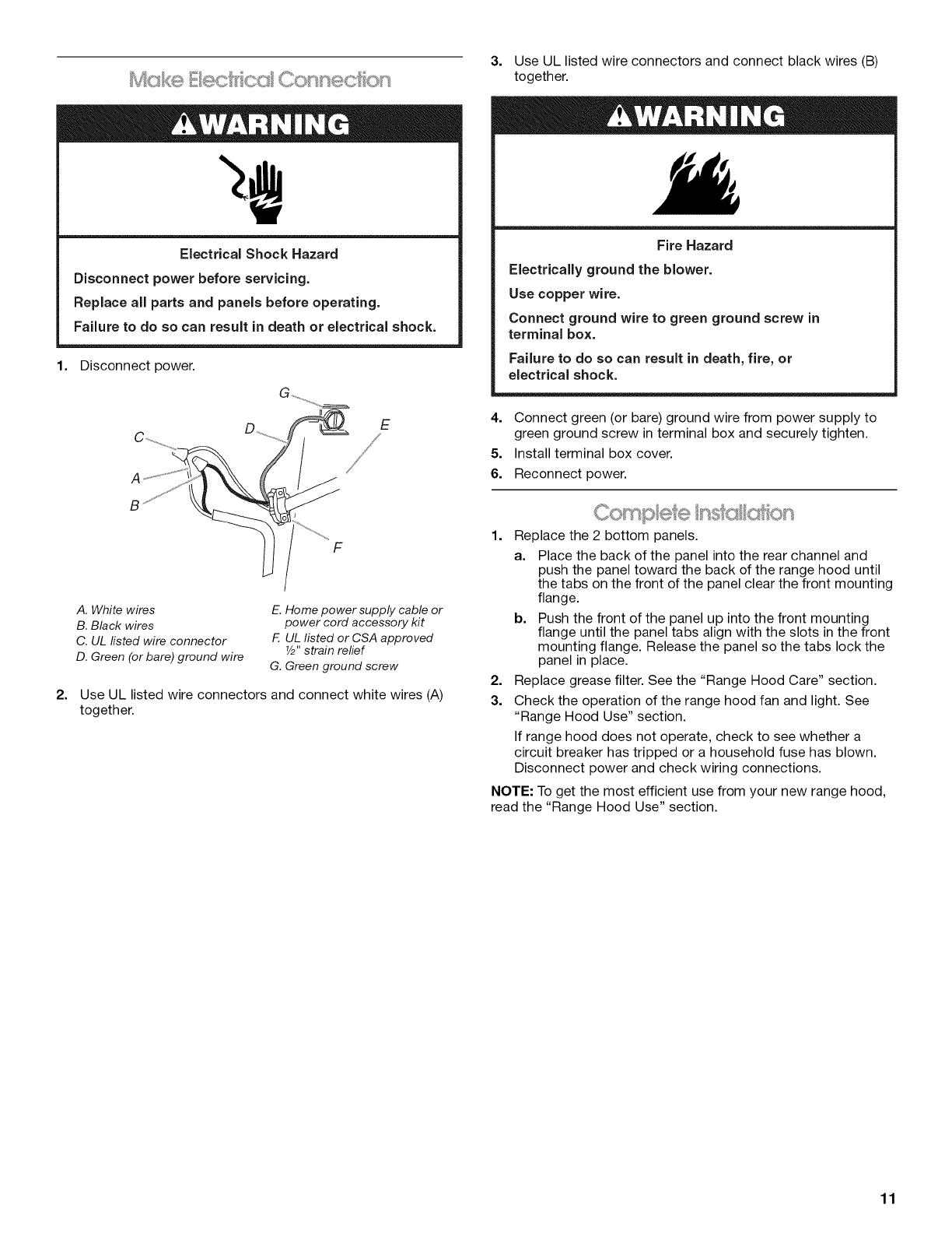
Electrical Shock Hazard
Disconnect power before servicing.
Replace all parts and panels before operating.
Failure to do so can result in death or electrical shock.
1. Disconnect power.
3. Use UL listed wire connectors and connect black wires (B)
together.
Fire Hazard
Electrically ground the blower.
Use copper wire.
Connect ground wire to green ground screw in
terminal box.
Failure to do so can result in death, fire, or
electrical shock.
2=
F
E
A. White wires
B. Black wires
C. UL fisted wire connector
D. Green (or bare) ground wire
E. Home power supply cable or
power cord accessory kit
F. UL listed or CSA approved
Y2"strain relief
G. Green ground screw
Use UL listed wire connectors and connect white wires (A)
together.
4. Connect green (or bare) ground wire from power supply to
green ground screw in terminal box and securely tighten.
5. Install terminal box cover.
6. Reconnect power.
1. Replace the 2 bottom panels.
a. Place the back of the panel into the rear channel and
push the panel toward the back of the range hood until
the tabs on the front of the panel clear the front mounting
flange.
b. Push the front of the panel up into the front mounting
flange until the panel tabs align with the slots in the front
mounting flange. Release the panel so the tabs lock the
panel in place.
2. Replace grease filter. See the "Range Hood Care" section.
3. Check the operation of the range hood fan and light. See
"Range Hood Use" section.
If range hood does not operate, check to see whether a
circuit breaker has tripped or a household fuse has blown.
Disconnect power and check wiring connections.
NOTE: To get the most efficient use from your new range hood,
read the "Range Hood Use" section.
11

RANGE HOOD USE
The range hood is designed to remove smoke, cooking vapors
and odors from the cooktop area. For best results, start the hood
before cooking and allow it to operate several minutes after the
cooking is complete to clear all smoke and odors from the
kitchen.
The hood controls are located on the front panel of the range
hood.
A
C iii
B
A. Halogen lights
B. Grease filter
C. Filter retainer
Rc ag® * ood C,o
A B C D
ONIOFF ONIOFF Med High
oo©o )
A. On/Off light button
B. Blower off and speed minimum button
C. Blower speed medium button
D. Blower speed maximum button
Operating the light
The On/Off light button controls both lights. Press once for On
and again for Off.
Operating the blower
The BLOWER SPEED buttons turn the blower on and control the
blower speed and sound level for quiet operation. The speed can
be changed anytime during fan operation by pressing the desired
blower speed button.
Press the BLOWER OFF button a second time to turn the blower
off.
RANGE HOOD CARE
IMPORTANT: Clean the hood and grease filters frequently
according to the following instructions. Replace grease filter
before operating hood.
Exterior Surfaces:
IMPORTANT: Do not use soap-filled scouring pads, abrasive
cleaners, Cooktop Polishing Creme, steel wool, gritty washcloths
or paper towels.
To avoid damage to the stainless steel, do not use cleaners that
contain chlorine.
Cleaning Method:
• Rub in direction of grain to avoid scratching or damaging the
surface.
For stainless steal models, Stainless Steel Cleaner and Polish
Part Number 31462A (not included): See "Assistance or
Service" section to order.
• Liquid detergent or all-purpose cleaner:
Rinse with clean water and dry with soft, lint-free cloth.
• Glass cleaner to remove fingerprints.
Metal or Charcoal Filter
3.
C
A. Screw
B. Grease filter retainer
C. Grease filter
For vented installations: Wash metal filters as needed in a
dishwasher or hot detergent solution.
For non-vented (recirculating) installations: The charcoal
filter is not washable. It should last up to 6 months with
normal use. Replace the metal filters with charcoal filters. For
information on ordering, see the "Accessories" section.
Dispose of old charcoal filter.
12
To Replace the Filter:
1. To reinstall the filter, the single slot opening on the long edge
of the filter is to be toward the front of the range hood. Place
the back edge of the filter into the channel at the rear of the
range hood.
2. Pull the filter retainer toward the front of the range hood and
push the front of the filter up into place.
3. Release the filter retainer. It will spring back into place to
secure the filter.
4. Replace the screw into the filter retainer.
Replacing a Halogen Lamp
Turn off the range hood and allow the halogen lamp to cool. To
avoid damage or decreasing the life of the new lamp, do not
touch lamp with bare fingers. Replace lamp, using tissue or
wearing cotton gloves to handle lamp.
If new lights do not operate, make sure the lamps are inserted
correctly before calling service.
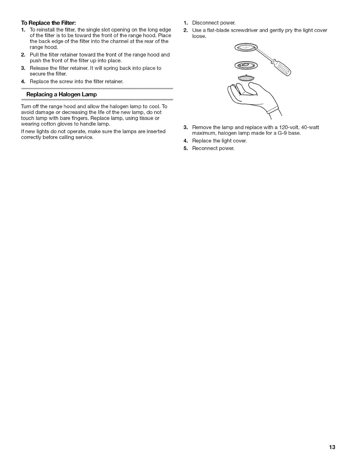
1=
2.
Disconnect power.
Use a flat-blade screwdriver and gently pry the light cover
loose.
3. Remove the lamp and replace with a 120-volt, 40-watt
maximum, halogen lamp made for a G-9 base.
4. Replace the light cover.
5. Reconnect power.
13
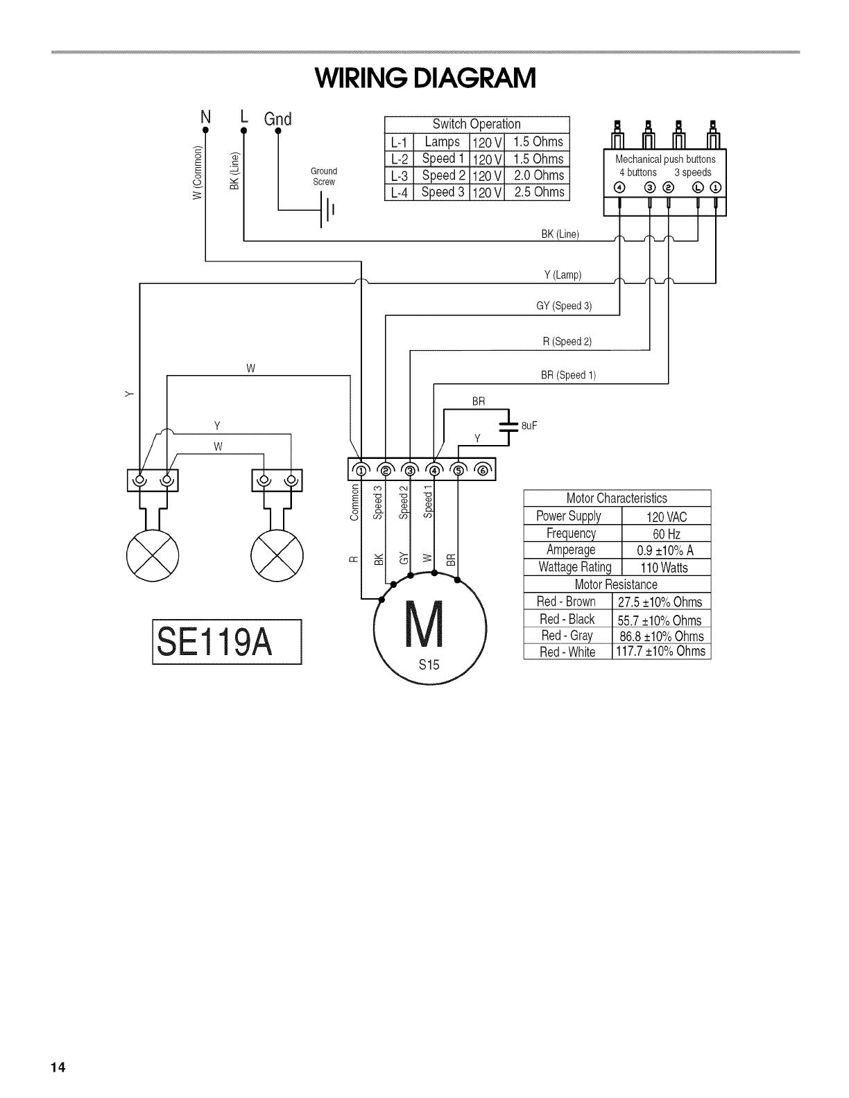
WIRING DIAGRAM
N
8
Ground
Screw
Gnd
W
Y
SwitchOperation
L-1 Lamps 120V 1.5Ohms
L-2 Speed1 120V 1.5Ohms
L-3 Speed2 120V 2.0Ohms
L-4 Speed3 120V 2.5Ohms
SE119A
i
BK (Line)
Y(Lamp)
GY (Speed3)
Mechanicalpushbuttons I
(_ butto(_ _)3 sp_)ds(_)
I " TII
S15
R (Speed2)
BR(Speed1)
MotorCharacteristics
PowerSupply 120VAC
Frequency 60Hz
Amperage 0.9+10%A
WattageRating 110Watts
MotorResistance
Red-Brown 27.5+10%Ohms
Red-Black 55.7+10%Ohms
Red-Gray 86.8+10%Ohms
Red-White 117.7+10%Ohms
14

ASSISTANCEOR SERVICE
When calling for assistance or service, please know the purchase
date and the complete model and serial number of your
appliance. This information will help us to better respond to your
request.
If you need replacement parts
If you need to order replacement parts, we recommend that you
use only factory specified parts. Factory specified parts will fit
right and work right because they are made with the same
precision used to build every new appliance. To locate factory
specified replacement parts in your area, call us or your nearest
designated service center.
Call the Whirlpool Customer eXperience Center
toll free: 1-800-253-1301.
Our consultants provide assistance with:
• Features and specifications on our full line of appliances.
• Installation information.
• Use and maintenance procedures.
• Accessory and repair parts sales.
• Specialized customer assistance (Spanish speaking, hearing
impaired, limited vision, etc.).
• Referrals to local dealers, repair parts distributors and service
companies. Whirlpool designated service technicians are
trained to fulfill the product warranty and provide after-
warranty service, anywhere in the United States.
To locate the Whirlpool designated service company in your
area, you can also look in your telephone directory Yellow
Pages.
For further assistance
If you need further assistance, you can write to Whirlpool
Corporation with any questions or concerns at:
Whirlpool Brand Home Appliances
Customer eXperience Center
553 Benson Road
Benton Harbor, MI 49022-2692
CalltheWhirlpoolCanada LP Customer experienceCentretoll
free:1-800-807-8777.
Our consultants provide assistance with:
• Features and specifications on our full line of appliances.
• Use and maintenance procedures.
• Accessory and repair parts sales.
• Referrals to local dealers, repair parts distributors, and
service companies. Whirlpool Canada LP designated service
technicians are trained to fulfill the product warranty and
provide after-warranty service, anywhere in Canada.
For further assistance
If you need further assistance, you can write to Whirlpool
Canada LP with any questions or concerns at:
Customer eXperience Centre
Whirlpool Canada LP
200 - 6750 Century Ave.
Mississauga, Ontario L5N 0B7
Please include a daytime phone number in your correspondence.
Stainless Steel Cleaner and Polish
Order Part Number 31462A
Charcoal Filter Kit
Order Part Number W10386873
Power Cord Kit
Order Part Number W10355452
7" (17.8 cm) Round Damper
Order Part Number W10355451
7" (17.8 cm) Round Vent Mounting Plate
Order Part Number W10388168
Please include a daytime phone number in your correspondence.
15

WHIRLPOOLCORPORATIONMAJOR APPLIANCEWARRANTY
LIMITED WARRANTY
For one year from the date of purchase, when this major appliance is operated and maintained according to instructions attached to or
furnished with the product, Whirlpool Corporation or Whirlpool Canada LP (hereafter "Whirlpool") will pay for Factory Specified Parts
and repair labor to correct defects in materials or workmanship. Service must be provided by a Whirlpool designated service company.
This limited warranty is valid only in the United States or Canada and applies only when the major appliance is used in the country in
which it was purchased. Outside the 50 United States and Canada, this limited warranty does not apply. Proof of original purchase date
is required to obtain service under this limited warranty.
ITEMS EXCLUDED FROM WARRANTY
This limited warranty does not cover:
1. Service calls to correct the installation of your major appliance, to instruct you on how to use your major appliance, to replace or
repair house fuses, or to correct house wiring or plumbing.
2. Service calls to repair or replace appliance light bulbs, air filters or water filters. Consumable parts are excluded from warranty
coverage.
3. Repairs when your major appliance is used for other than normal, single-family household use or when it is used in a manner that is
contrary to published user or operator instructions and/or installation instructions.
4. Damage resulting from accident, alteration, misuse, abuse, fire, flood, acts of God, improper installation, installation not in
accordance with electrical or plumbing codes, or use of consumables or cleaning products not approved by Whirlpool.
5. Cosmetic damage, including scratches, dents, chips or other damage to the finish of your major appliance, unless such damage
results from defects in materials or workmanship and is reported to Whirlpool within 30 days from the date of purchase.
6. Any food loss due to refrigerator or freezer product failures.
7. Costs associated with the removal from your home of your major appliance for repairs. This major appliance is designed to be
repaired in the home and only in-home service is covered by this warranty.
8. Repairs to parts or systems resulting from unauthorized modifications made to the appliance.
9. Expenses for travel and transportation for product service if your major appliance is located in a remote area where service by an
authorized Whirlpool servicer is not available.
10. The removal and reinstallation of your major appliance if it is installed in an inaccessible location or is not installed in accordance
with published installation instructions.
11. Major appliances with original model/serial numbers that have been removed, altered or cannot be easily determined. This warranty
is void if the factory applied serial number has been altered or removed from your major appliance.
The cost of repair or replacement under these excluded circumstances shall be borne by the customer.
DISCLAIMER OF IMPLIED WARRANTIES; LIMITATION OF REMEDIES
CUSTOMER'S SOLE AND EXCLUSIVE REMEDY UNDER THIS LIMITED WARRANTY SHALL BE PRODUCT REPAIR AS PROVIDED
HEREIN. IMPLIED WARRANTIES, INCLUDING WARRANTIES OF MERCHANTABILITY OR FITNESS FOR A PARTICULAR PURPOSE,
ARE LIMITED TO ONE YEAR OR THE SHORTEST PERIOD ALLOWED BY LAW. WHIRLPOOL SHALL NOT BE LIABLE FOR
INCIDENTAL OR CONSEQUENTIAL DAMAGES. SOME STATES AND PROVINCES DO NOT ALLOW THE EXCLUSION OR LIMITATION
OF INCIDENTAL OR CONSEQUENTIAL DAMAGES, OR LIMITATIONS ON THE DURATION OF IMPLIED WARRANTIES OF
MERCHANTABILITY OR FITNESS, SO THESE EXCLUSIONS OR LIMITATIONS MAY NOT APPLY TO YOU. THIS WARRANTY GIVES
YOU SPECIFIC LEGAL RIGHTS, AND YOU MAY ALSO HAVE OTHER RIGHTS WHICH VARY FROM STATE TO STATE OR PROVINCE
TO PROVINCE.
If outside the 50 United States and Canada, contact your authorized Whirlpool dealer to determine if another warranty applies.
If you need service, first see the "Troubleshooting" section of the Use & Care Guide. After checking "Troubleshooting," you may find
additional help by checking the "Assistance or Service" section or by calling Whirlpool. In the U.S.A., call 1-800-253-1301. In Canada,
call 1-800-807-6777. 6/12
Keep this book and your sales slip together for future
reference. You must provide proof of purchase or installation
date for in-warranty service.
Write down the following information about your major appliance
to better help you obtain assistance or service if you ever need it.
You will need to know your complete model number and serial
number. You can find this information on the model and serial
number label located on the product.
Dealer name
Address
Phone number
Model number
Serial number
Purchase date
16
SECURITEDELA HOTTEDECUISINIERE
Votre securite et celle des autres est tres importante.
Nous donnons de nombreux messages de s_curit_ importants dans ce manuel et sur votre appareil m_nager. Assurez-vous de
toujours lire tousles messages de s_curit_ et de vous y conformer.
Voici le symbole d'alerte de s_curit&
Ce symbole d'alerte de s_curit_ vous signale les dangers potentiels de d_c_s et de blessures graves & vous
et & d'autres.
Tousles messages de s_curit_ suivront le symbole d'alerte de s_curit_ et le mot "DANGER" ou
"AVERTISSEMENT". Ces mots signifient •
Risque possible de d_cbs ou de blessure grave si vous ne
suivez pas imm_diatement les instructions.
Risque possible de d_cbs ou de blessure grave si vous
ne suivez pas les instructions.
Tousles messages de s_curit_ vous diront quel est le danger potentiel et vous disent comment r_duire le risque de blessure et
ce qui peut se produire en cas de non-respect des instructions.
17
llVlPORTANTES iNSTRUCTiONS DE Sl CURITl
AVERTISSEMENT : POUR REDUIRE LE RISQUE
D'INCENDIE, CHOC ELECTRIQUE OU DOMMAGES
CORPORELS, RESPECTER LES INSTRUCTIONS
SUIVANTES :
[] Utiliser cet appareil uniquement dans les applications
envisag6es par le fabricant. Pour toute question, contacter
le fabricant.
[] Avant d'entreprendre un travail d'entretien ou de nettoyage,
interrompre I'alimentation de la hotte au niveau du tableau
de disjoncteurs, et verrouiller le tableau de disjoncteurs
pour emp6cher tout r6tablissement accidentel de
I'alimentation du circuit. Lorsqu'il n'est pas possible de
verrouiller le tableau de disjoncteurs, placer sur le tableau
de disjoncteurs une @iquette d'avertissement pro6minente
interdisant le r@ablissement de I'alimentation.
[] Tout travail d'installation ou c&blage 61ectrique doit @re
r6alis6 par une personne qualifi6e, darts le respect des
prescriptions de tousles codes et normes applicables, y
compris les codes du b&timent et de protection contre les
incendies.
[] Ne pas faire fonctionner un ventilateur dont le cordon ou la
fiche est endommag6(e). Jeter le ventilateur ou le retourner
& un centre de service agr66 pour examen et/ou r6paration.
[] Une source d'air de d6bit suffisant est n6cessaire pour le
fonctionnement correct de tout appareil &gaz (combustion
et 6vacuation des gaz & combustion par la chemin6e), pour
qu'il n'y ait pas de reflux des gaz de combustion. Respecter
les directives du fabricant de 1'6quipement de chauffage et
les prescriptions des normes de s6curit6 - comme celles
publi6es par la National Fire Protection Association (NFPA)
et I'American Society for Heating, Refrigeration and Air
Conditioning Engineers (ASHRAE), et les prescriptions des
autorit6s r6glementaires locales.
[] Lors d'op@ations de d6coupage et de per£:age dans un mur
ou un plafond, veiller & ne pas endommager les c&blages
61ectriques ou canalisations qui peuvent s'y trouver.
[] Les ventilateurs d'6vacuation doivent toujours d6charger
I'air &I'ext@ieur.
MISE EN GARDE : Cet appareil est con£:u uniquement
pour la ventilation g6n@ale. Ne pas I'utiliser pour I'extraction
de mati_res ou vapeurs dangereuses ou explosives.
MISE EN GARDE : Pour minimiser le risque d'incendie
et 6vacuer ad6quatement les gaz, veiller & acheminer I'air
aspir6 par un conduit jusqu'b, I'ext@ieur - ne pas d6charger
I'air aspir6 dans un espace vide du b&timent comme une
cavit6 murale, un plafond, un grenier, un vide sanitaire ou
un garage.
AVERTISSEMENT : POUR REDUIRE LE RISQUE
D'INCENDIE, UTILISER UNIQUEMENT DES CONDUITS
METALLIQUES.
AVERTISSEMENT : POUR MINIMISER LE RISQUE
D'UN FEU DE GRAISSE SUR LA CUISINIF:RE :
[] Ne jamais laisser un 616ment de surface fonctionner &
puissance de chauffage maximale sans surveillance. Un
renversement/d6bordement de mati@e graisseuse pourrait
provoquer une inflammation et la g6n@ation de fum6e.
Utiliser une puissance de chauffage moyenne ou basse
pour le chauffage d'huile.
[] Veiller & toujours faire fonctionner le ventilateur de la hotte
Iors de la cuisson avec une puissance de chauffage 61ev6e
ou Iors de la cuisson d'un mets &flamber (& savoir cr6pes
Suzette, cerise jubil6e, steak au poivre flamb6).
[] Nettoyer fr6quemment les ventilateurs d'extraction. Veiller &
ne pas laisser la graisse s'accumuler sur les surfaces du
ventilateur ou des filtres.
[] Utiliser toujours un ustensile de taille appropri6e. Utiliser
toujours un ustensile adapt6 & la taille de 1'616ment
chauffant.
AVERTISSEMENT : POUR REDUIRE LE RISQUE DE
DOMMAGES CORPORELS APRF:S LE DECLENCHEMENT
D'UN FEU DE GRAISSE SUR LA CUISINI_:RE, APPLIQUER
LES RECOMMANDATIONS SUIVANTES :a
[] Placer sur le r6cipient un couvercle bien ajust6,, une t61e &
biscuits ou un plateau m6tallique POUR ETOUFFER LES
FLAMMES, puis @eindre le brOleur. VEILLER ,&.¢:VITER
LES BRULURES. Si les flammes ne s'@eignent pas
imm6diatement, CVACUER LA PIECE ET APPELER LES
POMPIERS.
[] NE JAMAIS PRENDRE EN MAIN UN R¢:CIPIENT
ENFLAMMI 2 - vous risquez de vous brOler.
[] NE PAS UTILISER D'EAU, ni un torchon humide - ceci
pourrait provoquer une explosion de vapeur brOlante.
[] Utiliser un extincteur SEULEMENT si :
- II s'agit d'un extincteur de classe ABC, dont on connait le
fonctionnement.
- II s'agit d'un petit feu encore limit6 &I'endroit oQ il s'est
d6clar&
- Les pompiers ont 6t6 contact6s.
- II est possible de garder le dos orient6 vers une sortie
pendant I'op@ation de lutte contre le feu.
aRecommandations tir6es des conseils de s6curit6 en cas
d'incendie de cuisine publi6s par la NFPA.
[] AVERTISSEMENT : Pour r6duire le risque d'incendie
ou de choc 61ectrique, ne pas utiliser ce ventilateur avec un
quelconque dispositif de r6glage de la vitesse &semi-
conducteurs.
LIRE ET CONSERVER CES INSTRUCTIONS
18
EXIGENCESD'INSTALLATION
Rassembler les outils et pieces necessaires avant d'entreprendre
I'installation. Lire et observer les instructions fournies avec
chacun des outils de la liste ci-dessous.
Outils n_cessaires
• Perceuse
• Foret de lY4" (3 cm)
• Foret de V8"(3 mm) pour avant-trous
• Crayon
• Pince a denuder ou couteau utilitaire
• M_tre-ruban ou r_gle
• Pistolet & calfeutrage et compose de calfeutrage resistant
aux intemperies
• Tournevis a lame plate
• Tournevis Phillips
• Scie sauteuse ou scie a guichet
• Cisaille de ferblantier
• Compas ou gabarit de diam_tre 8" (20,3 cm)
Pi_ces fournies
Retirer los pieces de I'emballage. Verifier que toutes los pieces
sont presentes.
• 2visde3,5x5mm
• Module clapet rectangulaire de 3V4"x 10" (8,3 x 25,4 cm)
• Raccord d'adaptation T-10 Torx _t
• 4 vis de montage de 4,5 x 13 mm
Pi_ces n_cessaires
• Douche de decharge murale ou & travers le toit avec clapet
correspondant au systeme d'evacuation
• 3 connecteurs de ills homologu6s UL
• Brides de conduit/ruban adhesif pour tuyauteries (solon le
besoin)
Installations avec d_charge a I'ext_rieur et conduits ronds de
7" (17,8 cm) :
• Systeme de conduit d'evacuation metallique rond de 7"
(17,8 cm)
• Clapet anti-reflux rond de 7" (17,8 cm). Pour commander des
pieces, voir la section "Accessoires".
• Plaque de montage de conduit rond de 7" (17,8 cm). Pour
commander des pieces, voir la section "Accessoires".
Installations avec d_charge a I'ext_rieur et conduits
rectangulaires de 3V4"x 10" (8,3 x 25,4 cm) :
• Systeme d'evacuation rectangulaire metallique de 31/4"x 10"
(8,3 x 25,4 cm)
Installations sans d_charge a I'ext_rieur (recyclage) :
• Ensemble de filtre a charbon. Pour commander des pieces,
voir la section "Accessoires".
Pour placards avec cavit_ au fond :
• Deux tringles d'appui de largeur 2" (5,1 cm). Longueur et
epaisseur solon los dimensions de I'encastrement.
• Quatre vis & bois a t_te plate ou vis &metaux avec rondelles
et ecrous, pour la fixation des tringles d'appui.
I"®TORX est une marque d6pos6e de Saturn Fasteners, Inc.
IMPORTANT : Observer les dispositions de tous les codes et
r_glements en vigueur.
• C'est a I'installateur qu'incombe la responsabilite de
respecter les distances de separation exigees, specifiees sur
la plaque signaletique de I'appareil. La plaque signaletique
est situ_e a I'interieur de la hotte, sur la paroi de gauche.
• Installer la hotte de cuisiniere a distance de toute zone
exposee a des courants d'air, comme fenatres, portes et
bouches de chauffage a fort debit.
• Respecter les dimensions indiquees pour les ouvertures
decouper dans les placards. Ces dimensions tiennent
compte des valeurs minimales des degagements de
separation. Avant d'effectuer des decoupages, consulter les
instructions d'installation fournies par le fabricant de la table
de cuisson/cuisiniere.
• On doit disposer d'une prise de courant electrique reliee a la
terre. Voir la section "Specifications electriques".
• Assurer I'etancheite au niveau de chaque ouverture
decoupee dans le plafond ou lemur pour I'installation de la
hotte de cuisiniere.
Cos hottes de cuisiniere ont ete configurees &I'usine pour
une installation avec decharge & I'exterieur. Los modeles
pouvant _tre installes dans une configuration sans decharge
I'exterieur (recyclage) necessitent des filtres & charbon. Voir
la section "Accessoires" pour commander un ensemble de
filtre a charbon.
Installation dans une r_sidence mobile
L'installation de cette hotte doit satisfaire aux exigences de la
norme Manufactured Home Construction Safety Standards, Titre
24 CFR, partie 328 (anciennement Federal Standard for Mobile
Home Construction and Safety, titre 24, HUD, partie 280); Iorsque
cette norme n'est pas applicable, I'installation doit satisfaire aux
criteres de la plus recente edition de la norme Manufactured
Home Installation 1982 (Manufactured Home Sites, Communities
and Setups) ANSI A225.1/NFPA 501A, ou des codes Iocaux.
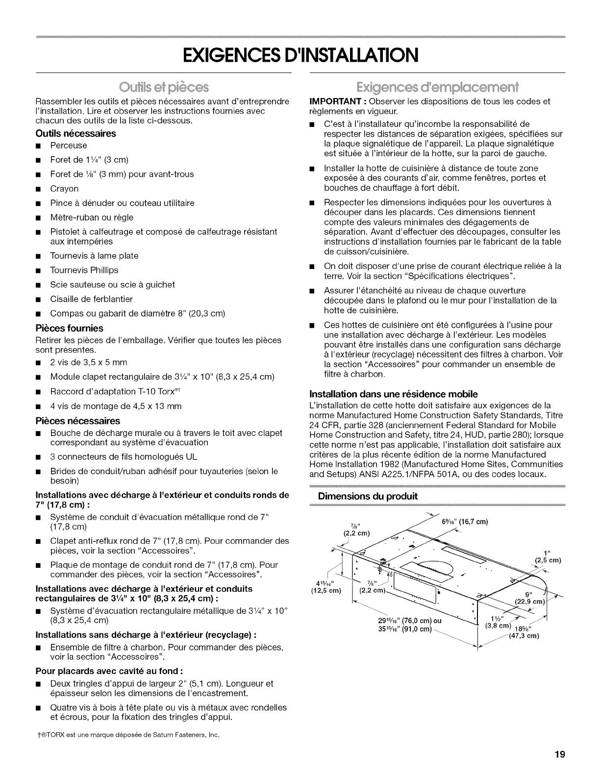
Dimensions du produit
(16,7cm)
J.
(2,5cm)
19

Distances de d_gagement & respecter
E
A. D_gagement min. de 18" (45, 7 cm) entre le placard sup_rieur et
le plan de travail
B. 24" (61,0 cm) _ 30" (76,2 cm) : distance maximale sugg_r_e du
bas de la hotte _ la surface de cuisson
C. 30" (76,2 cm) de largeur de placard min. pour les modeles de
30" (76,2 cm) et 36" (91,4 cm) de largeur min. de placard pour
les modeles de 36" (91,4 cm).
D. Profondeur de placard 13" (33 cm)
E. Hauteur de placard du bas 36" (91,4 cm)
Le systeme d'evacuation doit decharger I'air a I'exterieur,
excepte pour les installations sans decharge a I'exterieur
(recyclage).
Ne pas terminer le circuit d'evacuation dans un grenier ou
dans un autre espace clos.
Ne pas utiliser une bouche de decharge murale de
4" (10,2 cm) normalement utilisee pour un equipement de
buanderie.
Utiliser un conduit metallique rond de 7" (17,8 cm) ou un
conduit metallique rectangulaire de 3V4"x 10" (8,3 x 25,4 cm),
selon les besoins de I'installation. Un conduit en metal rigide
est recommand& Ne pas utiliser de conduit de plastique ou
en aluminium.
La Iongueur du systeme d'evacuation et le nombre de coudes
doit _tre reduit au minimum pour des performances optimales.
Pour un fonctionnement efficace et silencieux :
Ne pas utiliser plus de trois coudes a 90°.
Veiller & ce qu'il y ait une section droite de conduit d'un
minimum de 24" (61 cm) entre les raccords coudes, si on doit
en utiliser plus d'un.
Ne pas installer 2 coudes successifs.
Au niveau de chaque jointure du circuit d'evacuation, assurer
I'etanch6it6 avec les brides de serrage ou du ruban adhesif &
tuyauteries.
Le circuit d'evacuation doit comporter un clapet anti-reflux. Si
la bouche de decharge murale ou par le toit comporte un
clapet, ne pas utiliser le clapet fourni avec la hotte de
cuisiniere.
A I'aide d'un produit de calfeutrage, assurer I'etanch6it6
autour de la bouche de decharge & I'exterieur (&travers le
mur ou le toit).
Installations dans les r_gions au climat froid
On doit installer un clapet anti-retour supplementaire a I'arriere
pour minimiser le reflux d'air froid et incorporer un el6ment
d'isolation thermique pour minimiser la conduction de chaleur
par I'intermediaire du conduit d'evacuation, de I'interieur de la
maison & I'exterieur. Le clapet anti-retour doit _tre place du c6te
air froid de la resistance thermique.
Uel6ment d'isolation thermique doit _tre aussi proche que
possible de I'endroit oQ le circuit d'evacuation s'introduit dans la
partie chauffee de la maison.
Air d'appoint
Les codes du b&timent local peuvent exiger I'emploi d'un
systeme d'appoint d'air Iors de I'emploi d'un ventilateur
d'extraction dont la capacite d'aspiration est superieure & un
debit (pieds cubes par minute) specifi& Le debit specifi6 en pieds
cubes par minute varie d'une juridiction &I'autre. Consulter un
professionnel des installations de chauffage ventilation/
climatisation au sujet des exigences specifiques applicables
dans la juridiction locale.
M_thodes d'6vacuation
La sortie & I'exterieur du circuit d'evacuation peut se faire
travers le toit ou & travers un mur. Utiliser des conduits
rectangulaires de 3V4" x 10" (8,3 x 25,4 cm) avec une Iongueur
maximale de 35 pi (10,7 m) ou des conduits rond de 7" (17,8 cm)
de diametre ou plus avec une Iongueur maximale de 50 pi
(15,2 m) pour le systeme d'evacuation.
REMARQUE • On deconseille I'emploi d'un conduit flexible. Un
conduit flexible peut causer une retro-pression et des
turbulences de I'air, ce qui reduirait considerablement la
performance.
20
/