Kenmore POWER MISER 6 153.336466 User manual
- Category
- Water heaters & boilers
- Type
- User manual

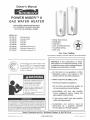
Owner's Manual
POWER MISERTM 6
GAS WATER HEATER
FOR POTABLE WATER HEATING ONLY.
NOT SUITABLE FOR SPACE HEATING,
NOT FOR USE IN MOBILE HOMES.
MODEL NO.
153,336162
153.336262
153,336362
153,336466
153,336566
153,336762
153,336862
153.336962
30 Gallon Short
40 GaHon Short
30 Gallon
40 Gallon
50 Gallon
30 Gallon Propane (L.R)
40 Gallon Propane (L.R)
50 Gallon Propane (L.P,)
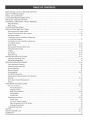
* Safety mnstructions
* mnstaHation
* Operation
* Care and Maintenance
* Troubleshooting
* Parts List
For Your Safety
AN ODORANT ISADDED TO THE GAS USED BYTHIS WATER HEATER.
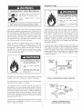
C3 Technology s*Gas Water Heaters meet
the new ANSI Z21.10.1 standard that deals
with the accidental or unintended ignition
of flammable vapors, such as those
emitted by gasoline.
Read and understand instruction
manual and safety messages
before instaNing, operating or
servicing this water heater.
Failure to follow instructions and
safety messages could result in
death or serious injury'.
Instruction manual must remain
with water heater.
Si no puede leer o entender el ingles y necesita el manual instructivo
y/o etiquetas en espaSol puede obtenerlos Ilamando al
1=800=821=2017. NO TRATE DE INSTALAR O OPERAR ESTE
CALENTADOR DEAGUAsi no entiende lainfom_aci6n en las etiquetas
o en el manual instructivo. No hacer caso de esta advertencia podria
resultar en laMU ERTE O GRAVES LESIONES CORPORALES.
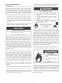
WARNING: if the information in these
instructions is not followed exactly, a fire
or explosion may result causing property
damage, personal injury or death.
--Do not store or use gasoline or other
flammable vapors and liquids in the
vicinity of this or any other appliance.
-- WHAT TO DO iF YOU SMELL GAS:
• Do not try to light any appliance.
o Do not touch any emectricam switch; do
not use any phone in your buimding.
,, mmmediatemy caml your gas suppmier
from a neighbor's phone. Fommow the
gas eupplier'e instructions,
,, mfyou cannot reach your gas suppmier,
cammthe fire department.
--Installation and service must be
performed by a qualified installer,
service agency orthe gas supplier.
Sears, Roebuck and Co., Hoffman Estates, _L 60179 U.S.A
PRINTED IN THE U.S.A 0705 V',_nC_,'v,seat'S,CO_rn PART NO 184231-001

Your safety and the safety of others is extremely important in the installation, use and servicing of this water heater.
Many safetyoreLated messages and instructions have been provided in this manual and on your own water heater to warn you and
others of a potential injury hazard. Read and obey all safety messages and instructions throughout this manuaL, mtis very
important that the meaning of each safety message is understood by you and others who instalm, use or service this water heater.
This is the safety amert symbol, ff is used to alert you
to potential personal injury hazards. Obey aH safety
messages that follow this symbol to avoid possible
injury or death.
DANGER indicates an imminently
hazardous situation which, if not avoided,
could result in death or injury.
WARNmNG indicates a potentially hazardous
situation which, if not avoided, could result
in death or injury.
CAUTmON indicates a potentially hazardous
situation which, if not avoided, may result
in minor or moderate injury.
CAUTLON used without the safety aJert
symbo{ indicates a potentially hazardous
situation which, if not avoided, could result
in property damage.
AH safety messages will generally tell you about the type of hazard, what can happen if you do not follow the safety message and
how to avoid the risk of injury.
IMPORTANT DEF_NIT_ONS
Gas Supplier: The natural gas or propane utility or service who supplies gas for utilization by the gas burning
appliances within this application. The gas supplier typically has responsibility for the inspection and code approval of
gas piping up to and including the natural gas meter or propane storage tank of a building. Many gas suppliers also
offer service and inspection of appliances within the building.
© Sears, Roebuck and Co,

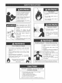
Readandunderstandinstruction
manualandsafetymessages
beforeinstalling,operatingor
servicingthiswaterheater
Failuretofollowinstructionsand
safetymessagescouldresultin
deathorseriousinjury,
Instructionmanualmustremain
withwaterheater
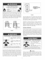
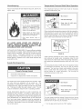
Fire Hazard
mtinued protection against
riskof fire:
,Do ot install water heater on
carl: .tted floor
,Do ot operate water heater if
flood damaged.
Water temperature over 125°F
(52°0) can cause severe burns
instantly resulting in severe injury
or death_
Children, the elderly, and the
physically or mentally disabled
are at highest r[skfor scald injury.
Feel water before bathing or
showering
Temperature limiting valves are
available.
Read instruction manual for safe
temperature setting.
Fire or Explosion Hazard
Do not store or use gasoline or other flammable
vapors and liquids in the vicinity of this or any other
appliance.
Avoid all ignition sources if you smell LP gas_
, Do not expose water heater control to excessive gas
pressure.
, Use only gas shown on rating plate
, Maintain required clearances to combustibles_
, Keep ignition sources away from faucets after
,, extended period of nen-use.
J
Read instruction manual before
installing, using or sewucmg
water heater.
Explosion Hazard
o Overheated water can cause
water tankexplosion,
-Properly sized temperature
and pressure relief valve must
be installed in opening
provided.
Breathing Hazard - Carbon Monoxide (}as
• Install vent system in accordance with
codes,
• Do not operate water heater it flood
damaged.
• High altitude or[flee must be installed for
operation above 7,700 feet (2,347 m)
, Do not operate [f soot buildup.
• Do not obstruct water heater air intake
with insulating jacket.
• Do not place chemical vapor emitting
products near water heater.
• Gas and carbon monoxide detectors
are available
Breathing carbon monoxide can cause brain damage or
death, Always read and understand instruction manual
improper installation and use may result
in property damage.
, Do not operate water heater if flood damaged
o Inspect and replace anode.
o Install in location with drainage,
- Fill tank with water before operation.
• Be alert for thermal expansion
Refer to instruction manual for installation and service.


ThankYouforpurchasingaKenmorewaterheater.Properly
installedandmaintained,itshouldgiveyouyearsoftrouble
freeservice.Ifyoushoulddecidethatyouwantthenewwater
heaterprofessionallyinstalledbySearscall1-800-4+MY-HOME®.
Theywillarrangeforprompt,qualityinstallationbySears
authorizedcontractors.
AbbreviationsFoundInThisInstructionManual:
CSA- CanadianStandardsAssociation
ANSI-AmericanNationalStandardsInstitute
NFPA-NationalFireProtectionAssociation
ASME-AmericanSocietyofMechanicalEngineers
GAMA- Gas Appliance Manufacturers Association
This gas-fired water heater is design certified by CSA
INTERNATIONAL under American National Standard/CSA
Standard for Gas Water Heaters ANSI Z21.10.1 • CSA 4.1
(current edition).
Read the "Safety Precautions" section, page 3 of this manual
first and then the entire manual carefully+ If you don't follow
the safety rules, the water heater will not operate properly. It
could cause DEATH, SERIOUS BODILY INJURY AND/OR
PROPERTY DAMAGE.
This manual contains instructions for the installation,
operation, and maintenance of the gas-fired water heater. It
also contains warnings through out the manual that you must
read and be aware of+ All warnings and all instructions are
essential to the proper operation of the water heater and
your safety. Since we cannot put everything on the first few
pages, READ THE ENTIRE MANUAL BEFORE ATTEMPTING
TO INSTALL OR OPERATE THE WATER HEATER.
The installation must conform with these instructions and
the local code authority having jurisdiction. In the absence of
local codes, installations shall comply with the following:
In the United States: The National Fuel Gas Code ANSI
Z223.1/NFPA 54+ This publication is available from the
Canadian Standards Association, 8501 East Pleasant Valley
Rd, Cleveland Ohio 44131, or The Nationa! Fire Protection
Association, 1 Batterymarch Park, Quincy, MA 02269.
If after reading this manual you have any questions or do not
understand any portion of the instructions, call the Sears
Service Center.
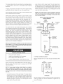
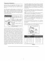
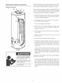
Carefully plan the place where you are going to put the water
heater. Correct combustion, vent action, and vent pipe
installation are very important in preventing death from
possible carbon monoxide poisoning and fires. See
figure 1.
Examine the location to ensure the water heater complies
with the Facts to Consider About the Location section in this
manual.
For California installation this water heater must be braced,
anchored, or strapped to avoid falling or moving during an
earthquake. See instructions for correct installation
procedures. Instructions may be obtained from your local
dealer, wholesaler, public utilities or California Office of the
State Architect, 400 P Street, Sacramento, CA 95814.
Massachusetts Code requires this water heater to be
installed in accordance with Massachusetts 248-CMR 2.00:
State Plumbing Code and 248-CMR 5.00.
Complies with SCAQMD rule #1121 and districts having
equivalent NOx requirements.
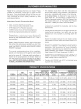
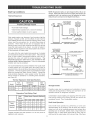
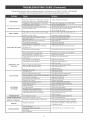
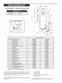
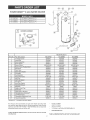
RECOVERY MiNiMUM DIMENSIONS
TANK TYPE iNPUT RATE GALS VENT PiPE DIAMETER iN iNCHES (rein}
MODEL CAPACITY OF RATE PER HOUR iNCHES iNCHES HEIGHT TO
NUMBER N GALS (LTRS GAS (Btu/hr) @ 9G°F RISl (ram) (ram) JACKET TOP
153.336162 30 (114) NATURAL 32,000 30.6 3" (76) or 4" (!02) 18 1/2" (470) 43 3/4" (1,!11)
153.336262 40 (! 51) NATURAL 35,500 35.4 3" (76) or 4" (102) 20" (508) 47 1/4" (1,200)
153.336362 30 (114) NATURAL 35,500 34.9 3" (76) 16" (406) 57 1/2" (I ,461 )
153.336466 40 (! 51) NATURAL 35,500 35.4 3" (76) 18 1/2" (470) 55 1/2" (1,41 O)
153.336566 50 (! 89) NATURAL 35,500 35.4 3" (76) 20" (508) 56 1/2" (! ,435)
153.336762 30 (114) PROPANE 35,500 34.9 3" (76) 16" (406) 57 1/2" (! ,461 )
153.336862 40 (!51) PROPANE 35,500 35.4 3" (76) 18 1/2" (470) 55 1/2" (! ,410)
153.336962 50 (! 89) PROPANE 35,500 35.4 3" (76) 20" (508) 56 1/2" (! ,435)

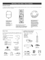
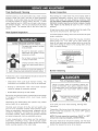
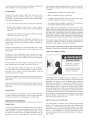
Materials Needed
To simplify the installation Sears has available the installation parts shown below. You may or may not need al! of these materials,
depending on your type of installation.
EXPANSION TANKS FOR
THERMAL EXPANSION
CONDITIONS AVAILABLE
IN 2 GALLONS
(7=5 LITERS) AND
5 GALLONS (18.8 LITERS)
CAPACITY NROUGN
LOCAL SEARS STORE OR
SERVICE CENTER.
_'"'............i!1I_
_,_ I
_'_il I_
WATER HEATER INSTALLATION KIT WITH
FLEXIBLE CONNECTORS FOR 8/4"
(19.05 ram) OR 1/2" (12.7 ram) THREADED OR
COPPER PLUMBING AND FLEXIBLE WATER
HEATER GAS CONNECTOR W_TH FITTINGS.
DRAIN PANS AVAILABLE iN 20"
(508 ram) DIAMETER FOR
WATER HEATERS HAVING A
DIAMETER 18" (457 ram) OR
LESS, 24" (510ram) DIAMETER
FOR WATER HEATERS HAVING
A DIAMETER 22" (559 ram) OR
LESS AND AVAILABLE iN 28"
(711 ram) DIAMETER FOR
WATER HEATERS HAVING A
DIAMETER 25" (550 ram) OR
LESS.
Basic Too_s
You may or may not need all these tools, depending on your
type of installation, These tools can be purchased at your local
Sears Store,
Pipe Wrenches (2) 14" (356 ram)
Screwdriver
Tin Snips
6' (1.82 m) Tape or Fo_ding Ru_er
Garden Hose
DriH
Pipe Dope or Teflon Tape DRILL
SLOT-HEAD SCREWDRIVER
PHILLIPS SCREWDRIVER
TIN SNIPS
ROLL OF TEFLON
TAPE (USE ONLY ON
WATER CONNECTIONS)
PIPE DOPE
(SQUEEZE TUBE)
USE FOR WATER AND GAS
CONNECTIONS
GARDEN HOSE 5 FOOT TAPE PIPE WRENCH
Additionam Too_s Needed
When Sweat So_dering
Tubing Cutters or Hacksaw
Propane Tank
Soft Solder
Solder Fmux
Emery C_oth
Wire Brushes
TUBING CUTTER
PROPANE
TORCH
HACKSAW
ROLL OF
EMERYCLOTH
8/4" (19 ram) WiRE BRUSH
ROLL OF LEAD-FREE
1/2" (13 ram) WIRE BRUSH SOFT SOLDER
SOLDER
FLUX

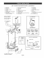
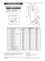
GET TO KNOW YOUR WATER HEATER oGAS MODELS
A Vent Pipe J Drip Leg (Sediment Trap) S F[ueBaff[e
B Draft Hood K BnnerDoor T Thermostat
C Anode L Outer door U Drain Valve
D Hot Water Outlet M Union V Pilot and Main Burner
E Outlet N BnmetWater Shut-off Valve W Flue
F Flexible Water Connections O Cold Water mnlet X Drain Pan
G GasSupply P hmet Dip Tube Y Thermostat Shiemd (optional)
H ManuamGasShut-offVa[ve Q Temperature-Pressure Relief Valve Z Piezo[gaiter
m Ground Joint Union R Rating Plate AA AirlntakeScreen
* tNSTALL JN ACCORDANCE
WiTH LOCAL CODES.
* DRmP LEG AS REQUIRED
BY LOCAL CODES.
TO VENT TERMiNATiON
ON ROOF
LJ
w
V
fR
U
YJ THERMOSTAT
COVER
{OPTIONAL)
(T) THERMOSTAT
GAS CONTROL KNOB
E
WATER TE_,_PERATURE
(ADJUSTING DIAL)
"OFF .... PILOT .... ON"
POSITUON POSITION POSITION
TOP ViEW
(V) PILOT & MAIN BURNER
BURNER TUBE
PULOTTUBmNG
/
THERMOCOUPLE
TCO
UGNmTER ROD

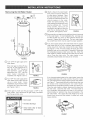
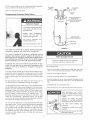
Removing the O_d Water Heater (_
F_GURE2.
Q Turn "OFF" the gas supply to the
water heater.
If the main gas line Shut-off valve
serving all gas appliances is
used, also shut "OFF" the gas at
each appliance. Leave al! gas
appliances shut "OFF" until the
water heater installation is
completed, see Figures 2 and 3.
RGURE 3.
Q Turn "OFF" the water supply to the
water heater at the water shut off
valve or water meter. Some
installations require that the water
be turned off to the entire house,
see Figures 2 and 4.
FIGURE4.
Check again to make sure the supply is "OFF" to the
Q . gas
water heater. Then disconnect the gas supply connection
from the gas control valve.
Burn hazard
* Hotwater discharge.
o Keep hands clear of drain
valve discharge,
®
®
Attach a hose to the water heater
drain valve and put the other end
in a floor drain or outdoors. Open
the water heater drain valve. Open
a nearby hot water faucet which wil!
relieve pressure in the water
heater and speed draining. The
water passing out of the drain valve
may be extremely hot. To avoid
being scalded, make sure al!
connections are tight and that the
water flow is directed away from
any person, see Figures 2 and 5.
FIGURE 5.
Disconnect the vent pipe from the draft hood where it connects
to the water heater. In most installations the vent pipe can
be lifted off after any screw or other attached devices are
removed. Dispose of the draft hood. The new water heater
has a draft hood which must be used for proper operation.
If you have copper piping to the water heater, the two copper
water pipes can be cut with a hacksaw approximately four
inches away from where they connect to the water heater,
see Figure 6. This wil! avoid cutting off pipes too short.
Additional cuts can be made later if necessary. Disconnect
the temperature-pressure relief valve drain line. When the
water heater is drained, disconnect the hose from the drain
valve. Close the drain valve. The water heater is now
completely disconnected and ready to be removed.
FmGURE6.
If you have galvanized pipes to the water heater, loosen the
two galvanized pipes with a pipe wrench at the union in each
line. Also disconnect the piping remaining to the water heater,
see Figure 7. These pieces should be saved since they may
be needed when reconnecting the new water heater.
Disconnect the temperature-pressure relief valve drain line.
When the water heater is drained, disconnect the hose from
the drain valve. Close the drain valve. The water heater is
now completely disconnected and ready to be removed.
Mineral buildup or sediment may have accumulated in the
old water heater. This causes the water heater to be much
heavier than normal and this residue, if spilled out, could
cause staining.
FmGURE7.

Facts to Consider About
the Location
Carefully choose an indoor location for the new water heater,
because the placement is a very important consideration for
the safety of the occupants in the building and for the most
economical use of the appliance. This water heater is not for
use in manufactured (mobile) homes or outdoor installation.
Whether replacing an old water heater or putting the water heater
in a new location, the following critical points must be observed:
Select a location indoors as close as practical to the gas
vent or chimney to which the water heater vent is going to be
connected, and as centralized with the water piping system
as possible.
* Selected location must provide adequate clearances for
servicing and proper operation of the water heater.
Property Damage Hazard
, All water heaters eventually leak
, Do not install without adequate drainage.
Installation of the water heater must be accomplished in such a
manner that if the tank or any connections should leak, the flow
will not cause damage to the structure. For this reason, it is not
advisable to install the water heater in an attic or upper floor.
When such locations cannot be avoided, a suitable drain pan
should be installed under the water heater. Drain pans are
available at your local Sears or hardware store. Such a drain
pan must have a minimum length and width of at bast 2 inches
(51 mm) greater that the water heater dimensions and must be
piped to an adequate drain. The pan must not restrict
combustion air flow.
Water heater life depends upon water quality, water pressure
and the environment in which the water heater is installed.
Water heaters are sometimes installed in locations where
leakage may result in property damage, even with the use of a
drain pan piped to a drain. However, unanticipated damage
can be reduced or prevented by a leak detector or water shut-
off device used in conjunction with a piped drain pan. These
devices are available from some plumbing supply wholesalers
and retailers, and detect and react to leakage in various ways:
• Sensors mounted in the drain pan that trigger an alarm or turn
off the incoming water to the water heater when leakage is
detected.
* Sensors mounted in the drain pan that turn off the water supply
to the entire home when water is detected in the drain pan.
* Water supply shut-off devices that activate based on the water
pressure differential between the cold water and hot water
pipes connected to the water heater.
• Devices that will turn off the gas supply to a gas water heater
while at the same time shutting off its water supply.
Fire or Explosion Hazard
Do not store or use gasoline or other flammable
vapors and liquids in the vicinity of this or any other
appliance_
• Avoid all ignition sources if you smell LP gas.
, Do not expose water heater control to excessive gas
pressure.
, Use only gas shown on rating plate.
, Maintain required clearances to combustibles.
• Keep ignition sources away from faucets after
,, extended period of non-use.
Read instruction manual before
installing, using or servicing
water heater
INSTALLATIONS IN AREAS WHERE FLAMMABLE LIQUIDS
(VAPORS) ARE LIKELY TO BE PRESENT OR STORED
(GARAGES, STORAGE AND UTILITY AREAS, ETC.):
Flammable liquids (such as gasoline, solvents, propane [LP or
butane, etc.] and other substances such as adhesives, etc.)
emit flammable vapors which can be ignited by a gas water
heater's pilot light or main burner. The resulting flashback and
fire can cause death or serious burns to anyone in the area.
Even though this water heater is a flammable vapors ignition
resistant water heater and is designed to reduce the chances
of flammable vapors being ignited, gasoline and other
flammable substances should never be stored or used in the
same vicinity or area containing a gas water heater or other
open flame or spark producing appliance.
Also, the water heater must be located and/or protected so it is
not subject to physical damage by a moving vehicle.
Fire Hazard
For continued protection against
risk of fire:
,Do not install water heater on
carpeted floor.
Do not operate water heater if
flood damaged.
This water heater must not be installed directly on carpeting.
Carpeting must be protected by metal or wood panel beneath
the appliance extending beyond the full width and depth of the
appliance by at least 3 inches (76.2 ram) in any direction, or if
the appliance is installed in an alcove or closet, the entire floor
must be covered by the panel. Failure to heed this warning may
result in a fire hazard.

Fire or Explosion Hazard
Read instruction manual before installing,
using or servicing water heater
° improper use may result in fire or
explosion,
• Maintain required clearances to
combustibles.
Minimum clearances be_,,veen the water heater and combustible
construction are 0 inch at the sides and rear,
4 inches (102 ram) at the front, and 6 inches (153 ram) from the
vent pipe, see Figure 8. Clearance from the top of the jacket is 12
inches (305 ram) on most models. Note that a lesser dimension
may be allowed on some models, refer to the labe! attached
adjacent to the gas control valve on the water heater.
TOP V_EW TOP VIEW
OF CLOSET OF CLOSET
WITHOUT DOOR WiTH DOOR
O" BVIIN.
O" M|N.
FIGURE&
Breathing Hazard = Carbon Monoxide Gas
Install water heater in accordance
with the instruction manual and
NFPA 54.
To avoid injury, combustion and
venNation air must be taken from
outdoors
Do not place chemical vapor
emitting products near water
heater.
Breathing carbon monoxide can cause brain damage or
death, Always read and understand instruction manual,
A gas water heater cannot operate properly without the correct
amount of air for combustion, see Figure 9. Do not install in a
confined area such as a closet, unless you provide air as shown
in the Locating The New Water Heater section. Never obstruct
the flow of ventilation air. If you have any doubts or questions at
all, call your gas supplien Failure to provide the proper amount
of combustion air can result in a fire or explosion and cause
death, serious bodily injury, or property damage.
,L12 '' MAX. {30 era}
7
VEN'RLATION
FRONT vmEw
OF DOOR
AmRDUCT
RGURE&
If this water heater will be used in beauty shops, barber shops,
cleaning establishments, or self=service laundries with dry
cleaning equipment, it is imperative that the water heater or
water heaters be installed so that combustion and ventilation
air be taken directly from outdoors (direct vent).
Propellants of aerosol sprays and volatile compounds,
(cleaners, chlorine based chemicals, refrigerants, etc.) in
addition to being highly flammable in many cases, will also
change to corrosive hydrochloric acid when exposed to the
combustion products of the water heater. The results can be
hazardous, and also cause product failure.
Insulation B_ankets
Insulation blankets available to the general public for external
use on gas water heaters are not necessary with Kenmore
products. The purpose of an insulation blanket is to reduce the
standby heat loss encountered with storage tank heaters. Your
Kenmore water heater meets or exceeds the National Appliance
Energy Conservation Act standards with respect to insulation
and standby loss requirements, making an insulation blanket
unnecessary.
Breathing Hazard - Carbon Monoxide Gas
. Do not obstruct water heater air
intake with insulating blanket.
. Gas and carbon monoxide detectors
are available
Install water heater in accordance
with the instruction manual,
Breathing carbon monoxide can cause brain damage or
death Always read and understand instruction manual,
Should you choose to apply an insulation blanket to this heater,
you should follow these instructions (See Figure 1 for
identification of components mentioned below). Failure to follow
these instructions can restrict the air flow required for proper
combustion, potentially resulting in fire, asphyxiation, serious
personal injury or death.
10

Donotapplyinsulationtothetopofthewaterheater,asthis
willinterferewithsafeoperationofthedrafthood.
Donotcovertheouterdoor,thermostatortemperature&
pressurereliefvalve.
Donotallowinsulationtocomewithin2"(50_8mm)ofthe
floortopreventblockageofcombustionairflowtotheburner.
DonotcovertheinstructionmanualKeepitonthesideof
thewaterheaterornearbyforfuturereference.
DoobtainnewwarningandinstructionlabelsfromSears
forplacementontheblanketdirectlyovertheexistinglabels.
Doinspecttheinsulationblanketfrequentlytomakecertain
itdoesnotsag,therebyobstructingcombustionairflow.
commencewithin12inches(30cm)ofthetopandone
commencingwithin12inches(30cm)ofthebottomofthe
enclosures.
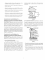
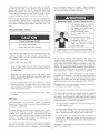
Combustion Air and Ventilation for
Appmiances Located in Unconfined Spaces
UNCONFINED SPACE is space whose volume is not less than
50 cubic feet per 1,000 Btu per hour (4.8 m3 per kW) of the
aggregate input rating of all appliances installed in that space_
Rooms communicating directly with the space in which the
appliances are installed, through openings not furnished with
doors, are considered a part of the unconfined space.
In unconfined spaces in buildings, infiltration may be adequate
to provide air for combustion, ventilation and dilution of flue
gases. However, in buildings of tight construction (for example,
weather stripping, heavily insulated, caulked, vapor barrier, etc.),
additional air may need to be provided using the methods
described in Combustion Air and Ventilation for Appfiances
Located in Confined Spaces.
Combustion Air and Ventimation for
Appliances Located in Confined Spaces
CONFINED SPACE is a space whose volume is less than
50 cubic feet per 1,000 Btu per hour (4.8 m_ per kW) of the
aggregate input rating of all appliances installed in that space.
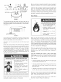
A. ALL AIR FROM INSmDE BUmLDgNGS:
(See Figure 9 on page 9 and Figure 10 below)
The confined space shall be provided with two permanent
openings communicating directly with an additional room(s)
of sufficient volume so that the combined volume of all spaces
meets the criteria for an unconfined space. The total input of
al! gas utilization equipment installed in the combined space
shall be considered in making this determination. Each
opening shall have a minimum free area of one square inch
per 1,000 Btu per hour (22 cm2/kW) of the total input rating of al!
gas utilization equipment in the confined space, but not less
than 100 square inches (645 cm2). One opening shal!
FIGURE1&
B. ALL AIR FROM OUTDOORS: (See Figures 9, 11,12 and 13)
The confined space shall be provided with two permanent
openings, one commencing within 12 inches (30 cm) of the
top and one commencing within 12 inches (30 cm) from the
bottom of the enclosure. The openings shall communicate
directly, or by ducts, with the outdoors or spaces (craw! or attic)
that freely communicate with the outdoors.
VENT&ATUON LOUVERS
END OF ATTIC_
ALT. INLETAIR VENTULATUON LOUVERS
FmGURE11,
When directly communicating with the outdoors, each opening
shall have a minimum free area of 1 square inch per 4,000 Btu
per hour (5.5 cm_/kW) of total input rating of all equipment in the
enclosure, see Figure 12.
When communicating with the outdoors through vertical
ducts, each opening shall have a minimum free area of
1 square inch per 4,000 BTU per hour (5.5 cm_/kW) of total
input rating of all equipment in the enclosure, see
Figure 12.
11

FIGURE12.
Whencommunicatingwiththeoutdoorsthroughhorizontal
ducts,eachopeningshallhaveaminimumfreeareaof1
squareinchper2,000BTUperhour(11cm2/kW)oftotal
inputratingof all equipmentin theenclosure,see
Figure13.
Whenductsareused,theyshallbeofthesamecross-
sectionalareaasthefreeareaoftheopeningstowhich
theyconnect.Theminimumshortsidedimensionof
rectangularair ductsshallnotbelessthan3inches
(76.2ram),seeFigure13.
OUTLET AURDUCT
Water Piping
Water temperature over 125°F
(52°0) can cause severe burns
instantly resulting in severe injury
or death.
Children, elderly, and the
physically or mentally disabled
are at highest risk for scald injury.
Feel water before bathing or
showering
Temperature limiting valves are
available.
Read instruction manual for safe
temperature setting
HOTTER WATER CAN SCALD:
VVater heaters are intended to produce hot water. Water heated
to a temperature which will satisfy space heating, clothes
washing, dish washing, cleaning and other sanitizing needs
can scald and permanently injure you upon contact. Some
people are more likely to be permanently injured by hot water
than others. These include the elderly, children, the infirm, or
physically/mentally handicapped. Ifanyone using hotwaterin
your home fits into one of these groups or if there is a local
code or state law requiring a certain temperature water at the
hot water tap, then you must take special precautions. In
addition to using the lowest possible temperature setting that
satisfies your hot water needs, a means such as a *mixing
valve, shall be used at the hot water taps used by these people
or at the water heater. Mixing valves are available at plumbing
supply or hardware stores, see Figure 14 below. Valves for
reducing point of use temperature by mixing cold and hot water
are also available. Follow manufacturer's instructions for
installation of the valves. Before changing the factory setting
on the thermostat, read the Temperature Regulation section in
this manual.
HNLET AiR DUCT
FIGURE 13.
Louvers and Grilles: In calculating free area, consideration
shall be given to the blocking effect of louvers, grilles or
screens protecting openings. Screens used shall not be
smaller than 1/4 inch (6.4 mm) mesh. If the free area through
a design of louver or grille is known, it should be used in
calculating the size opening required to provide the free
area specified. If the design and free area is not known, it
may be assumed that wood louvers will be 20-25 percent
free area and metal louvers and grilles will have 60-75
percent free area. Louvers and grilles shall be fixed in the
open position or interlocked with the equipment so that they
are opened automatically during equipment operation.
Special Conditions Created by Mechanical Exhausting or
Fireplaces: operation of exhaust fans, ventilation systems,
clothes dryers or fireplaces may create conditions requiring
special attention to avoid unsatisfactory operation of installed
gas utilization equipment.
*MIXING NOT _JATER
VALVE OUTLET ON
WATERNEATER
WATER HEATER
FIGURE14.
Toxic Chemical Hazard
* Do not connect to non-potable water system.
12

Thiswaterheatershallnotbeconnectedtoanyheatingsystems
orcomponent(s)usedwitha non-potablewaterheating
appliance.
Allpipingcomponentsconnectedtothisunitforspaceheating
applicationsshallbesuitableforusewithpotablewater.
Lookatthetopofthewaterheater.Thecoldwaterinletis
marked'COLD".Puttwoorthreeturnsofteflontapearound
thethreadedendofthethreaded-to-sweatcouplingand
aroundbothendsofthe3/4"NPTthreadednipple.Using
flexibleconnectors,connectthecoldwaterpipetothecold
waterinletofthewaterheater.
Toxicchemicals,suchasthoseusedforboilertreatmentshall
notbeintroducedintothissystem.
Watersupplysystemsmay,becauseofsucheventsashigh
linepressure,frequentcut-offsortheeffectsofwaterhammer
amongothers,haveinstalleddevicessuchaspressure
reducingvalves,checkvalves,backflowpreventers,etc.to
controlthesetypesofproblems.Whenthesedevicesarenot
equippedwithaninternalby-pass,andnoothermeasuresare
taken,thedevicescausethewatersystemtobeclosed.As
waterisheated,itexpands(thermalexpansion)andclosed
systemsdonotallowfortheexpansionofheatedwater.
Thewaterwithinthewaterheatertankexpandsasitisheated
andincreasesthepressureofthewatersystem.Iftherelieving
pointofthewaterheater'stemperature-pressurereliefvalveis
reached,thevalvewillrelievetheexcesspressure.The
temperature-pressurereliefvalveis notintendedfor the
constantreliefofthermalexpansion.Thisisanunacceptable
conditionandmustbecorrected.Itisrecommendedthatany
devicesinstalledwhichcouldcreateaclosedsystemhavea
by-passand/orthesystemhaveanexpansiontanktorelieve
thepressurebuiltbythermalexpansioninthewatersystem.
RefertotheTheTma! Expansion section under Troubleshooting
Guide or contact local plumbing authority or local Sears Service
Center on how to control this situation.
NOTE: To protect against untimely corrosion of hot and cold
water fittings, it is strongly recommended that dioelectric
unions or couplings be installed on this water heater when
connected to copper pipe.
Property Damage Hazard
oAvoid water heater damage.
• Install thermal expansion tank if necessary.
, Do not apply heat to cold water inlet
, Contact qualified installer or Sears Service Center.
NOTE: This water heater is super insulated to minimize
heat loss from the tank. Further reduction in heat loss
can be accomplished by insulating the hot water lines
from the water heater.
INSTALLATION COMPLETED USING
INSTALLATION KIT
FLEXIBLE
WATER
CONRSGTORS
HOT WATER
OUTLET
t
THREADED TO
l SHUTOFF
VALVE
THREADED TO
COLD WATER
mNLET
DRAFT HOOD
FIGURE 15.
T & P Valve and Pipe Insumation
Remove insulation for T & P valve and pipe connections from
carton.
Figure 15 shows the typical attachment of the water piping to
the water heater. The water heater is equipped with 3/4" NPT
water connections.
NOTE: If using copper tubing, solder tubing to an adapter
before attaching the adapter to the cold water inlet
connection. Do not somder the cold water suppmy Hne directly
to the cold water inlet. It will harm the dip tube and damage
the tank.
Look at the top cover of the water heater. The water outlet is
marked "HOT". Put two or three turns of teflon tape around
the threaded end of the threadedoto-sweat coupling and
around both ends of the 3/4" NPT threaded nipple. Using
flexible connectors, connect the hot water pipe to the hot
water outlet on the water heater.
PmPE
INSULATmON FLUE PUPE
FIGURE 15A.
Fit pipe insulation over the incoming cold water line and the hot
water line. Make sure that the insulation is against the top
cover of the heater.
13

FitT&Pvalveinsulationovervalve.Makesurethattheinsulation
HOT WATER
does not interfere with the lever of the T & P valve. OUTLET
Secure al! insulation using tape.
Temperature-Pressure Relief Valve
Explosion Hazard
o Temperature-pressure relief valve
must comply w_th ANSI Z21.22
and ASME code.
• Properly sized temperature°
pressure relief valve must be
installed in opening provided.
• Can result in overheating and
excessive tank pressure
o Can cause serious injury or death.
DRAFT HOOD
REUEF VALVE
(OPTIONAL TOP T & P RELIEF
VALVE NOT SHOWN)
DISHCARGEPUPE
_--'(DO NOT CAP OR PLUG)
This heater is provided with a properly certified combination
temperature - pressure relief valve by the manufacturer.
The valve is certified by a nationally recognized testing
laboratory that maintains periodic inspection of production of
listed equipment as meeting the requirements for Relief Valves
and Automatic Gas Shut-off Devices for Hot Water Supply
Systems, ANSI Z21.22 and the code requirements of ASME.
If replaced, the valve must meet the requirements of local
codes, but not less than a combination temperature and
pressure relief valve certified as indicated in the above
paragraph.
The valve must be marked with a maximum set pressure not to
exceed the marked hydrostatic working pressure of the water
heater (150 psi = 1,035kPa) and a discharge capacity not less
than the water heater input rate as shown on the mode! rating
plate.
For safe operation of the water heater, the relief valve must not
be removed from its designated opening nor plugged.
The temperature-pressure relief valve must be installed directly
into the fitting of the water heater designed for the relief valve.
Position the valve downward and provide tubing so that any
discharge will exit only within 6 inches (153 mm) above, or at
any distance below the structural floor, see Figure 16. Be certain
that no contact is made with any live electrica! part. The
discharge opening must not be blocked or reduced in size
under any circumstances. Excessive length, over 30 feet
(9.14 m), or use of more than four elbows can cause restriction
and reduce the discharge capacity of the valve.
No valve or other obstruction is to be placed between the relief
valve and the tank. Do not connect tubing directly to discharge
drain unless a 6 inch air gap is provide& To prevent bodily
injury, hazard to life, or property damage, the relief valve must
be allowed to discharge water in quantities should
circumstances demand. If the discharge pipe is not connected
to a drain or other suitable means, the water flow may cause
property damage.
FIGURE1&
Water Damage Hazard
, Temperature=pressure relief valve discharge
pipe must terminate at adequate drain.
The Discharge Pipe:
* Shall not be smaller in size than the outlet pipe size of the
valve, or have any reducing couplings or other restrictions.
Shall not be plugged or blocked.
Shall be of material listed for hot water distribution.
Shall be installed so as to allow complete drainage of both
the temperature-pressure relief valve, and the discharge
pipe.
, Shah terminate at an adequate drain.
Shall not have any valve between the relief valve and tank.
Water temperature over 125°F
(52°C) can cause severe burns
instantly resulting in severe injury
or death
Children, the elderly, and the
physicaNy or mentaNy disabled
are at highest riskfor scald injury.
Feel water before bathing or
showering,
Temperature limiting valves are
available.
Read instruction manual for safe
temperature setting.
14

Thetemperatureopressurereliefvalvemustbemanually
operatedatleastonceayear.Cautionshouldbetakento
ensurethat(1)nooneisinfrontoforaroundtheoutletofthe
temperatureopressurereliefvalvedischargeline,and(2)the
watermanuallydischargedwillnotcauseanybodilyiniuryor
propertydamagebecausethewatermaybeextremelyhot.
Ifaftermanuallyoperatingthevalve,itfailstocompletelyreset
andcontinuesto releasewater,immediatelyclosethecold
waterinlettothewaterheater,followthedraininginstructions,
andreplacethetemperatureopressurereliefvalvewithanew
one,
Filling the Water Heater
Property Damage Hazard
- Avoid water heater damage_
- Fill tank with water before operating.
Never use this water heater unless it is completely full of water.
To prevent damage to the tank, the tank must be filled with
water. Water must flow from the hot water faucet before turning
"ON" gas to the water heater.
To fill the water heater with water:
• Close the water heater drain valve by turning the handle to
the right (clockwise). The drain valve is on the lower front of
the water heater.
and mechanically actuated vent dampers). Before installation
of any vent damper, consult your local Sears Service Center or
the local gas supplier for further information.
Breathing Hazard - Carbon Monoxide Gas
° Vent dampers must be certified
in accordance with ANSI Z21.68.
• Vent damper must permit proper
drafting of water heater
. Install propedysizedventing
Do not install without venting
outdoors
o Do not install without drafthood.
If common vented install in
accordance with NFPA 54,
. Be alert for obstructed or deterio-
rated vent system to avoid
serious injury or death.
Breathing carbon monoxide can cause brain damage or
death. Always read and understand instruction manual,
To insure proper venting of this gasofired water heater, the
correct vent pipe diameter must be utilized. Any additions or
deletions of other gas appliances on a common vent with this
water heater may adversely affect the operation of the water
heater. Consult your gas supplier if any such changes are
planned. For replacement heater installations where using preo
existing venting, venting must be inspected for obstructions
and if deterioration is present, venting must be replaced.
Open the cold water supply valve to the water heater.
NOTE: The cold water supply vaJve must be left open when
the water heater is in use.
To insure complete filling of the tank, allow air to exit by
opening the nearest hot water faucet Allow water to run
until a constant flow is obtained. This will let air out of the
water heater and the piping.
For proper venting in certain installations, a larger diameter
vent pipe may be necessary. Consult your local Sears Service
Center or gas supplier to aid you in determining the proper
venting for your water heater from the vent tables in the current
edition of the National Fuel Gas Code ANSI Z223.1/NFPA 54.
Periodically check the venting system for signs of obstruction
or deterioration and replace if needed.
The combustion and ventilation air flow must not be obstructed.
Check all water piping and connections for leaks. Repair
as needed.
Venting
VENT DAMPERS o Any vent damper, whether it is operated
thermally or otherwise must be removed if its use inhibits proper
drafting of the water heater.
Thermally Operated Vent Dampers: Gasofired water heaters
having thermal efficiency in excess of 80% may produce a
relatively low flue gas temperature. Such temperatures may
not be high enough to properly open thermally operated vent
dampers. This would cause spillage of the flue gases and
may cause carbon monoxide poisoning.
Vent dampers must bear evidence of certification as complying
with the current edition of the American National Standard
ANSI Z21.68 (ANSI Z21.66 & 67, respectively, cover electrically
15
The water heater with draft hood installed must be connected
to a chimney or listed vent pipe system, which terminates to
the outdoors. Never operate the water heater unless it is vented
to the outdoors and has adequate air supply to avoid risks of
improper operation, explosion or asphyxiation.
For proper draft hood attachment, the draft hood legs may
be angled slightly inward.
Place the draft hood legs in the receiving holes on the top of
the water heater. The legs will snap in the holes to give a
tight fit. Secure two legs to top with sheet metal screws.
Place the vent pipe over the draft hood. With the vent pipe in
position, drill a small hole through both the vent pipe and
draft hood. Secure them together with a sheet metal screw,
see Figure 17.
Obstructed or deteriorated vent systems may present serious
health risk or asphyxiation.

DRAFT HOOD
VENT TO OUTDOORS
OR. OHOMH'_Y
Be sure vent pipe is properly connected to prevent escape of
dangerous flue gases which could cause deadly asphyxiation.
Chemical vapor corrosion of the flue and vent system may
occur if air for combustion contains certain chemical vapors.
Spray can propellants, cleaning solvents, refrigerator and air
conditioner refrigerants, swimming pool chemicals, calcium
and sodium chloride, waxes, bleach and process chemicals
are typical compounds which are potentially corrosive.
Gas Piping
FIGURE 17.
The vent pipe from the water heater must be no less than the
diameter of the draft hood outlet on the water heater and must
slope upward at least 1/4 inch per linear foot (21 mm per meter),
see Figure 18.
TO
CHmMNEY
FIGURE18.
All vent gases must be completely vented to the outdoors of the
structure (dwelling). Install only the draft hood provided with
the new water heater and no other draft hood.
Vent pipes must be secured at each joint with sheet metal
SCreWS.
There must be a minimum of 6 inches (153 mm) clearance
between single wall vent pipe and any combustible material.
Fill and sea! any clearance between single wal! vent pipe and
combustible material with mortar mix, cement, or other
noncombustible substance. For other than single wall, follow
vent pipe manufacturer's clearance specifications. To insure
a tight fit of the vent pipe in a brick chimney, seal around the
vent pipe with mortar mix cement.
• Flue gases may escape if vent
pipe is not connected
- Do not store corrosive chemicals
in vicinity of water heater.
• Chemical corrosion of flue and
vent system can cause serious
injury or death
- Contact a qualified instalbr or
service agency.
Breathing carbon monoxide can cause brain damage
or death. Always read and understand instruction manual.
Failure to have required clearances between vent piping and
combustible material will result in a fire hazard.
Fire and Expmosion Hazard
Do not use water heater with
any gas other than the gas
shown on the rating plate.
Excessive pressure to gas
control valve can cause serious
injury or death
Turn off gas lines during
installation
Contact qualified installer or
service agency
16
Make sure the gas supplied is the same type listed on the
model rating plate. The inlet gas pressure must not exceed
14 inch water column (3.5kPa) for natural and propane gas
(L.R). The minimum inlet gas pressure listed on the rating
plate is for the purpose of input adjustment. If the gas control
valve is subjected to pressures exceeding 1/2 pound per square
inch (3.5kPa), the damage to the gas control valve could result
in a fire or explosion from leaking gas.
If the main gas line shut-off serving all gas appliances is used,
also turn "OFF" the gas at each appliance. Leave all gas
appliances shut "OFF" until the water heater installation is
complete.
A gas line of sufficient size must be run to the water heater.
Consult the current edition of National Fuel Gas Code ANSI
Z223.1/NFPA 54 and your gas supplier concerning pipe size.
There must be:
* A readily accessible manual shut off valve in the gas supply
line serving the water heater, and
* A drip leg (sediment trap) ahead of the gas control valve to
help prevent dirt and foreign materials from entering the
gas control valve.
* A flexible gas connector or a ground joint union between the
shut off valve and control valve to permit servicing of the unit.
Be sure to check al! the gas piping for leaks before lighting the
water heater. Use a soapy water solution, not a match or open
flame. Rinse off soapy solution and wipe dry.
The minimum inlet gas pressure shown on the rating plate is
that which will permit firing at the rated input.

Breathing Hazard - Carbon Monoxide Gas
o High altitude orifice must be installed for
operation above 7,700 feet (2,347 m).
- Contact a qualified installer or service
agency
Breathing carbon monoxide can cause brain damage or
death. Always read and L4nderstandinstruction manual
Sediment Traps
Fire and Explosion Hazard
" Contaminants in gas lines can
cause fire or explosion
• Clean all gas piping before
installation.
• InstaN drip leg inaccordance with
NFPA 54
Water heaters covered in this manual have been tested and
approved for installation at elevations up to 7,700 feet (2,347 m)
above sea level. For installation above 7,700 feet (2,347m),
the water heater's Btu input should be reduced at the rate of 4
percent for each 1,000 feet (305 m) above sea level which
requires replacement of the burner orifice in accordance with
the National Fuel Gas Code ANSI Z22&1/NFPA 54. Contact
your local gas supplier for further information.
Failure to replace the standard orifice with the proper high
altitude orifice when installed at elevations above 7,700 feet
(2,347 m) could result in improper and inefficient operation of
the appliance, producing carbon monoxide gas in excess of
the safe limits. This could result in serious injury or death.
Contact your local gas supplier for any specific changes that
may be required in your area.
Firs and Explosion Hazard
, Use joint compound or tape
cornpatible with propane,
Leak test before operating
heater.
, Disconnect gas piping and
shut-off valve before pressure
testi ng syste m.
Use pipe joint compound or teflon tape marked as being
resistant to the action of petroleum (Propane [LR]) gases,
The appliance and its gas connection must be leak tested
before placing the appliance in operation.
The appliance and its individual shut-off valve shall be
disconnected from the gas supply piping system during any
pressure testing of that system at test pressures in excess of
1/2 pound per square inch (3.5 kPa). It shall be isolated from
the gas supply piping system by closing its individual manual
shut-off valve during any pressure testing of the gas supply
piping system at test pressures equal to or less than 1/2 pound
per square inch (3.5 kPa).
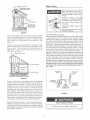
Connecting the gas piping to the gas control valve of the water
heater can be accomplished by either of the two methods
shown in Figures 19 and 20.
Contaminants in the gas lines may cause improper operation
of the gas control valve that may result in fire or explosion.
Before attaching the gas line be sure that al! gas pipe is clean
on the inside. To trap any dirt or foreign material in the gas
supply line, a drip leg (sometimes called a sediment trap)
must be incorporated in the piping. The drip leg must be readily
accessible. Install in accordance with the Gas Piping section.
Refer to the current edition of the National Fuel Gas Code,
ANSI Z223.1INFPA 54.
A sediment trap shall be installed as close to the inlet of the
water heater as practical at the time of water heater installation.
The sediment trap shall be either a tee fitting with a capped
nipple in the bottom outlet or other device recognized as an
effective sediment trap. If a tee fitting is used, it shall be installed
in conformance with one of the methods of installation, shown
in Figures 19 and 20.
GROUND JOINT -
UNION
(OPTIONAL)
CAP
FIGURE 19. GAS PIPING WITH FLEXIBLE CONNECTOR.
CAP
FIGURE 20. GAS PIPING WITH ALL
BLACK IRON PIPE TO GAS CONTROL.
17

FOR YOUR SAFETY READ BEFORE UGHTING
WARNING: If you do not follow these instructions exactly, a fire or
explosion may result causing property damage, personal injury or loss of life.
BEFORE OPERATING: ENTIRE SYSTEM MUST BE FILLED W}TH WATER AND AIR PURGED FROM ALL LINES.
A. This appliance has a pilot which is lit by a piezo electric
gas ignition system. Do not open the inner door of the
appliance and try to light the pilot by hand.
B. BEFORE UGHTING smell all around the applianoe area
for gas. Be sure to smell next to the floor because some
gas is heavier than air and will settle on the floor.
WHAT TO DO IFYOU SMELL GAS:
Do not try to light any appliance.
Do not touch any electric switch; do not use any phone
in your building.
Immediately call your gas supplier from a neighbor's
phone. Follow the gas supplier's instructions.
C.
D.
If you cannot reach your gas supplier, call the fire
department.
Use only your hand to push in or turn the gas control
knob. Never use tools. Ifthe knob will not push inor turn
by hand, don't try to repair it, call a qualified service
technician. Force or attempted repair may result in a fire
or explosion.
Do not use this appliance if any part has been under
water. Immediately contact a qualified installer or service
agency to replace a flooded water heater. Do not attempt
to repair the unit! It must be replaced!
UGHTING iNSTRUCTiONS
1,
2.
3.
4,
5.
7,
8.
FmGURE "A"
"OFF POSITION
HGURE "g" HGURE "C"
"PILOT" POSITION "ON" POSITRON
MAI_ 8U_NER
/
GAS CONTROL
TOPKNOB
FIGURr: "D"
STOPI Read the safety information
above on this label.
Set the thermostat to lowest setting (PILOT LIGHTING).
Turn thermostat dial fully clockwise t_ until it stops.
Push the gas control knob down slightly and turn clockwise
f_ to"OFF", SEE FIGURE 'W'.
NOTE: Knob CANNOT be turned from "PILOT" to "OFF"
unless it is pushed down slightly. Do not force.
Remove the outer burner door located below the gas
control.
Wait five (5) minutes to clear out any gas. If you then
smell gas, @ STOPI Follow"B" in the safety information
above on this label. If you don't smell gas, go to next step.
This unit is equipped with a push button pilot igniter, which
is used to light the pilot. Locate the igniter on the gas
control.
Turn gas control knob counterclockwise _'_ to "PILOT",
SEE FIGURE "B".
The pilot is located on the right side of the burner. It can be
located by looking through the glass view port while
pressing the piezo igniter button several times. Look for a
spark at the pilot location, FIGURE "D'.
9. Once the pilot has been found, push the gas knob all the
way down. Immediately press the pilot igniter button rapidly
(4) to (5) times. If the pilot will not light, repeat step (3)
through (9).
10. Continue to hold the gas control knob down for about one
(!) minute after the pilot is lit. Release the gas control knob
and itwill pop back up. Pilot should remain lit. If it goes out,
repeat step (3) through (9). Itmay take several minutes for
air to clear the lines before the pilot will light.
° If knob does not pop up when released, stop and
immediately call your service technician or gas supplier.
° If the pilot will not stay lit after several tries, turn the gas
control knob clockwise f_ to "OFF" and call your service
technician or gas supplier. SEE FIGURE "A".
11. Once the pilot flame is established replace the outer burner
door.
12. At arms length away, turn gas control knob
counterclockwise ('_ to "ON". SEE FIGURE "C".
13. Set thermostat to desired setting.
DANGER: Hotter water increases the risk of
scald injury. Consuk the instruction manual
before changing temperature.
_to "OFF". Do not force. SEE FIGURE "A".
18

Temperature Regulation
Due to the nature of the typical gas water heater, the water
temperature in certain situations may vary up to 30F ° (16.7 C °)
higher or lower at the point of use such as, bathtubs, showers,
sink, etc.
Any water heater's intended purpose is to heat water. Hot
water is needed for cleansing, cleaning, and sanitizing (bodies,
dishes, clothing). Untempered hot water can present a scald
hazard. Depending on the time element, and the people
involved (adults, children, elderly, infirm, etc.)scalding may occur
at different temperatures.
Water temperature over 125°F
(52°C) can cause severe burns
instantly resulting in severe injury
or death
Children, the elderly, and the
physically or mentally disabled
are at highest fiskforscald injury,
Fed water before bathing or
showering,
Temperature limiting valves are
available_
Read instruction manual for safe
temperature setting,
THE WATER HEATER SHOULD BE LOCATED IN AN AREA
WHERE THE GENERAL PUBLIC DOES NOT HAVE ACCESS.
IF ASUITABLEAREA IS NOTAVAtLABLE,A COVER SHOULD BE
INSTALLED OVER THE THERMOSTAT TO PREVENT
TAMPERING. Suitable covers are available through the Sears
Service Center.
Never allow small children to use a hot water tap, or to draw
their own bath water. Never leave a child or handicapped person
unattended in a bathtub or shower.
NOTE: A water temperature range of 120°F-140°F (49°C-60°C)
is recommended by most dishwasher manufacturers.
The thermostat of this water heater has been factory set at its
lowest position (PILOT LIGHTING). It is adjustable and must
be reset to the desired temperature setting to reduce the risk of
scald injury. The mark (A) indicative of approximately 120°F
(49°C) is preferred starting point. Some states have a
requirement for a lower setting.
Turn the water temperature dial clockwise ( G ) to decrease
the temperature, or counterclockwise ( _ ) to increase the
temperature.
Should overheating occur or the gas supply fail to shut off, turn
off the manual gas control valve to the appliance.
HOTTER WATER CAN SCALD: Water heaters are intended to
produce hot water. Water heated to a temperature which will
satisfy space heating, clothes washing, dish washing, and
other sanitizing needs can scald and permanently injure you
upon contact. Some people are more likely to be permanently
injured by hot water than others. These include the elderly,
children, the infirm, or physically/mentally handicapped. If
anyone using hot water in your home fits into one of these
groups or if there is a local code or state law requiring a certain
temperature water at the hot water tap, then you must take
special precautions. In addition to using the lowest possible
temperature setting that satisfies your hot water needs, a
means such as a mixing valve, shall be used at the hot water
taps used by these people or at the water heater. Mixing valves
are available at plumbing supply or hardware stores. Follow
manufacturer's instructions for installation of the valves. Before
changing the factory setting on the thermostat, read the
Temperature Regulation section in this manual, see Figures
21 and 22.
FIGURE 21,
VERY HOT= approx.160°F(71°C)
C = approx. 150°F (66°C)
B = approx. 140°F (60°C)
A = approx. 130°F (54'>C)
A = approx. 120°F (49°C)
LOW = approx. 80°F (27°C)
FIGURE 22.
About 1/2 second
About 1-1/2 seconds
Less than 5 seconds
About 30 seconds
More than 5 minutes
19

Tank (Sediment) C_eaning
Sediment build-up on the tank bottom may create varying
amount of noise, and if left in the tank will cause permanent
tank failure. In some water areas, you may not be able to drain
all sediment deposits by simply draining the tank. In these
cases Mag-Erad (part no. 23600) can be used to help remove
the sediment deposits. This may be ordered from the Sears
Service Center. For ordering, refer to the Parts Order List
section.
Vent System _nspection
Carbon Monoxide and Fire Hazard
Flue gases may escape if vent pipe
is not connected.
o Be alert for obstructed, sooted or
deteriorated vent system to avoid
serious injury or death.
Do not store corrosive chemicals
in vicinity of water heater.
Chemical corrosion of flue and vent
system can cause serious injury or
death
Breathing carbon monoxide can cause brain damage or
death Ak_ays read and understand instruction manual
Burner Inspection
Flood damage to a water heater may not be readily visible or
immediately detectable. However, over a period of time a
flooded water heater will create dangerous conditions which
can cause DEATH, SERIOUS BODILY INJURY, OR PROPERTY
DAMAGE. Contact a Sears Service Center to replace a flooded
water heater. Do not attempt to repair the unit! It must be
replaced!
At least once a year a visual inspection should be made of the
main burner and pilot burner, see Figure 23.
You should check for sooting. Soot is not normal and will impair
proper combustion.
Soot build-up indicates a problem that requires correction
before further use. Turn 'OFF" gas to water heater and
leave off until repairs are made, because failure to correct the
cause of the sooting can result in a fire causing death, serious
injury, or property damage.
FIGURE23.
Burner C_eaning
At least once a year a visual inspection should be made of the
venting system. You should look for:
Obstructions which could cause improper venting. The
combustion and ventilation air flow must not be obstructed.
Damage or deterioration which could cause improper
venting or leakage of combustion products.
Rusted flakes around top of water heater.
Be sure the vent piping is properly connected to prevent escape
of dangerous flue gasses which could cause deadly
asphyxiation.
Obstructions and deteriorated vent systems may present
serious health risk or asphyxiation.
Chemical vapor corrosion of the flue and vent system may
occur if air for combustion contains certain chemical vapors.
Spray can propellants, cleaning solvents, refrigerator and air
conditioner refrigerants, swimming poo! chemicals, calcium
and sodium chloride, waxes, bleach and process chemicals
are typical compounds which are potentially corrosive.
If when inspecting the vent system you find sooting or
deterioration, something is wrong_ Call the local gas supplier
to correct the problem and clean or replace the flue and venting
before resuming operation of the water heater.
Fire or Explosion Hazard
Failure to properly reseal the combustion chamber will
disable the flammable vapor ignition resistance feature
of this water heater, which could result in death or serious
injury Contact your local Sears Service Center
for assistance
Read instruction manual before
installing, using or serwcmg
water heater,
2O
In the event your burner needs cleaning, following these
instructions:
If inspection of the burner shows that cleaning is required, turn
the gas control knob clockwise ( r'_ ) to the 'OFF" position,
depressing slightly.
NOTE: The knob cannot be turned from "PmLOT" to "OFF"
unless knob is depressed siightmy. DO NOT FORCE.
The burner needs to be removed for cleaning. Cal! the Sears
Service Center to remove and clean the burner and correct the
problem that required the burner to be cleaned.
Page is loading ...
Page is loading ...
Page is loading ...
Page is loading ...
Page is loading ...
Page is loading ...
Page is loading ...
Page is loading ...
Page is loading ...
Page is loading ...
Page is loading ...
Page is loading ...
-
 1
1
-
 2
2
-
 3
3
-
 4
4
-
 5
5
-
 6
6
-
 7
7
-
 8
8
-
 9
9
-
 10
10
-
 11
11
-
 12
12
-
 13
13
-
 14
14
-
 15
15
-
 16
16
-
 17
17
-
 18
18
-
 19
19
-
 20
20
-
 21
21
-
 22
22
-
 23
23
-
 24
24
-
 25
25
-
 26
26
-
 27
27
-
 28
28
-
 29
29
-
 30
30
-
 31
31
-
 32
32


Kenmore POWER MISER 6 153.336466 User manual
- Category
- Water heaters & boilers
- Type
- User manual
Ask a question and I''ll find the answer in the document
Finding information in a document is now easier with AI
Related papers
-
Kenmore 6-Year Manufacturer's Warranty
-
-
Kenmore Gas Heater 153.33096 User manual
-
-
-
-
-
-
-
Other documents
-
American Water Heater VG6250T100 User manual
-
A.O. Smith 185363-001 User manual
-
State Industries 9211814006 User manual
-
A.O. Smith 100274381 Installation guide
-
-
Whirlpool 318935-003 User manual
-
Apollo Hydroheat A650YRRTL5 User manual
-
-
-