Page is loading ...

20402 & 29402
VATS / PASSLOCK / TRANSPONDER
Universal Alarm Bypass Module
English p1
Français p17
Español p29

© 2006 Directed Electronics 1 N20402 08-06
VATS / PASSLOCK / TRANSPONDER
Universal Alarm Bypass Module
Model #s 20402 & 29402
This module lets you bypass virtually any type of factory passive anti-theft system
on the market today to remotely start your vehicle without permanently disabling
the vehicle’s anti-theft system.
In 1983, General Motors came out with their rst Vehicle Anti- Theft System
known as VATS which uses a resistor pellet in the key. Since that time, other more
sophisticated theft systems have followed. These theft systems are still resistance
based, and use a “Transponder” which is a tiny pellet or chip embeded within the
the head of the ignition key.
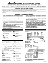
Contents:
1 Universal Alarm Bypass Module
1 8 position wire harness
1 Transponder loop w/connector
2 Cable Ties
1 Instruction booklet
2 Double-stick foam tape
8 position harness
connector
Transponder Loop
connector
2 Resistor
Measuring Pads
8 position
dip-switch
Variable Resistor
FRONT VIEW
BACK VIEW
Up is OFF
Down is ON
1 2 3 4 5 6 7 8

N20402 08-06 2 © 2006 Directed Electronics
List of vehicles and the types of security systems
Lista de Vehículos y tipos de sistemas de seguridad:
Make Model Year Immobilizer
Type
Cadillac Escalade Ext 2002-06 Passlock II
Cadillac Seville 1998-2004 Transponder
Cadillac SRX 2004-06 Transponder
Cadillac Catera 1997-2001 Transponder
Cadillac DTS 2006 Transponder
Cadillac SRX 2004-06 Transponder
Cadillac Allante 1991-93 VATS
Cadillac Brougham 1990-95 VATS
Cadillac De Ville 1990-99 VATS
Cadillac Eldorado 1990-2002 VATS
Cadillac Fleetwood 1990-96 VATS
Cadillac Seville 1990-97 VATS
Chevrolet Astro 1998-2005 Passlock II
Chevrolet Avalanche 2002-06 Passlock II
Chevrolet Blazer 1998-2005 Passlock II
Chevrolet Express Van 1998-2006 Passlock II
Chevrolet Impala 2000-06 Passlock II
Chevrolet Monte Carlo 2000-05 Passlock II
Chevrolet S-10 Pickup 1998-2004 Passlock II
Chevrolet Silverado 1999-2006 Passlock II
Chevrolet Suburban 1998-2006 Passlock II
Chevrolet Tahoe 1998-2006 Passlock II
Chevrolet Trailblazer 2002-06 Passlock II
Chevrolet Venture 2000-05 Transponder
Chevrolet Cavalier 1995-2005 Passlock I
Chevrolet Equinox 2005-06 Passlock II
Chevrolet Malibu 1997-2006 Passlock II
Chevrolet Monte Carlo 2000-05 Passlock II
Chevrolet S-10 Pickup 1998-2004 Passlock II
Chevrolet Silverado 1998-2005 Passlock II
Chevrolet SSR 2003-06 Passlock II
Chevrolet Aveo 2004-06 Transponder
Chevrolet Impala 2006 Transponder
Chevrolet Uplander 2005-06 Transponder
Make Model Year Immobilizer
Type
Acura CL 1998-2003 Transponder
Acura Integra 2000-01 Transponder
Acura MDX 2001-06 Transponder
Acura TL 1999-2006 Transponder
Acura TSX 2004-06 Transponder
Acura NSX 1997-2005 Transponder
Acura RL 1996-2004 Transponder
Audi A4 2000-04 Transponder
Audi A6 2000-04 Transponder
Audi A8 2000-03 Transponder
Audi Allroad 2001-04 Transponder
Audi S4 2002 Transponder
Audi TT 2000-04 Transponder
Buick LaCrosse 2005-06 Transponder
Buick LeSabre 2000-05 Transponder
Buick Park Avenue 2000-05 Transponder
Buick Rainier 2004-06 Passlock II
Buick Rendezvous 2002-06 Transponder
Buick LeSabre 2000-05 Transponder
Buick Park Avenue 1997-2005 Transponder
Buick Skylark 1996-98 Passlock I
Buick LaCrosse 2005-06 Transponder
Buick Lucerne 2006 Transponder
Buick Terraza 2005-06 Transponder
Buick Century 1993 VATS
Buick Century 1994-2005 VATS
Buick Reatta 1990-91 VATS
Buick Regal 1993-2004 VATS
Buick Riviera 1990-99 VATS
Buick Roadmaster 1993-96 VATS
Cadillac CTS 2003-06 Transponder
Cadillac De Ville 2000-05 Transponder
Cadillac Escalade 1999-2006 Passlock II
Cadillac Escalade ESV 2003-06 Passlock II
Liste de véhicules avec leurs types de systèmes de sécurité
English Français
Transponder = Transpondeur
VATS = SAV

© 2006 Directed Electronics 3 N20402 08-06
Chevrolet Camaro 1986-2002 VATS
Chevrolet Caprice 1993-96 VATS
Chevrolet Corvette 1984-2004 VATS
Chevrolet Impala 1994-96 VATS
Chevrolet Lumina 1993-2000 VATS
Chevrolet Monte Carlo 1995-99 VATS
Chevrolet Monte Carlo 2001-06 Passlock II
Chrysler 300M 1999-2004 Transponder
Chrysler Cirrus 2000 Transponder
Chrysler Concorde 1998-2004 Transponder
Chrysler LHS 1999-2001 Transponder
Chrysler Prowler 2001-02 Transponder
Chrysler PT Cruiser 2001-05 Transponder
Chrysler Sebring Convert-
ible
1998-2005 Transponder
Chrysler Sebring Sedan 2001-05 Transponder
Chrysler Town and Country 2001-03 Transponder
Chrysler Voyager 2001-03 Transponder
Chrysler 300 2005-06 Transponder
Chrysler Pacica 2004-06 Transponder
Chrysler PT Cruiser 2006 Transponder
Chrysler Town and Country 2004-05 Transponder
Chrysler Crossre 2004-05 Transponder
Chrysler Sebring Coupe 2001-05 Transponder
Dodge Caravan 2001-03 Transponder
Dodge Dakota pickup 2001-04 Transponder
Dodge Durango 2001-03 Transponder
Dodge Intrepid 1998-2004 Transponder
Dodge Neon 2000-05 Transponder
Dodge Ram Pickup 2002-05 Transponder
Dodge Stratus 2000 Transponder
Dodge Stratus Sedan 2001-05 Transponder
Dodge Caliber 2007 Transponder
Dodge Caravan 2004-05 Transponder
Dodge Charger 2006 Transponder
Dodge Dakota pickup 2005 Transponder
Dodge Magnum 2005-06 Transponder
Dodge Durango 2004-06 Transponder
Dodge Ram Pickup 2006 Transponder
Dodge Sprinter 2003-05 Transponder
Dodge Stratus Coupe 2001-05 Transponder
Ford Contour 1998-2000 Transponder
Ford Crown Victoria 1998-2006 Transponder
Ford Escape 2001-06 Transponder
Ford Excursion 2000-05 Transponder
Ford Expedition 1997-2006 Transponder
Ford Explorer 1998-2006 Transponder
Ford Explorer Sport
Trac
2001-05 Transponder
Ford F Series Light
Duty
1998-2006 Transponder
Ford Five Hundred 2005-06 Transponder
Ford Focus 2000-06 Transponder
Ford Freestar 2004-06 Transponder
Ford Freestyle 2005-06 Transponder
Ford Fusion 2006 Transponder
Ford GT 2005-06 Transponder
Ford Mustang 1996-2006 Transponder
Ford Ranger 1998-2006 Transponder
Ford Taurus 1998-2006 Transponder
Ford Thunderbird 1997,
2002-05
Transponder
Ford Windstar 1999-2003 Transponder
Ford Taurus 1996-97 Transponder
GMC Denali 1999-2001 Passlock II
GMC Envoy 1999-2006 Passlock II
GMC Envoy XL 2002-06 Passlock II
GMC Envoy XUV 2004-05 Passlock II
GMC Safari 1998-2005 Passlock II
GMC Safari 2005 Passlock II
GMC Savana Van 1998-2006 Passlock II
GMC Sierra 1998-2006 Passlock II
GMC Sonoma 1998-2004 Passlock II
GMC Yukon 1999-2006 Passlock II
GMC Yukon XL 2000-06 Passlock II
GMC Jimmy 1998-2001 Passlock II
GMC Suburban 1998-2006 Passlock II
Honda Prelude 1997-2001 Transponder
Honda Accord 1998-2006 Transponder
Honda Civic 2001-06 Transponder
Honda CR-V 2002-06 Transponder
Honda Element 2003-05 Transponder
Honda Fit 2007 Transponder
Honda Odyssey 1999-2006 Transponder
Honda Pilot 2003-05 Transponder
Honda Ridgeline 2006 Transponder
Honda Accord Hybrid 2005 Transponder
Honda Insight 2000-05 Transponder
Honda Odyssey 1998 Transponder

© 2006 Directed Electronics 5 N20402 08-06
Mercedes
Benz
C 280 1998-2000 SWITCH-
BLADE
KEYS ONLY
Mercedes
Benz
C Class 2001-02 SWITCH-
BLADE
KEYS ONLY
Mercedes
Benz
CL Class 1998-99 SWITCH-
BLADE
KEYS ONLY
Mercedes
Benz
CLK Class 1998 SWITCH-
BLADE
KEYS ONLY
Mercedes
Benz
CLK Class 1999-2002 SWITCH-
BLADE
KEYS ONLY
Mercedes
Benz
E Class 1997-2002 SWITCH-
BLADE
KEYS ONLY
Mercedes
Benz
ML 320 1998-2000 SWITCH-
BLADE
KEYS ONLY
Mercedes
Benz
ML 430 1999-2000 SWITCH-
BLADE
KEYS ONLY
Mercedes
Benz
ML Class 2001-02 SWITCH-
BLADE
KEYS ONLY
Mercedes
Benz
S 320 1997 SWITCH-
BLADE
KEYS ONLY
Mercedes
Benz
S 420 1997 SWITCH-
BLADE
KEYS ONLY
Mercedes
Benz
S 500 1997 SWITCH-
BLADE
KEYS ONLY
Mercedes
Benz
S Class 1998-2002 SWITCH-
BLADE
KEYS ONLY
Mercedes
Benz
SL Class 1998-99 SWITCH-
BLADE
KEYS ONLY
Mercedes
Benz
SLK Class 1998-2002 SWITCH-
BLADE
KEYS ONLY
Mercury Cougar 1999-2002 Transponder
Mercury Grand Marquis 1999-2006 Transponder
Mercury Marauder 2003-04 Transponder
Mercury Mariner 2005-06 Transponder
Mercury Milan 2006 Transponder
Mercury Montego 2005-06 Transponder
Mercury Monterey 2004 Transponder
Mercury Monterey 2005-06 Transponder
Mercury Mountaineer 1998-2006 Transponder
Mercury Mystique 1998-2000 Transponder
Mercury Sable 1996-2005 Transponder
Mercury Cougar 1997 Transponder
Mercury Grand Marquis 1998 Transponder
Mercury Mountaineer 1997 Transponder
Mini Cooper 2002-05 Transponder
Mitsubishi Diamante 2000-04 Transponder
Mitsubishi Eclipse 2000-06 Transponder
Mitsubishi Endeavor 2004-05 Transponder
Mitsubishi Galant 2000-05 Transponder
Mitsubishi Lancer 2003-05 Transponder
Mitsubishi Montero 2001-05 Transponder
Mitsubishi Montero Sport 2000-04 Transponder
Mitsubishi Outlander 2004-05 Transponder
Mitsubishi Raider 2006 Transponder
Nissan 350Z 2003-05 Transponder
Nissan Altima 2000-05 Transponder
Nissan Armada 2005 Transponder
Nissan Frontier 2005 Transponder
Nissan Maxima 1999-2005 Transponder
Nissan Murano 2003-05 Transponder
Nissan Pathnder 1999-2005 Transponder
Nissan Pathnder 2000-05 Transponder
Nissan Pathnder Armada 2004 Transponder
Nissan Quest 2004-05 Transponder
Nissan Sentra 2000-05 Transponder
Nissan Titan 2004-05 Transponder
Nissan Xterra 2005 Transponder
Oldsmobile Alero 2000-04 Passlock II
Oldsmobile Aurora 1995-99 VATS
Oldsmobile Aurora 2001-03 Transponder
Oldsmobile Bravada 1999-2004 Passlock II
Oldsmobile Intrigue 1998-2002 Passlock II
Oldsmobile Silhouette 2000-04 Transponder
Oldsmobile Achieva 1996-98 Passlock I
Oldsmobile Cutlass 1997-99 Passlock II
Oldsmobile Cutlass Ciera 1995-96 VATS
Oldsmobile Cutlass Supreme 1995-97 VATS
Oldsmobile Eighty-Eight 1995-97 VATS
Oldsmobile Eighty-Eight LSS 1998-99 VATS
Oldsmobile Ninety-Eight 1992-98 VATS
Oldsmobile Regency 1997-98 VATS
Plymouth Breeze 2000 Transponder
Plymouth Neon 2000-01 Transponder
Plymouth Prowler 1999-2000 Transponder
Pontiac Aztek 2001-05 Passlock II
Pontiac Bonneville 1992-2005 VATS
Pontiac Grand Am 1996-98 Passlock I

© 2006 Directed Electronics 7 N20402 08-06
Determine which type system you have in your vehicle. If unsure -- follow the
chart on the previous pages to determine the system you have. There are several
types of systems as outlined below:
General Motors VATS and PASSLOCK 1 and PASSLOCK 2 theft systems. For
these, you will be required to dial-in a resistor value which matches the one on your
security system. The method is described on the following pages for each type
system using the dip switches and the variable resistor. The variable resistor is a
10 turn potentiometer which can be dialed up from zero ohms to 1,000 ohms.
SATURN vehicles up to the 2000 model year simply hook up to the Universal
Alarm Bypass Module as shown on page 13. If you have a 2000 model year or
later Saturn vehicle, see page 14.
TRANSPONDER / PASSKEY 3 / P.A.T.S. systems require a transponder (or
extra key) to be used with our system. Follow the directions beginning on page
14.

N20402 08-06 8 © 2006 Directed Electronics
Dip Switch # 2 3 4 5 6
Resistor Value 0.825 1.65 3.32 6.65 13.3 Final Resistance (k ohms)
ON ON ON ON ON 0.000 +Variable Resistor Value
OFF ON ON ON ON 0.825 +Variable Resistor Value
ON OFF ON ON ON 1.650 +Variable Resistor Value
OFF OFF ON ON ON 2.475 +Variable Resistor Value
ON ON OFF ON ON 3.320 +Variable Resistor Value
OFF ON OFF ON ON 4.145 +Variable Resistor Value
ON OFF OFF ON ON 4.970 +Variable Resistor Value
OFF OFF OFF ON ON 5.795 +Variable Resistor Value
ON ON ON OFF ON 6.650 +Variable Resistor Value
OFF ON ON OFF ON 7.475 +Variable Resistor Value
ON OFF ON OFF ON 8.300 +Variable Resistor Value
OFF OFF ON OFF ON 9.125 +Variable Resistor Value
ON ON OFF OFF ON 9.970 +Variable Resistor Value
OFF ON OFF OFF ON 10.795 +Variable Resistor Value
ON OFF OFF OFF ON 11.620 +Variable Resistor Value
OFF OFF OFF OFF ON 12.445 +Variable Resistor Value
ON ON ON ON OFF 13.300 +Variable Resistor Value
OFF ON ON ON OFF 14.125 +Variable Resistor Value
ON OFF ON ON OFF 14.950 +Variable Resistor Value
OFF OFF ON ON OFF 15.775 +Variable Resistor Value
ON ON OFF ON OFF 16.620 +Variable Resistor Value
OFF ON OFF ON OFF 17.445 +Variable Resistor Value
ON OFF OFF ON OFF 18.270 +Variable Resistor Value
OFF OFF OFF ON OFF 19.095 +Variable Resistor Value
ON ON ON OFF OFF 19.950 +Variable Resistor Value
OFF ON ON OFF OFF 20.775 +Variable Resistor Value
ON OFF ON OFF OFF 21.600 +Variable Resistor Value
OFF OFF ON OFF OFF 22.425 +Variable Resistor Value
ON ON OFF OFF OFF 23.270 +Variable Resistor Value
OFF ON OFF OFF OFF 24.095 +Variable Resistor Value
ON OFF OFF OFF OFF 24.920 +Variable Resistor Value
OFF OFF OFF OFF OFF 25.745 +Variable Resistor Value
DipSwitch #1 Dip Switch #7 Dip Switch #8
VATS OFF OFF OFF
PASSLOCK 1 ON ON OFF
PASSLOCK 2 OFF OFF OFF
Use this chart with VATS, PASSLOCK 1 and PASSLOCK 2.
All resistor values shown are in ‘K-ohms’ -- or 1,000 ohms. Thus the
1.650 value shown in the third row is 1,650 ohms or 1.65 K ohms.

© 2006 Directed Electronics 9 N20402 08-06
VATS:
Before performing this set up, make sure the vehicle will start with the transmitter
if you leave the ignition key in the key cylinder.
1. Put dip switch 1, 7 and 8 into the OFF (up) position
2. Measure the resistance of the key. It should be between 392 ohms and 11,800
ohms. To do this, put the ohm meter probes on each side of the key pellet. This
value should be close to one of the following (all values in ohms): 392, 523, 681,
887, 1.13K, 1.47K, 1.87K, 3.01K, 3.74K, 4.75K, 6.04K, 7.5K, 9.53K, 11.8K.
3. Locate the closest value which is less than your desired value on the chart on
page 8. Set dip-switches 2 through 6 as shown on page 8.
4. Put your ohm meter (multi-meter) probes on the two silver resistance measuring
pads through the opening shown in the drawing -- making good contact with
these two silver pads on the board. (See drawing on page 1). Or put your two
probes into the two holes on the bottom of the case making contact with the
underside of the silver pads. Either contact point method will work.
5. With the probes held rmly, nish reaching the nal resistance value needed
for your system by turning the screw on the variable resistor on the side of the
unit next to the dip switches. Turn the screw until the resistance value matches
the resistance value of the key.
6. Locate the pair of VATS wires (sometimes White/Black striped and Purple/
Black striped). These wires are often in a plastic tube. Be careful not to cut
into the Yellow Air Bag wires! The Air Bag wires are often in a yellow plastic
tube that is clearly marked. The VATS wires run from the ignition switch down
the column under the dash. Connect the Universal Alarm Bypass Module using
the diagram below.
Dip Switch #1 Off
Dip Switch #7 Off
Dip Switch #8 Off
*See page 16 if you do not have a Status wire on your remote
starter
White/Green to Status wire

N20402 08-06 10 © 2006 Directed Electronics
PASSLOCK 1:
1. Put dip switches 1 and 7 in the ON (down) position and dip switch 8 in the OFF
(up) position.
2. Remove the bottom half of the steering column shroud.
3. Locate the small three wire harness (with White, Black and Yellow wires)
running down from the ignition key cylinder on the top right hand side of the
steering column into the instrument panel. These wires are usually the smallest
wires in the harness.
4. Cut the Yellow wire in half and strip back both ends. Remove some of the
insulation on the Black wire without cutting the wire. The White wire is not
used.
5. Turn the ignition key to the “ON” or “RUN” position and place the vehicle into
reverse.
6. With the ignition key still in and turned to the “RUN” position, measure the
resistance between the key side of the Yellow wire (connected to the + positive
lead of your digital meter) and the Black wire (connected to the - negative side
of your digital meter).
7. Turn the ignition key to the “START” position and release it. Denote the
resistance reading as this will be the resistance that will need to be duplicated.
Repeat this step several times to verify that you have a consistent reading.
8. When you have identied the correct resistance use the chart on page 8 to set
the resistance on the bypass module. Locate the closest value which is less than
your desired value. Set dip-switches 2 through 6 to match the chart on page 8
for this value.
9. Put your ohm meter (multi-meter) probes on the two silver resistance measuring
pads through the opening shown in the drawing -- making good contact with
these two silver pads on the board. (See drawing on page 1). Or put your two
probes into the two holes on the bottom of the case making contact with the
underside of the silver pads. Either contact point method will work.
10. With the probes held rmly -- dial-in the nal resistance value needed for your
system by turning the screw on the variable resistor on the side of the unit
next to the dip switches. Turn the screw until the resistance value matches the
resistance value of the key.
11. Locate the Black “Bulb Test” wire on the left side of the steering column in
cavity “D” or “E” of the Black 5-way connector, just above the main ignition
switch connector. This is a different wire than the Black wire mentioned in
the above steps.
12. Connect the bypass module using the diagram below. Be sure to tape over any
connections to not leave any exposed wires.

© 2006 Directed Electronics 11 N20402 08-06
PASSLOCK 2:
1. Turn dip switches 1, 7, and 8 to the OFF (up) position.
2. Remove the bottom half of the steering column shroud.
3. Locate the small three wire harness (with Red/White, Yellow and Orange/
Black wires on trucks and White, Yellow and Black on cars) that come
off the ignition lock cylinder. These are usually the smallest wires.
4. Cut the Yellow wire in half and strip back both ends. Remove the insulation
on the Orange/Black wire (trucks) or the Black wire (cars) without cutting
the wire. The Red/White or White wire is not used.
5. Turn the key to the “Run” position and place the vehicle in Reverse.
6. Connect the key side of the Yellow wire to the + positive lead of your digital
meter and the Black wire (cars) or Orange/Black wire (trucks) to the - nega-
tive lead of your digital meter.
7. Turn the ignition key to the “START” position and release it. Denote the
resistance reading as this will be the resistance that will need to be duplicated.
Repeat this step several times to verify that you have a consistent reading.
*See page 16 if you do not have a Status wire
PASSLOCK 1
To verify the Passlock 1 installation has the correct resistance value
and that the installation is correct -- hold the WHITE/GREEN wire
to ground and start the vehicle with the key. If the vehicle starts
and stays running - the installation is correct.
WHITE/GREEN to WHITE/
BLACK Status wire from
the remote starter.*

N20402 08-06 12 © 2006 Directed Electronics
*See page 16 if you do not have a Status wire
Dip Switch #1 Off
Dip Switch #7 Off
Dip Switch #8 Off
8. When you have identied the correct resistance use the chart on page 8 to set
the resistance on the bypass module. Locate the closest value which is less
than your desired value. Set dip-switches 2 through 6 to match the chart on
page 8 with this value.
9. Put your ohm meter (multi-meter) probes on the two silver resistance measuring
pads through the opening shown in the drawing -- making good contact with
these two silver pads on the board. (See drawing on page 1). Or put your two
probes into the two holes on the bottom of the case making contact with the
underside of the silver pads. Either contact point method will work.
10. With the probes held rmly -- dial-in the nal resistance value needed for your
system by turning the screw on the variable resistor on the side of the unit
next to the dip switches. Turn the screw until the resistance value matches
the resistance value of the key.
11. Connect the bypass module using the diagram on the next page. Be sure to
tape over any connections to not leave any exposed wires.
To verify that this installation is correct -- hold the WHITE/GREEN wire
and the GRAY/BLACK wire to ground and start the vehicle with the key.
If the vehicle starts and stays running - the installation is correct.
WHITE/GREEN TO WHITE/BLACK
Status output from car starter
(or to constant negative ground
output when remote starter is

© 2006 Directed Electronics 13 N20402 08-06
SATURN:
Saturn vehicles up to the 2000 model year with factory keyless entry have a
unique bypass.
1. Set all dip switches to the OFF (up) position.
2. Locate the Alarm Module behind the right rear quarter trim panel (trunk area).
Connect the Pink and Yellow/Black wires of Connector J and D of the alarm
module as shown.
3. Cut the Pink wire in half and connect as shown.
*See page 16 if you do not have a Status wire
Dip Switch #1 Off
Dip Switch #7 Off
Dip Switch #8 Off
WHITE/GREEN TO WHITE/BLACK
Status output from car starter (or
to constant negative ground output
when remote starter is activated).*

N20402 08-06 14 © 2006 Directed Electronics
TRANSPONDER / PASSKEY 3 / P.A.T.S.:
‘Smart Key’ & other Transponder systems
Note: For this type of security system - you must sacrice one of the spare keys that
comes with the car. This key will be used for the transponder. The dealership
can progam a spare key, but make sure they program all keys to the vehicle
since learning just one transponder could erase all other key transponders
(including the key used for the Bypass Module).
1. Set all dip switches on the bypass module to the OFF (up) position.
2. Remove the transponder from the key (there maybe a door on the top of the
key that can be opened and the transponder can be removed). Or, the entire
key may be mounted inside the Bypass Module. Be sure to cut the key in half
or grind off some of the teeth to render it unusable.
3. Pull apart the case and place the transponder, or the head of the key, inside the
10 wire loop on the circuit board. Transponders are directional and must be
placed along the same direction that the key would lay. Use the double stick
foam tape provided -- one layer on the circuit board and then the transponder,
or key, and nally the second double-stick foam tape layer on top of it to
hold key securly in place. Make sure the white wires inside the module do not
crisscross each other.
Place Key with Transponder inside case on pc
board as shown. Use double stick tape to hold
to the key in place.

© 2006 Directed Electronics 15 N20402 08-06
4. The transponder LOOP goes underneath the steering column and up toward
the ignition key cylinder and needs to be positioned so that there are 2 turns
around the ignition key cylinder as shown below. Transponder systems often
have a black plastic ring around the ignition lock switch. This is the vehicle’s
transponder pick-up antenna. It is important that the two loops of the Bypass
Module be mounted on or as close to this black plastic ring as possible. Slide
the tube up toward the ignition switch to tighten up the loops of wire. Tape in
place to hold. Plug the other end of the transponder loop into the Universal
Alarm Bypass Module.
5. Now start the vehicle with the remote starter. If the vehicle starts and runs
for at least 30 seconds the transponder bypass is correct. Note: If the vehicle
does not start with the remote starter, try adjusting or changing the position
of the transponder in the Bypass Module or adjusting the position of the two
loop wire around the transponder pick-up antenna mentioned above.
Note: The key that the transponder was removed from will no longer start
the vehicle.
White/Green to Status wire of Remote Starter

N20402 08-06 16 © 2006 Directed Electronics
For Car Starters that do not have a Status output: You will need a Status
output from your remote car starter for each kind of immobilizer listed on the
preceding pages. Most of our remote starters use the WHITE/BLACK wire in the
control harness as the Status output. If you have a brand of remote car starter that
does not have a Status output, follow the relay hook-up below using Bosch 30 Amp
relays for creating the Status output.
Status output to control
alarm bypass module

41
LIMITED ONE YEAR CONSUMER WARRANTY:
For a period of ONE YEAR from the date of purchase of a Directed Electronics remote start
or security product, Directed Electronics. (“DIRECTED”) promises to the original purchaser,
to repair or replace with a comparable reconditioned piece, the security or remote start
accessory piece (hereinafter the “Part”), which proves to be defective in workmanship
or material under normal use, provided the following conditions are met: the Part was
purchased from an authorized DIRECTED dealer; and the Part is returned to DIRECTED,
postage prepaid, along with a clear, legible copy of the receipt or bill of sale bearing the fol-
lowing information: consumer’s name, address, telephone number, the authorized licensed
dealer’s name and complete product and Part description.
This warranty is nontransferable and is automatically void if the Part has been modified or
used in a manner contrary to its intended purpose or the Part has been damaged by ac-
cident, unreasonable use, neglect, improper service, installation or other causes not arising
out of defect in materials or construction.
TO THE MAXIMUM EXTENT ALLOWED BY LAW, ALL WARRANTIES, INCLUDING BUT NOT
LIMITED TO EXPRESS WARRANTY, IMPLIED WARRANTY, WARRANTY OF MERCHANTABIL-
ITY, FITNESS FOR PARTICULAR PURPOSE AND WARRANTY OF NONINFRINGEMENT OF
INTELLECTUAL PROPERTY, ARE EXPRESSLY EXCLUDED; AND
DIRECTED NEITHER ASSUMES NOR AUTHORIZES ANY PERSON OR ENTITY TO ASSUME
FOR IT ANY DUTY, OBLIGATION OR LIABILITY IN CONNECTION WITH ITS PRODUCTS.
DIRECTED HEREBY DISCLAIMS AND HAS ABSOLUTELY NO LIABILITY FOR ANY AND ALL
ACTS OF THIRD PARTIES INCLUDING DEALERS OR INSTALLERS. IN THE EVENT OF A
CLAIM OR A DISPUTE INVOLVING DIRECTED OR ITS SUBSIDIARY, THE PROPER VENUE
SHALL BE SAN DIEGO COUNTY IN THE STATE OF CALIFORNIA. CALIFORNIA STATE LAWS
AND APPLICABLE FEDERAL LAWS SHALL APPLY AND GOVERN THE DISPUTE. THE MAXI-
MUM RECOVERY UNDER ANY CLAIM AGAINST DIRECTED SHALL BE STRICTLY LIMITED
TO THE AUTHORIZED DIRECTED DEALER’S PURCHASE PRICE OF THE PART. DIRECTED
SHALL NOT BE RESPONSIBLE FOR ANY DAMAGES WHATSOEVER, INCLUDING BUT NOT
LIMITED TO, ANY CONSEQUENTIAL DAMAGES, INCIDENTAL DAMAGES, DAMAGES FOR
THE LOSS OF TIME, LOSS OF EARNINGS, COMMERCIAL LOSS, LOSS OF ECONOMIC OP-
PORTUNITY AND THE LIKE. NOTWITHSTANDING THE ABOVE, THE MANUFACTURER DOES
OFFER A LIMITED WARRANTY TO REPLACE OR REPAIR AT DIRECTED’S OPTION THE PART
AS DESCRIBED ABOVE.
Some states do not allow limitations on how long an implied warranty will last or the exclu-
sion or limitation of incidental or consequential damages. This warranty gives you specific
legal rights and you may also have other rights that vary from State to State. DIRECTED
does not and has not authorized any person or entity to create for it any other obligation,
promise, duty or obligation in connection with this Part.
IMPORTANT NOTE:
This product warranty is automatically void if its date code or serial number is defaced,
missing, or altered.
Make sure you have all of the following information from your dealer:
A clear copy of the sales receipt, showing the following:
• Date of purchase
• Authorized dealer’s company name and address
• Item number
/