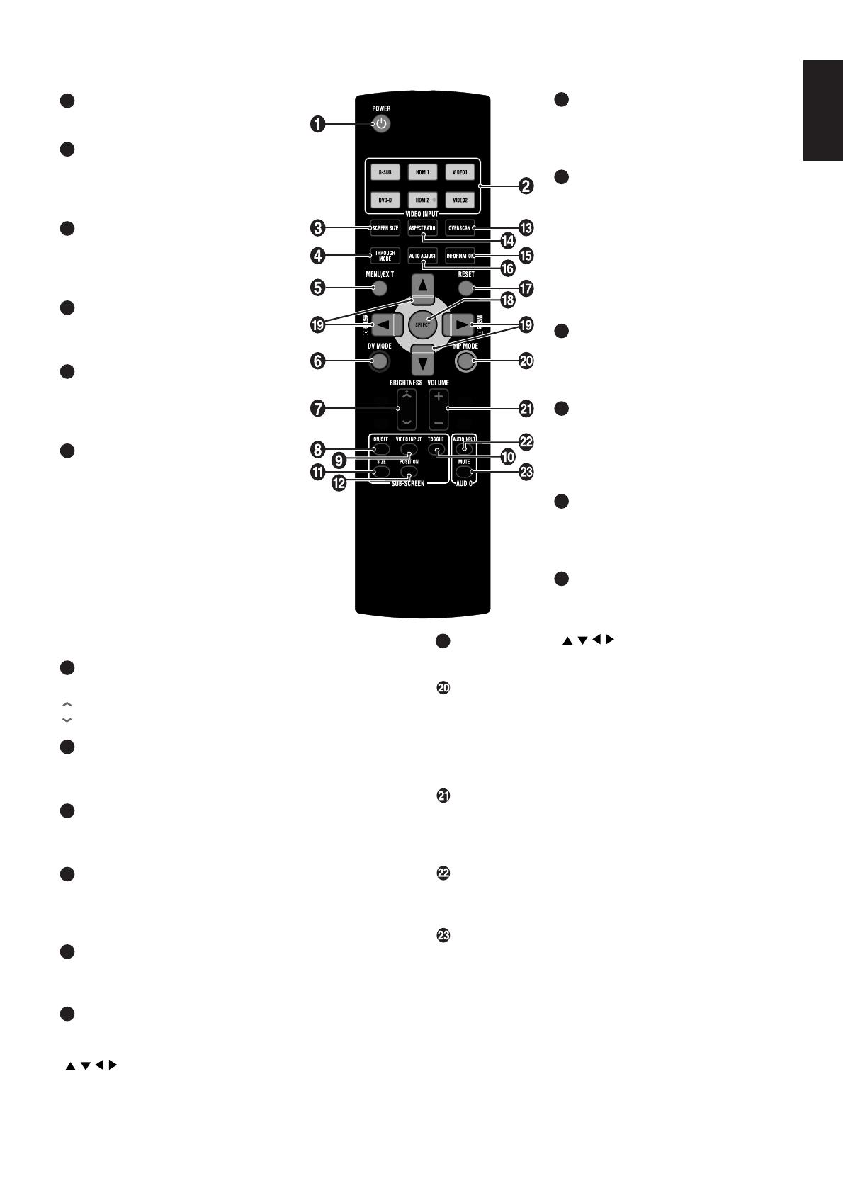
NEC MultiSync® 24WMGX³ Owner's manual

Category
TVs & monitors
Type
Owner's manual
MultiSync 24WMGX
3
Users Manual
Index
Important Information ................................................................................................................................... English-1
Registration Information ............................................................................................................................... English-1
Preparation .................................................................................................................................................. English-3
What You Can Do with This Monitor… ............................................................................................... English-3
Accessories ........................................................................................................................................ English-4
Part Names and Functions .......................................................................................................................... English-5
Front Panel ......................................................................................................................................... English-5
Rear Panel ......................................................................................................................................... English-6
Remote Control .................................................................................................................................. English-7
Operating the Remote Control ........................................................................................................... English-8
Getting Started ............................................................................................................................................. English-9
Preparation ......................................................................................................................................... English-9
Connection Types ............................................................................................................................... English-10
Making Connections ........................................................................................................................... English-11
Setting Up .................................................................................................................................................... English-17
Performing Auto Adjust (PC Analog Connection Only) ....................................................................... English-17
Playing Games and Watching DVDs .................................................................................................. English-19
Monitor Settings (OSD Functions) ............................................................................................................... English-20
OSD Screen Operations ..................................................................................................................... English-21
Options for OSD Functions (for PC Input) .......................................................................................... English-23
Options for OSD Functions (for HDMI and Video Input) .................................................................... English-30
When OSD Functions Are Required ................................................................................................... English-33
Other Functions ........................................................................................................................................... English-34
Recommended use ...................................................................................................................................... English-35
Troubleshooting ........................................................................................................................................... English-37
If you are experiencing trouble… ....................................................................................................... English-37
Appendix ...................................................................................................................................................... English-41
Installing a Monitor Arm ...................................................................................................................... English-43
Terminology .................................................................................................................................................. English-45
Specifications ............................................................................................................................................... English-47
TCO’06 ....................................................................................................................................................... English-48
Manufacturer’s Recycling and Energy Information ...................................................................................... English-49
English-1
English
Important Information
TO PREVENT FIRE OR SHOCK HAZARDS, DO NOT EXPOSE THIS UNIT TO RAIN OR MOISTURE. ALSO, DO NOT
USE THIS UNIT’S POLARIZED PLUG WITH AN EXTENSION CORD RECEPTACLE OR OTHER OUTLETS UNLESS
THE PRONGS CAN BE FULLY INSERTED.
REFRAIN FROM OPENING THE CABINET AS THERE ARE HIGH VOLTAGE COMPONENTS INSIDE.
REFER SERVICING TO QUALIFIED SERVICE PERSONNEL.
WARNING
CAUTION
CAUTION: TO REDUCE THE RISK OF ELECTRIC SHOCK, MAKE SURE POWER CORD IS UNPLUGGED FROM
WALL SOCKET. TO FULLY DISENGAGE THE POWER TO THE UNIT, PLEASE DISCONNECT THE
POWER CORD FROM THE AC OUTLET. DO NOT REMOVE COVER (OR BACK). NO USER
SERVICEABLE PARTS INSIDE. REFER SERVICING TO QUALIFIED SERVICE PERSONNEL.
This symbol warns user that uninsulated voltage within the unit may have sufficient magnitude to cause
electric shock. Therefore, it is dangerous to make any kind of contact with any part inside this unit.
This symbol alerts the user that important literature concerning the operation and maintenance of this unit
has been included. Therefore, it should be read carefully in order to avoid any problems.
Declaration of the Manufacturer
We hereby certify that the color monitor
MultiSync 24WMGX
3
(L248HU) is in compliance with
Council Directive 2006/95/EC:
– EN 60950-1
Council Directive 2004/108/EC:
– EN 55022
– EN 61000-3-2
– EN 61000-3-3
– EN 55024
and marked with
NEC Display Solutions, Ltd.
4-13-23, Shibaura,
Minato-Ku
Tokyo 108-0023, Japan
CAUTION: Please use the power cord provided with this display in accordance with the table below. If a power cord is not
supplied with this equipment, please contact your supplier. For all other cases, please use a power cord that matches the
AC voltage of the power outlet and has been approved by and complies with the safety standard of your particular country.
*When operating the MultiSync 24WMGX
3
monitor with its AC 125-240V power supply, use a power supply cord that matches
the power supply voltage of the AC power outlet being used.
NOTE: This product can only be serviced in the country where it was purchased.
Plug Type North America
European
Continental
U.K. Chinese Japanese
Plug Shape
Region
Voltage
U.S.A./Canada
U.K. China JapanEU (except U.K.)
120* 230 220 100230
Registration Information
Declaration
English-2
Canadian Department of Communications Compliance Statement
DOC: This Class B digital apparatus meets all requirements of the Canadian Interference-Causing Equipment Regulations.
C-UL: Bears the C-UL Mark and is in compliance with Canadian Safety Regulations according to CAN/CSA C22.2 No. 60950-1.
FCC Information
1. Use the attached specified cables with the MultiSync 24WMGX
3
(L248HU) color monitor so as not to interfere with radio
and television reception.
(1) Please use the supplied power cord or equivalent to ensure FCC compliance.
(2) Please use the supplied shielded video signal cable, Mini D-SUB 15 pin to Mini D-SUB 15 pin.
2. This equipment has been tested and found to comply with the limits for a Class B digital device, pursuant to part 15 of the
FCC Rules. These limits are designed to provide reasonable protection against harmful interference in a residential
installation. This equipment generates, uses, and can radiate radio frequency energy, and, if not installed and used in
accordance with the instructions, may cause harmful interference to radio communications. However, there is no
guarantee that interference will not occur in a particular installation. If this equipment does cause harmful interference to
radio or television reception, which can be determined by turning the equipment off and on, the user is encouraged to try
to correct the interference by one or more of the following measures:
Reorient or relocate the receiving antenna.
Increase the separation between the equipment and receiver.
Connect the equipment into an outlet on a circuit different from that to which the receiver is connected.
Consult your dealer or an experienced radio/TV technician for help.
If necessary, the user should contact the dealer or an experienced radio/television technician for additional suggestions.
The user may find the following booklet, prepared by the Federal Communications Commission, helpful: “How to Identify
and Resolve Radio-TV Interference Problems.” This booklet is available from the U.S. Government Printing Office,
Washington, D.C., 20402, Stock No. 004-000-00345-4.
Declaration of Conformity
This device complies with Part 15 of FCC Rules. Operation is subject to the following two conditions. (1) This device may not
cause harmful interference, and (2) this device must accept any interference received, including interference that may cause
undesired operation.
U.S. Responsible Party: NEC Display Solutions of America, Inc.
Address: 500 Park Blvd, Suite 1100
Itasca, Illinois 60143
Tel. No.: (630) 467-3000
Type of Product: Computer Monitor
Equipment Classification: Class B Peripheral
Model: MultiSync 24WMGX
3
(L248HU)
We hereby declare that the equipment specified above
conforms to the technical standards as specified in the FCC Rules.
Windows is a registered trademark of Microsoft Corporation. NEC is a registered trademark of NEC Corporation.
ENERGY STA R is a U.S. registered trademark.
OmniColor is a registered trademark of NEC Display Solutions Europe GmbH in the countries of EU and Switzerland.
ErgoDesign is a registered trademark of NEC Display Solutions, Ltd. in Austria, Benelux, Denmark, France, Germany, Italy,
Norway, Spain, Sweden, U.K.
NaViSet is a trademark of NEC Display Solutions Europe GmbH in the countries of EU and Switzerland.
MultiSync is a registered trademark of NEC Display Solutions, Ltd. in the countries of U.K., Italy, Austria, Netherlands,
Switzerland, Sweden, Spain, Denmark, Germany, Norway and Finland.
All other brands and product names are trademarks or registered trademarks of their respective owners.
As an ENERGY STAR
®
Partner, NEC Display Solutions of America, Inc. has determined that this product meets the ENERGY STAR
guidelines for energy efficiency. The ENERGY STAR emblem does not represent EPA endorsement of any product or service.
HDMI, the HDMI logo and High-Definition Multimedia Interface are trademarks or registered trademarks of HDMI Licensing LLC.
English-3
English
What You Can Do with This Monitor…
See low-light movie scenes more clearly and add more definition to digital camera images
Dynamic Visual (DV) Mode: Pages 5, 7, 23 and 30
Dynamic Visual (DV) Mode provides the optimum image quality for different types of content, including movies, games,
photographs, and documents. Eight modes are available for PC Input or HDMI Input, and five modes are available for
Video Input.
Watch motion images clearly and sharply
Motion Picture (MP) Mode: Pages 5, 7, 23 and 30
The newly-introduced Motion Picture Optimization Circuit helps to create sharp and less blurry images with during fast
motion scenes in games and movies by optimally combining three technologies: black screen insertion, backlight
scanning, and pixel overdrive.
Four levels of Motion Picture (MP) Mode are available according to the speed of motion in the image.
Enjoy images with less impact on your eyes
Intelligent Visual (IV) Mode: Pages 24 and 30
Intelligent Visual (IV) Mode reduces the impact on your eyes by automatically controlling the screen brightness based on
ergonomic findings such as brightness perception differences according to the users’ age, and average brightness of the
current image.
Generally, settings for the younger age group are less bright, as their eyes are more sensitive to light.
Experience realistic sound created by the sound analysis and audio signal correction
DIATONE
®
Linear Phase Circuit
The newly-installed DIATONE
®
Linear Phase Circuit analyses the intensity and transmission speed of each frequency from
a speaker.
Frequency correction characteristics produced from the analyzed data are then applied to reproduce a clear and rich
sound.
Switch one computer screen to another on a single monitor
Dual Input: Page 11
Two computers can be connected to the monitor and the display from each computer can be displayed alternately.
Maximum of four computers can be connected when HDMI inputs are used at the same time.
Control brightness and colors
On Screen Display (OSD) Function: Page 20
On Screen Display (OSD) enables control of screen brightness, image position, size, and colors via the screen.
This screen also enables you to set the OSD Function itself (OSD auto-off, OSD lock, etc).
Adjust monitor angle and height
Monitor Stand Adjustment: Page 16
The monitor is equipped with a specially designed stand. The height of the stand can be altered within a range of 60 mm
(at 0° tilt).
The stand’s tilt angle can be altered in four directions: up, down, right, and left.
Control LED brightness
LED Brightness Adjustment Function: Pages 28 and 33
Brightness of the LED indicator can be lowered to reduce disturbance when watching dark scenes in a movie or multiple
display usage.
Watch a video while you’re working on the computer
Picture-In-Picture (PIP) Function: Pages 27 and 33
Picture-In-Picture (PIP) displays a sub-screen within the main screen. This enables you to display a video screen in a
computer screen or vise versa. (PIP Function may not be available in some combinations.)
NOTE: An LCD monitor is manufactured with high precision technology and some LCD may have some permanently lit or
unlit dots. This is common to all LCD monitors and not specific to NEC monitors.
The effective dot rate* of this monitor is 99.9995% or higher.
* The effective dot rate refers to the percentage of screen dots that NEC DISPLAY SOLUTIONS guarantees to
function correctly in the entire working dots in a given monitor.
According to ISO 13406-2, a picture element is described as a pixel, and a dot is described as a sub-pixel.
A pixel consists of three sub-pixels, each of which illuminates red, blue, or green. These sub-pixels provide color
and gradation to the corresponding pixel. In other words, a sub-pixel is an intra-pixel component that functions
independently of each other.
This monitor displays images generated from signals received from a PC, HDMI, or video input.
For details about connections, see “Connection Types” on page 10.
Preparation
English-4
Audio cable
The following accessories are included in the shipment (Contact your dealer if anything is missing or damaged):
User’s Manual
Power cord
Rear cover
Audio cable
HDMI cable
Mini D-Sub 15 pin – Mini D-Sub 15 pin signal cable
(for analog connection)
DVI-D – DVI-D signal cable (for digital connection)
Remote controller with two AAA batteries
Setup Manual
PC Input
*1 Install the specified driver when using Windows.
*2 Macintosh’s output sockets may vary according to the model. Some models may require a commercially available adapter.
See “Connection Types” on page 10 for details.
*3 Analog connection using a DVI-I socket requires a commercially available adapter.
See “Connection Types” on page 10 for details.
Connection Type
Digital Connection
Analog Connection
Dual Input
Computer Type
Windows*
1
Macintosh*
2
Windows*
1
Macintosh*
2
Windows*
1
Macintosh*
2
Output from Computer
DVI-D socket or DVI-I socket
Mini D-Sub 15 pin socket,
DVI-I socket*
3
or D-Sub 15 pin socket
Concurrent use of digital output and
analog output
Display Auto Control
Not required (plug and play)
Required (Page 17)
Required (for analog
connection only)
HDMI and Video Input
Output Signal from
Imaging Device
Component Video Output
(Y/Pb/Pr)
S-Video Output
Composite Video Output
HDMI Video Output
Imaging Device Type
Digital Tuners,
DVD Players, etc.
Video, game machine, etc.
Game Machine,
DVD Player, etc.
Video Input Type
Y/Pb/Pr Input (VIDEO1)
S-Video Input (VIDEO2)
Video Input (VIDEO2)
HDMI Video Input
(HDMI1 and HDMI2)
Audio Input Type
Video/Audio Input (VIDEO1)
Video/Audio Input (VIDEO2)
HDMI Audio Input
(HDMI1 and HDMI2)
* Shared with HDMI Video Input
Sockets
Accessories
CD-ROM
Power Cord
HDMI cable
Rear cover
Mini D-Sub 15 pin – Mini
D-Sub 15 pin signal cable
(for analog connection)
DVI-D – DVI-D signal cable
(for digital connection)
Remote controller with
two AAA batteries
Setup Manual
English-5
English
5
Brightness Sensor
This sensor detects the room brightness.
Then sensor becomes active when the Brightness Sensor is turned
on (Page 24 and 30).
Do not leave in the shadow when using the Brightness Sensor.
6
Control Button ( )
When OSD Screen Not Shown (Hot Key Function): Pressing the
top or bottom of the button controls the audio volume.
Pressing the right or left of the button controls the brightness.
Pressing the middle of the button turns mute on and off.
When OSD Screen Shown: Pressing the top, bottom, left, right, or
middle of the button controls the OSD Screen.
When PIP Screen Shown (Hot Key Function): Pressing the left or
right of the button cycles input signals for PIP Screen.
Cycling may not be available according to the input signal
combination (Page 27).
7
Power Switch
This switch becomes active only when the main power is on.
When in Stand By: Pressing the button turns on the monitor and
the blue LED is lit.
When in Operation: Pressing the button turns off the monitor and
the blue LED.
Tip: Do not turn on and off the power repeatedly in a short period of
time. This may damage the monitor.
LED: LED illuminates blue when the monitor is turned on.
LED flashes blue while the Power Management Functions are in
operation (Page 34).
If the LED is not lit even after the monitor is turned on, check if the
LED brightness is too low using the LED Brightness Adjustment
Function (Page 28).
1
MP MODE/PIP Button
When PIP Screen Not Shown (Hot Key Function):
Pressing the button cycles MP Mode. (Four Levels) (Page 23
and 30) [OFF], [LEVEL1], [LEVEL2], and [LEVEL3].
Holding down the button turns on the PIP Function.
When PIP Screen Shown: Pressing the button toggles the main
screen and the sub-screen.
Holding down the button turns off the PIP Function.
2
DV MODE/RESET Button
When OSD Screen Not Shown (Hot Key Function):
The button cycles DV Modes (Page 23 and 30).
When PC Input or HDMI Input Selected (Eight Modes):
[STANDARD1], [STANDARD2], [TEXT], [sRGB], [PHOTO],
[GAME1], [GAME2], and [MOVIE].
When Video Input Selected (Five Modes): [STANDARD1],
[STANDARD2], [GAME1], [GAME2], and [MOVIE].
The current status is shown at the top right of the screen.
When OSD Screen Shown: Displays the corresponding reset
screen for the currently shown controls.
3
INPUT/SELECT Button
When OSD Screen Not Shown (Hot Key Function): Pressing the
button cycles through the input signals. [D-SUB], [DVI-D], [HDMI1],
[HDMI2], [VIDEO1], and [VIDEO2].
Holding down the button displays the audio input select screen.
When OSD Screen Shown: The button specifies the control to set.
4
MENU/EXIT Button
Turns OSD Screen on and off.
While operating OSD Screen, the button returns to the previous
screen.
Front Panel
Part Names and Functions
Speaker
Remote control
receptor
Speaker
Stand
Headphone output
NOTE: For detailed button operations in the OSD Screen, see “OSD Screen Operations” on page 21 and
“Front Panel Key Operations” on page 41.
The duration for holding down a button is approximately three seconds.
Caution: Pressing the Control button with force may cause damage to the controller.
English-6
Rear Panel
9
PC Audio Input
Connect a commercially available audio cable from a
computer output to this input.
10
Signal Input (D-Sub)
Connect a mini D-Sub 15 pin cable.
11
Signal Input (DVD-D)
Connect a DVI-D cable.
12
Rear cover
Covers up the sockets and keeps the rear tidy.
13
HDMI Input (HDMI1 and HDMI2)
Connect an HDMI cable from an imaging device with an
HDMI output to this input.
(The upper socket is 1 and the lower is 2).
14
Component Input (VIDEO1)
Connect a commercially available video cable from an
imaging device with a component video output (Y/Pb/Pr) to
this input.
15
Video Input (VIDEO2)
Connect a commercially available video cable from an
imaging device output to this input.
(S-Video Input has priority over this input).
16
S-Video Input (VIDEO2)
Connect a commercially available S-Video cable from an
imaging device with an S-Video output to this input.
1
Video/Audio Input (VIDEO2)
Connect a commercially available audio cable from an
imaging device output to this input.
2
Video/Audio Input (VIDEO1)
Connect a commercially available audio cable from an
imaging device with a component video output (D Terminal)
to this input.
3
Optical Digital Audio Output
Outputs the optical digital audio signal.
Connect a cable to an audio amplifier etc. from this output.
This socket outputs HDMI1 and HDMI2 audio only.
Use the analog audio output to send out the other types of
audio signals.
4
Main Power Switch
|: On
O: Off
The main power switch is ON when the monitor is shipped.
5
Anti-Theft Lock Hole
An anti-theft lock (by Kensington) can be installed.
6
Power Input Socket
Connect a power cable to this input.
7
Cable Space
Excess cables can be tucked inside the space.
8
Analog Audio Output
Outputs the audio signal specified on the monitor.
Connect a cable to an audio amplifier etc. from this output.
Can output audio for PC, HDMI and video.
Main Power Switch
Main Power Switch is located at the right back of the
monitor when you are facing the front of the monitor.
The main switch is ON when the monitor is shipped.
Turn main switch OFF when the monitor will not be in use
for a prolonged period.
English-7
English
13
OVERSCAN Button
Specifies the overscan ratio (Three
Levels) (Page 30 and 31): [FULL
(100%)], [98%], and [95%] or [93%].
14
ASPECT RATIO Button
Specifies the screen aspect ratio
suitable to the video input (Page 31).
When SD Input is selected (Five
Modes): [AUTO], [4:3], [16:9],
[16:9 MODE], and [OFF].
When HD Input is selected (Three
Modes): [16:9], [SIDE CUT], and
[16:9 MODE].
15
INFORMATION Button
Displays the signal information
currently input, and [MODEL] and
[SERIAL NUMBER] of the monitor.
16
AUTO ADJUST Button
(Available for PC analog input only)
Automatically adjusts the screen
position including left, right, top, and
bottom; horizontal size, and phase.
17
RESET Button
When OSD Screen Is Shown. Displays
the corresponding reset screen for the
currently shown controls.
18
SELECT Button
When OSD Screen Shown.
Executes the selected control.
19
Control Buttons ( )
Executes an OSD Function.
MP MODE Button
The button cycles through the MP Modes (Four Levels)
(Page 23 and 30): [OFF], [LEVEL1], [LEVEL2], and
[LEVEL3].
This function is not available when DV Mode is set to either
[TEXT], [PHOTO], or [sRGB].
VOLUME Button
Changes audio volume.
+: Louder
–: Quieter
AUDIO – INPUT Button
Switches audio input independently from the video input
currently provided.
AUDIO – MUTE Button
Mutes the sound.
Pressing the button again or pressing the VOLUME Button
cancels the mute.
1
POWER Button
Turns the power on and off.
2
VIDEO INPUT Button
[D-SUB], [DVI-D], [HDMI1], [HDMI2],
[VIDEO1], and [VIDEO2]. Switches the
image inputs.
3
SCREEN SIZE Button
Changes screen sizes (Four Levels)
(Page 25 and 30): [FULL], [ASPECT],
[REAL], and [2X ZOOM].
4
THROUGH MODE Button
Turns Through Mode on and off
(Page 24 and 30).
5
MENU/EXIT Button
Turns OSD Screen on and off.
While operating the OSD Screen, the
button returns to the previous screen.
6
DV MODE Button
The button cycles DV Modes
(Page 23 and 30).
When PC Input or HDMI Input is
selected (Eight Modes):
[STANDARD1], [STANDARD2],
[TEXT], [sRGB], [PHOTO], [GAME1],
[GAME2], and [MOVIE].
When Video Input is selected
(Five Modes): [STANDARD1],
[STANDARD2], [GAME1], [GAME2],
and [MOVIE].
The current status is shown at the top right of the screen.
7
BRIGHTNESS Button
Controls the screen brightness.
: Brighter
: Darker
8
SUB-SCREEN – ON/OFF Button
Turns on and off sub-screen in PIP Function.
A sub-screen is not displayed while Through Mode is on.
9
SUB-SCREEN – VIDEO INPUT Button
(Available only when the sub-screen is shown)
Switches videos displayed in the sub-screen.
10
SUB-SCREEN – TOGGLE Button
(Available only when the sub-screen is shown)
Toggles the currently showing main screen and the sub-
screen.
11
SUB-SCREEN – SIZE Button
Changes sub-screen sizes (Three Sizes).
Small, Medium, or Large.
12
SUB-SCREEN – POSITION Button
Determines the position of the sub-screen.
Press this button first and use the Control Buttons
(
) to determine the position of the sub-screen.
Remote Control
English-8
Operating the Remote Control
Basic Operations
Point the remote controller towards the receptor on the
monitor while operating.
Caution: Cautions on Remote Control Operations:
The remote controller supplied with this monitor
cannot operate a TV or video.
The remote controller is designed to function
up to three meters in a straight line from the
monitor; however, it may not function or the
monitor response may be slow depending on
the angle of the controller to the monitor. If this
happens, operate the controller at a closer
position or in front of the monitor.
Do not drop or give a strong impact to the
remote controller.
Do not allow the controller to get wet or leave it
in a humid place.
This may damage the controller.
Do not leave the controller in direct sunlight.
Heat may deform the controller.
If the remote controller does not function,
assume the battery is exhausted.
Replace with new batteries.
•Avoid any obstacle between the remote
controller and the receptor on the monitor.
Replacing Batteries
A. Open the battery case cover by pressing the latch on the
cover.
B. Align the batteries according to the (+) and (-) indications
inside the case.
C. Close the cover.
Caution: Incorrect use of batteries can result in leaks or
an explosion. Be especially careful about the
following points.
The supplied batteries are not rechargeable.
Do not attempt to recharge them.
Make sure to align the batteries according to
the (+) and (-) indications inside the case.
Do not mix different types of batteries as they
posses different characteristics.
Do not combine new batteries with used ones.
This causes shorter battery life or leakage from
the batteries.
Remove dead batteries immediately to prevent
the batteries leaking.
Don’t touch exposed battery liquid, it may
damage the skin. Wipe with a cloth if leakage
occurs.
If the battery liquid comes into contact with the
skin, rinse thoroughly with water.
NOTE: The supplied batteries may be consumed
quickly according to the length of preceding
storage. Replace them in good time.
If you do not intend to use the Remote Control
for a long period, remove the batteries from the
case and store them separately.
English-9
English
Preparation
Caution: After taking the monitor out of the outer box, place the monitor face-down on
the floor.
Avoid placing the monitor face-up as the screws in the stand may damage the
surface (e.g. table).
1. Lay a soft cloth on an even stable surface and place the monitor face-down on it.
DO NOT block ventilated openings with mounting accessories or other accessories.
TIP: Prevent the glass surface and the Control button on the front panel from touching the table or floor surface or
obstacles on the surface. Rest the monitor in a stable position.
Unstable placing may damage the monitor.
•To prevent the glossy surface of the casing from being scratched, do not remove the protective film on the glossy
surface until the monitor is set upright on its stand.
After the monitor is set upright, remove* the protect film before using.
* Leaving the protective film may cause discoloration or other damage to the glossy surface.
Getting Started
Prohibition
Screws
2. Remove screws and Stand Holder.
A. Remove screws.
B. Remove Stand Holder.
C. Lift the stand until it stops.
Screws
Stand Holder
Underside of the Stand
Control Button
Caution: Make sure to hold down the underside of the stand during this operation.
Otherwise the stand may accidentally raise and cause injury.
Retain the screws and Stand Holder you have just removed as they will be required when re-packaging the
monitor in future.
3. Stand up the monitor.
a. Tilt the stand so that the bottom of the stand is extended outside the LCD panel.
b. Hold the casing and set the monitor upright.
Caution: Avoid scratching the LCD panel surface with your nails.
English-10
DVI-I (analog/digital)
DVI-D (digital)
Mini D-Sub 15 pin (analog) (3 rows)
D-Sub 15 pin (analog) (2 rows)
Connection Types
The Signal Input of the monitor accepts both analog signals (mini D-Sub 15 pin) and digital signals (DVD-D).
Also, two computers can be connected to the monitor and used at the same time by switching the image from one computer
to the other.
Check the pin type of your computer output before connecting the cable to the monitor socket.
Use the appropriate cable for each type of connection.
Digital Connection
Monitor
Computer
DVI-D
Mini D-Sub 15 Pin Socket
D-Sub 15 Pin Socket
Adapter
(commercially
available)
Connect
Analog Connection
Rear Panel
DVI-I*
*also accepts analog connection
Connect
Socket Types and Corresponding Cables
DVI-I: A DVI socket that works with both digital and analog input signals. The data type can be selected by using a cable that transfers either digital or
analog data.
DVI-D: A DVI socket that works with digital input only.
DVI-A: A DVI socket that works with analog input only.
* Apple Macintosh pin shape for analog RGB output sockets varies according to the model.
* It is not possible to connect two computers to the monitor through only the digital input.
* The monitor is not compatible with DVI-A.
Sockets on computer
Sockets on monitor
DVI-D (digital)
Connect with a DVI-D – DVI-D cable (digital)
Connect with a DVI-D – DVI-D cable
N/A
N/A
Mini D-Sub 15 pin (analog)
Connect with a commercially available
DVI-A – Mini D-Sub 15 pin cable (analog)
N/A
Connect with a Mini D-Sub 15 pin –
Mini D-Sub 15 pin cable
Connect with a Mini D-Sub 15 pin –
Mini D-Sub 15 pin cable (a commercially
available adapter is required)
English-11
English
Making Connections
TIP: Prior to connecting signal cables, switch off the monitor, computer, and peripheral devices.
NOTE: Cables can be connected more easily when the monitor is tilted upwards.
1. Connect signal cables.
Secure signal cables and adapters with attached screws after inserting them into their respective sockets.
Connecting one computer.
Monitor (rear)
DVI-D or DVI-I
Use DVI-D – DVI-D cable
Computer
Through Digital Connection
Through Analog Connection
DVI-I
Mini D-Sub 15 pin (3 rows)
D-Sub 15 pin (2 rows)
Adapter
(commercially
available)
Adapter
(commercially
available)
Use commercially available
DVI-A – Mini D-Sub 15 pin cable
Use Mini D-Sub 15 pin –
Mini D-Sub 15 pin cable
Use Mini D-Sub 15 pin –
Mini D-Sub 15 pin cable
Connecting two computers (Dual Input).
Monitor (rear)
DVI-D or DVI-I
Use DVI-D – DVI-D cable
Computer
DVI-I
Mini D-Sub 15 pin (3 rows)
D-Sub 15 pin (2 rows)
Adapter
(commercially
available)
Use commercially available
DVI-A – Mini D-Sub 15 pin cable
Use Mini D-Sub 15 pin –
Mini D-Sub 15 pin cable
Use Mini D-Sub 15 pin –
Mini D-Sub 15 pin cable
Computer
Adapter
(commercially
available)
English-12
To Connect a Computer to the HDMI Input
Monitor (rear)
Commercially available
DVI-D – HDMI cable
Computer
DVI-I
DVI-D
To HDMI Input 2
or
HDMI Input 1
When connecting a computer to the HDMI Input, a maximum of four inputs are available though DVI-D input and Mini D-Sub
input.
NOTE: When HDMI input is used for computer digital output, 1920 x 1200 resolution output may not be available.
Use DVI-D input instead.
2. Connecting an imaging device.
NOTE: For details of connecting imaging devices, see the documentation supplied with your devices.
To Connect an HDMI-Ready Imaging Device
Monitor (rear)
HDMI cable
To HDMI Input 2
Or
To HDMI Input 1
Game machine, DVD player, etc.
Output
Commercially available HDMI – DVI-D cable
To DVI-D Input
To connect an HDMI-ready imaging device to the DVI-D input, set OSD Function’s DVI EDID SELECT to AV (Page 28).
NOTE: When connecting an HDMI-ready imaging device to DVI-D input, audio included in the HDMI signals is not output.
English-13
English
To Connect a Component Video Output - Ready Imaging Device
Monitor (rear)
Commercially available audio cable
Game machine, DVD player,
BS digital tuner etc.
DVI-I
To Video/Audio
Input (VIDEO1)
Commercially available
Component Video – Component Video cable
To Connect an Imaging Device with S-Video Output
NOTE: Some game or video machines may use a special socket or stereo jack for audio output.
If a designated cable is required, purchase the model specified in the documentation supplied with the equipment.
To Connect an Imaging Device without S-Video/Component Video Output (Composite Video Output)
NOTE: Some game or video machine may use a special socket or stereo jack for audio output.
If a designated cable is required, purchase the model specified in the documentation supplied with the equipment.
Output Output
R
L
L
R
To Y/Pb/Pr input
(VIDEO1)
Output
Commercially available S-Video cable
To Video/Audio
input (VIDEO2)
Monitor (rear)
Game machine, video, etc.
To S-Video input (VIDEO2)
Commercially available audio cable
Commercially available video cable
To video/audio
input (VIDEO2)
Monitor (rear)
Game machine, video, etc.
Commercially available audio cable
Output
To video input (VIDEO2)
English-14
To Connect an Imaging Device with DVI Output
The monitor can be used with an imaging device with DVI output (e.g. DVD player).
•To connect a DVD player with DVI output, set OSD Function’s [DVI EDID SELECT] to [AV] (Page 28).
Monitor (rear)
DVI-D – DVI-D cable
DVD player with
DVI output etc.
DVI-I
To DVI-D input
3. Connect an audio cable.
NOTE: For details of connecting computers, see the documentation supplied with your computer.
Use a low-impedance audio cable with a stereo mini jack plug.
Using a high-impedance audio cable may result in the audio not sounding or very low volume.
To Connect Audio Amplifiers
NOTE: For details of connecting an audio amplifier, see the documentation supplied with your amplifier.
Use a low-impedance audio cable with stereo mini jack plug.
Using a high-impedance audio cable may result in the audio not sounding or very low volume.
The optical digital audio output with this monitor is not capable for 5.1 channel.
Audio cable
Audio output
(green)
Monitor (rear)
To audio input (pale blue)
To connect to
an optical digital
audit input
To optical
digital audio
output
Monitor (rear)
Commercially available 2 pin –
Stereo mini plug audio cable
Input
Computer
DVI-D
Audio amplifier
Speaker Speaker
Input
To connect to
line input
Commercially available optical digital cable
To analog audio
output (green)
English-15
English
4. Connect the power.
1. Insert the power cord to the power socket of the monitor.
Connect the cord securely.
2. Feed the power cord, signal cables, and audio cables connected to the monitor through the cable space at the rear of the
stand.
Tuck the cables connected to the side of the monitor in the cable gap at the rear of the monitor (this will become a space
when the cover is closed) and feed them through the cable space of the stand.
TIP: Tilt the monitor upwards when putting the cables through the cable holes.
This will ensure sufficient cable length when the monitor is tilted back to the vertical position.
* These tasks are not required if you do not wish to use these holes for cable management.
3. Attach the rear cover.
TIP: Move the monitor up and down to confirm the cables are secured with sufficient allowance.
Caution: Perform the reverse procedure when removing the cables and cord.
Start removing the cable from the point shown by the arrow (
) in the following figure so that they can be
removed easily.
Keep your face away from the rear cover and prevent your nails from getting caught in the cover when
taking it on or off.
This is to avoid injury in case the rear cover comes off accidentally.
Prevent the cables from getting trapped in a narrow gap when replacing the rear cover.
4. Connect the power cord to the power outlet.
Cable Hole on
the Monitor
Cable Hole on
the Stand
Hook
Hook
Power Cord Plug
Power cord
Remove
Cords from
Here
Hole
Hole
Hole
TIP: The power outlet should be close to the equipment and be easily accessible.
Warning: Use the specified mains voltage only. Otherwise it may cause a fire or electric shock.
English-16
5. Connecting Headphones.
Headphones can be connected to the headphone output of the monitor.
Caution: Do not wear the headphones when connecting them to the monitor
headphones output. Loud noise may damage your ears.
Do not turn up the volume too high while using
headphones.
Exposing your ears to loud volumes over a long period
may damage your hearing.
NOTE: Headphones with a stereo mini jack plug can be used with the monitor.
If your headphone plug is too large, use a commercially available stereo mini jack plug adapter.
Speaker sound is muted when headphones are connected to the monitor.
6. Install the monitor.
TIP: Position the mark on the underside of the stand to the front when installing
the monitor. If this mark is not aligned to the front, the monitor will not
swivel equally to the right and left.
7. Turn on the monitor and the computer.
Headphone output
Underside of
the Stand
(Rear)
5. Adjustments.
1. Adjust the Screen.
When Digital Connection is Used:
There is no need to perform screen setting adjustment as it is automatically adjusted.
When Analog Connection is Used:
Perform Auto Adjust following the instructions in “Performing Auto Adjust (PC Analog Connection Only)” on page 17.
If the display does not function correctly after Auto Adjust, see “Monitor Settings (OSD Functions)” on page 20.
2. Adjust Height and Angle.
Adjust the monitor height and angle to a
comfortable position. Position the monitor as
shown in the figure on the right.
Tilt Angle
Tilt Angle
Swivel Angle
Do not push the
LCD panel surface.
Caution: •Avoid trapping your hand or fingers between the display and the installation table or the
stand when adjusting the tilt angle and height. May cause an injury.
The monitor joints may be stiff at the initial tilting and height adjustment. In this case,
hold the top and bottom of the monitor to make the adjustment.
Do not tilt the monitor greater than 25° while in use, although it is physically possible.
Tilting beyond this degree may cause it to become unstable or cause insufficient
ventilation, resulting in injury or damage to the monitor.
Set the stand height to the lowest when tilting the monitor beyond 25° for repackaging.
Otherwise, it may fall over resulting in an injury or damage to the monitor.
Also remove the rear cover before tilting.
The cover may become trapped between the back of the monitor and the stand
resulting in damage to the cover.
•Avoid pushing the LCD panel surface while adjusting the height and tilt angle.
This may cause damage, possibly leading to failure or injury.
Swiveling may not be smooth if the monitor is installed on an uneven surface or at a
low height.
Do not swivel with force or this may damage the installation surface. Lift the monitor
front slightly when swiveling.
NOTE: The monitor joint becomes stiffer when the tilt angle reaches 25° indicating that this is the
limit for normal use.
Approx. 60 mm
Prohibition
English-17
English
Performing Auto Adjust (PC Analog Connection Only)
If the monitor is connected to a computer through an analog connection, perform Auto Adjust before using the monitor.
Then apply individual adjustment if necessary using the respective monitor controls (Page 23 to 25).
Auto Adjust can be divided into two sections: one for contrast, and the other for position, horizontal size, and phase.
Perform both Auto Adjust sections.
NOTE: Auto Adjust sets the display contrast, position, horizontal size, and phase automatically to the optimum.
No Auto Adjust is required when a digital connection is used.
For details of the Auto Adjust operations, including how to display the OSD Screen, see “OSD Screen Operations”
on page 21.
1. Turn on the monitor and the computer.
2. Press the INPUT/SELECT button on the monitor, or the D-SUB button in the VIDEO INPUT area on the remote controller
to change the video input to D-Sub.
Setting Up
Monitor Remote Control
4. Perform Auto Adjust for contrast.
1. On Monitor
Press the
button to the direction five times to
choose [IMAGE SETTING]
-
> [AUTO CONTRAST].
On Remote Control
Press the Control
button five times to choose
[IMAGE SETTING]
-
> [AUTO CONTRAST].
2. On Monitor
Press the middle of the button or press the
INPUT/SELECT button.
On Remote Control
Press the SELECT button.
Start Auto Adjust for contrast to match the input
signal level.
When the [Adjusting…] message disappears,
Auto Adjust for contrast is complete.
Proceed to Step 5.
3. Press MENU/EXIT button on the monitor or the remote
controller to display the OSD Screen.
Monitor Remote Control
VIDEO
SETTING
AUTO
CONTRAST
Monitor Remote Control
or
English-18
5. Perform Auto Adjust for position, horizontal size, and
phase.
1. On Monitor
After completing Auto Adjust for contrast, press the
button in the direction five times and to the
direction once to choose [MONITOR SETTING]
-
>
[AUTO ADJUST].
On Remote Control
After completing Auto Adjust for contrast, press the
Control button five times and the button once to
choose [MONITOR SETTING]
-
> [AUTO ADJUST].
Or press the AUTO ADJUST button.
2. On Monitor
Press the middle of the button or press the
INPUT/SELECT button.
On Remote Control
Press the SELECT button.
To match the input signal, Auto Adjust for the
horizontal display position, vertical display position,
horizontal size, and phase is performed.
When the [Adjusting…] message disappears,
Auto Adjust is complete.
Now all the Auto Adjust operations are complete.
6. Press the MENU/EXIT button on the monitor or the
remote controller to exit the OSD Screen.
Monitor Remote Control
MONITOR
SETTING
AUTO
ADJUST
Monitor Remote Control
or
or
TIP: Auto Adjust may not function correctly when either: a line-based screen, such as a DOS prompt is displayed;
or the image is not displayed in full screen mode. In this case, adjust the monitor manually (Page 23 to 25).
Auto Adjust may not function correctly depending on the type of computer or video card, or the resolution setting.
In this case, adjust the monitor manually.
Auto Adjust may not function correctly when the displayed image is not sufficiently white. In this case, adjust the
monitor manually.
  • Page 1 1
  • Page 2 2
  • Page 3 3
  • Page 4 4
  • Page 5 5
  • Page 6 6
  • Page 7 7
  • Page 8 8
  • Page 9 9
  • Page 10 10
  • Page 11 11
  • Page 12 12
  • Page 13 13
  • Page 14 14
  • Page 15 15
  • Page 16 16
  • Page 17 17
  • Page 18 18
  • Page 19 19
  • Page 20 20
  • Page 21 21
  • Page 22 22
  • Page 23 23
  • Page 24 24
  • Page 25 25
  • Page 26 26
  • Page 27 27
  • Page 28 28
  • Page 29 29
  • Page 30 30
  • Page 31 31
  • Page 32 32
  • Page 33 33
  • Page 34 34
  • Page 35 35
  • Page 36 36
  • Page 37 37
  • Page 38 38
  • Page 39 39
  • Page 40 40
  • Page 41 41
  • Page 42 42
  • Page 43 43
  • Page 44 44
  • Page 45 45
  • Page 46 46
  • Page 47 47
  • Page 48 48
  • Page 49 49
  • Page 50 50
  • Page 51 51

NEC MultiSync® 24WMGX³ Owner's manual

Category
TVs & monitors
Type
Owner's manual

Ask a question and I''ll find the answer in the document

Finding information in a document is now easier with AI