1
Contents
ʋ Safety instructions ........................................................................................................................ 1
ʋ Connections on the dryer ........................................................................................................... 2
ʋ Notes on installation .................................................................................................................... 3
ʋ Installation options ....................................................................................................................... 4
ʋ Notes on installation .................................................................................................................... 6
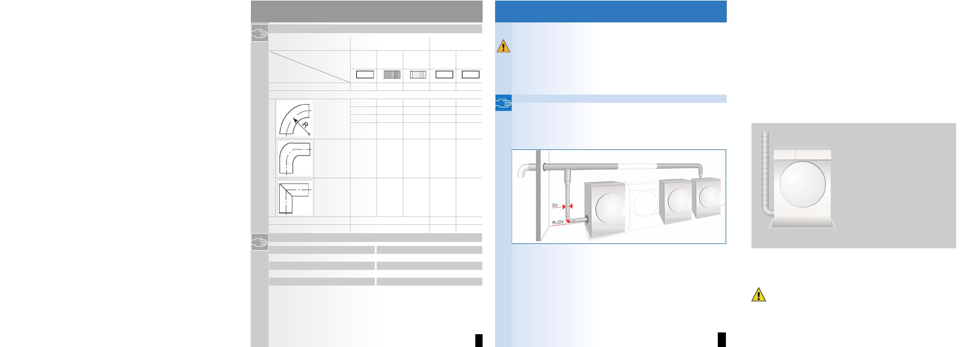
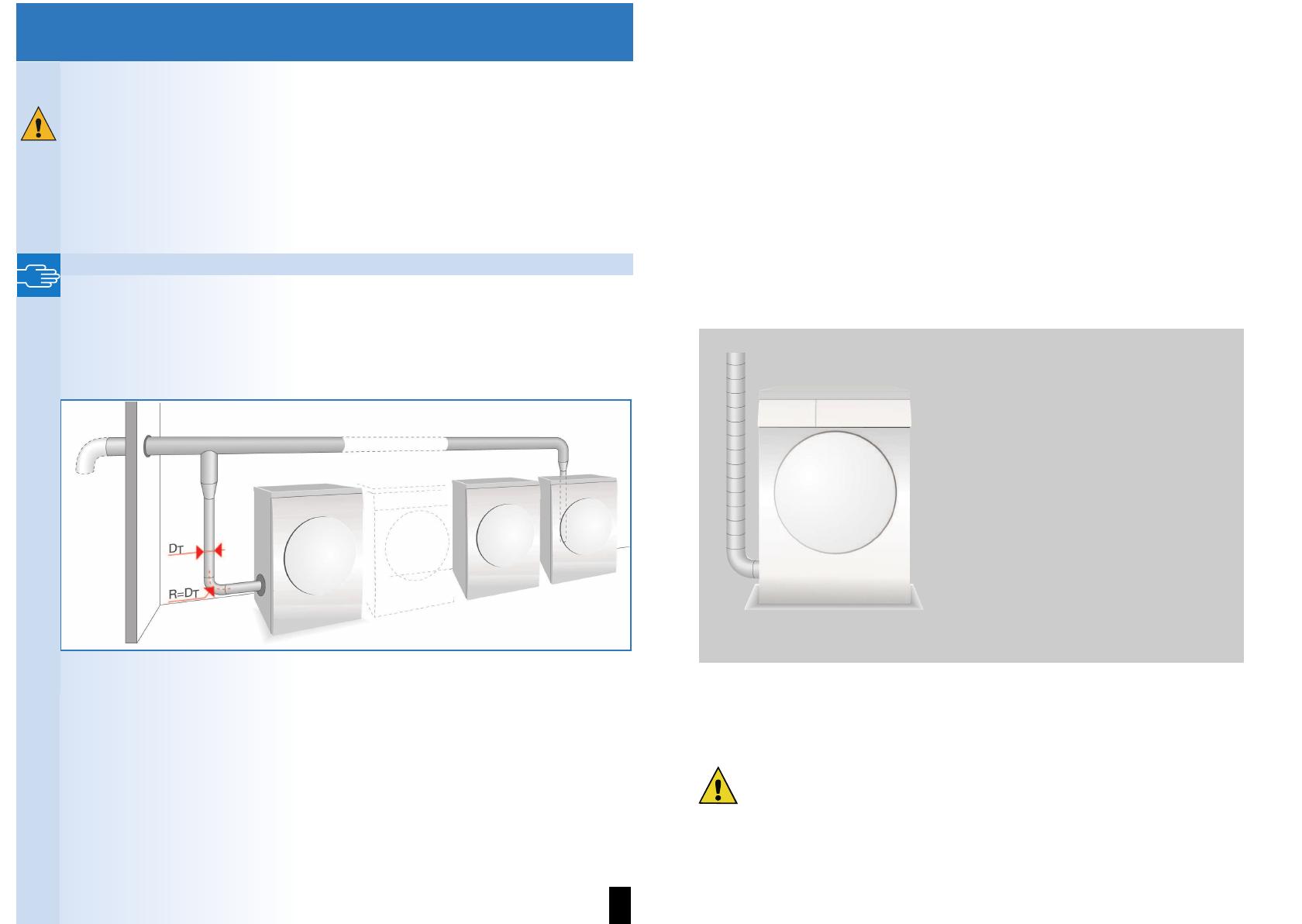
ʋ Installing more than one dryer ................................................................................................... 7
Safety instructions
– We recommend that you route the exhaust air directly into the open air through an exhaust
air duct.
– Where an exhaust air duct is routed to the open air, a drain check valve must be fitted
(prevents air from flowing back).
– Only install the air extraction system as described in these instructions.
– The air extraction system must not exceed the specified pressure losses, see page 3.
– Only use materials and parts specified in the instructions.
– Clean the exhaust air duct regularly, at least once a year.
When operating the dryer without an exhaust air duct, the following must also be observed:
– Ensure that the room is well ventilated, otherwise energy consumption and drying time will
increase.
– Ensure that the room is well ventilated a risk of damage caused by moisture, e.g. to walls,
furniture.
– Do not cover the exhaust air opening (leave approx. 1 m of free space around the exhaust
air opening).
2
Connections on the dryer
Connections for an exhaust air duct are located on the back panel and on the left side panel
of the dryer.
Back panel connection
The exhaust air opening on the back panel is open when the
dryer is delivered (bayonet ring).
The exhaust air opening on the left side panel is sealed with
a cover.
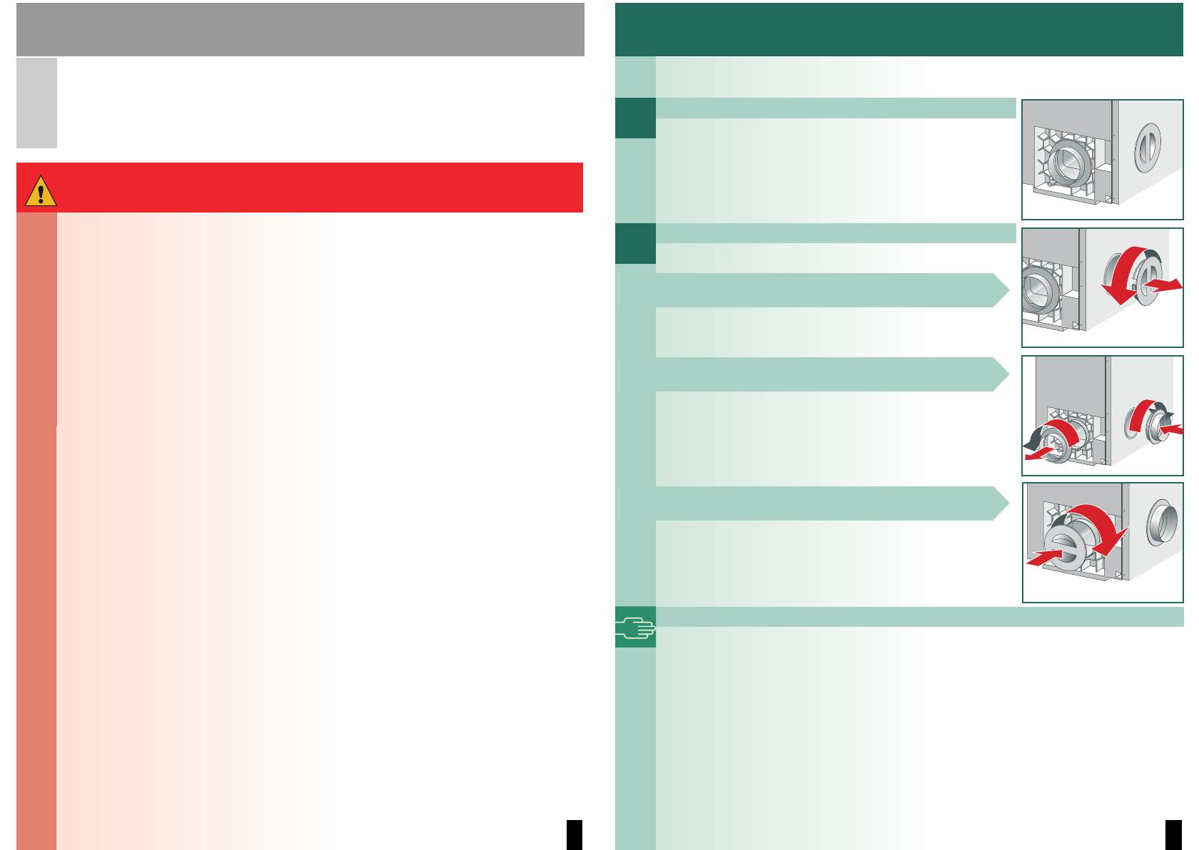
Left side panel connection
1. Remove the cover on the side panel.
2. Remove the bayonet ring from the back panel and attach it
to the opening on the side panel.
3. Seal the opening in the back panel with the cover.
Condensation outlet
If there is a high level of condensation in the exhaust air duct, it is advisable to fix a
condensation collector (standard) or a drain hole with a diameter of approximately 3 mm
to the lowest part of the exhaust air duct.
3
Notes on installation
Exhaust air duct
All standard products can be used for the exhaust air duct:
– flexible pipes
– galvanised metal ducts or pipes
– connectors, adapters, and diverters for flat duct systems and pipe systems
– wall boxes for evaporation into the open air or into a ventilation shaft
– adapters on rectangular ducts
– rectangular ducts or plastic pipes
– backpressure flap
The material must be heat resistant up to 80 °C and moisture resistant.
Pressure losses
The type and length of the exhaust air duct, particularly elbows or bends with small radii, can
impede the air flow. a Keep diameter reductions and pressure losses (resistance) to a
minimum.
The following must be avoided:
– long exhaust air ducts
– exhaust air ducts with small diameters
– exhaust air ducts with many bends and elbows.
Pressure losses through friction
Duct or pipe friction resistance, i.e. friction on the inside of the exhaust air duct, affects the
air flow as follows:
– the smoother the internal wall
– the larger the diameter of the internal wall
– the shorter the pipe
the lower the friction resistance.
Pressure losses due to fixtures
The exhaust air encounters further resistance through fixtures built into the pipe, e.g.
diverters (bends, elbows, angles), wall boxes with grids or backpressure flaps.
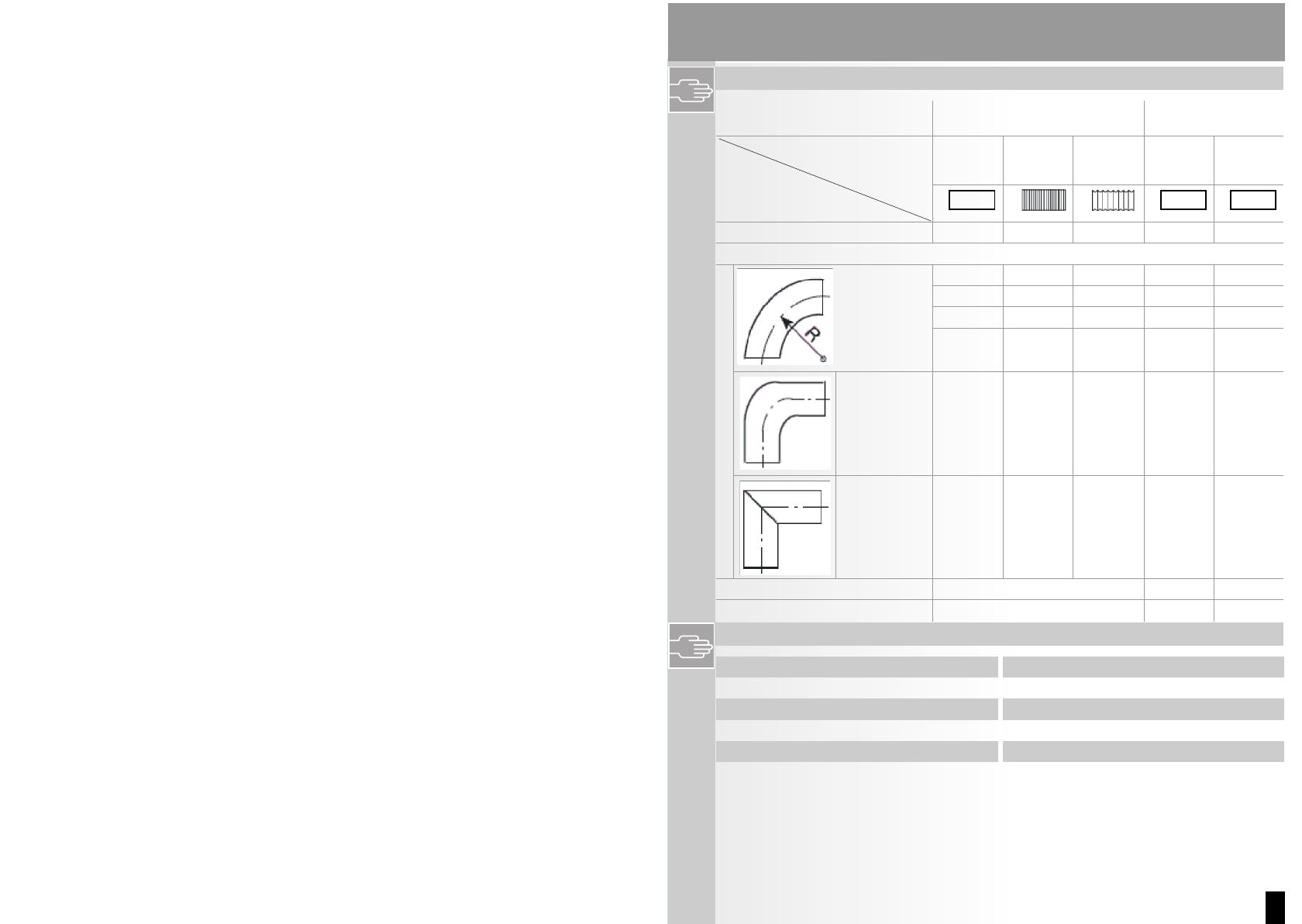
Installation for pipe connection - inside diameter = 100 mm
In order to ensure the minimum required air flow, a certain pressure loss (resistance) must
not be exceeded.
The permissible total pressure loss in an exhaust air duct must not exceed a certain value.
This is calculated as the sum of all individual pressure loss values for the straight pieces
and fixtures in the exhaust air duct.
The value for the maximum permissible total pressure loss for an exhaust air duct is 50*.
Installation for pipe connection - inside diameter = 100 mm
If the pipe connection has an inside diameter > 100 mm and a total pressure loss greater
than 50*, increase the inside diameter of the pipe connection
* To determine the total pressure loss see table a page 6.
4
Installation options
– Route the exhaust air duct in such a way that the dryer cannot draw the moist, warm
exhaust air back in again.
– The outlet for the exhaust air must be designed or positioned in such a way as to
prevent any additional backpressure (e.g. from a direct ingress of wind) on the
escaping exhaust air, e.g. by using a 90° bend, facing down a page 7.
– The outlet for the exhaust air duct must be no more than 2.5 m higher than the exhaust
air opening on the appliance.
Installation options for the exhaust air duct:
Through a wall box into the open air
Example: pipe connection - inside diameter = 100 mm,
smooth
A = straight piece (1.0 m) 4
B = curved pipe (R = 200 mm) 4
C = straight piece (1.5 m) 6
D = pipe elbow 19
E = telescopic wall box with grid 14
Total pressure loss 47
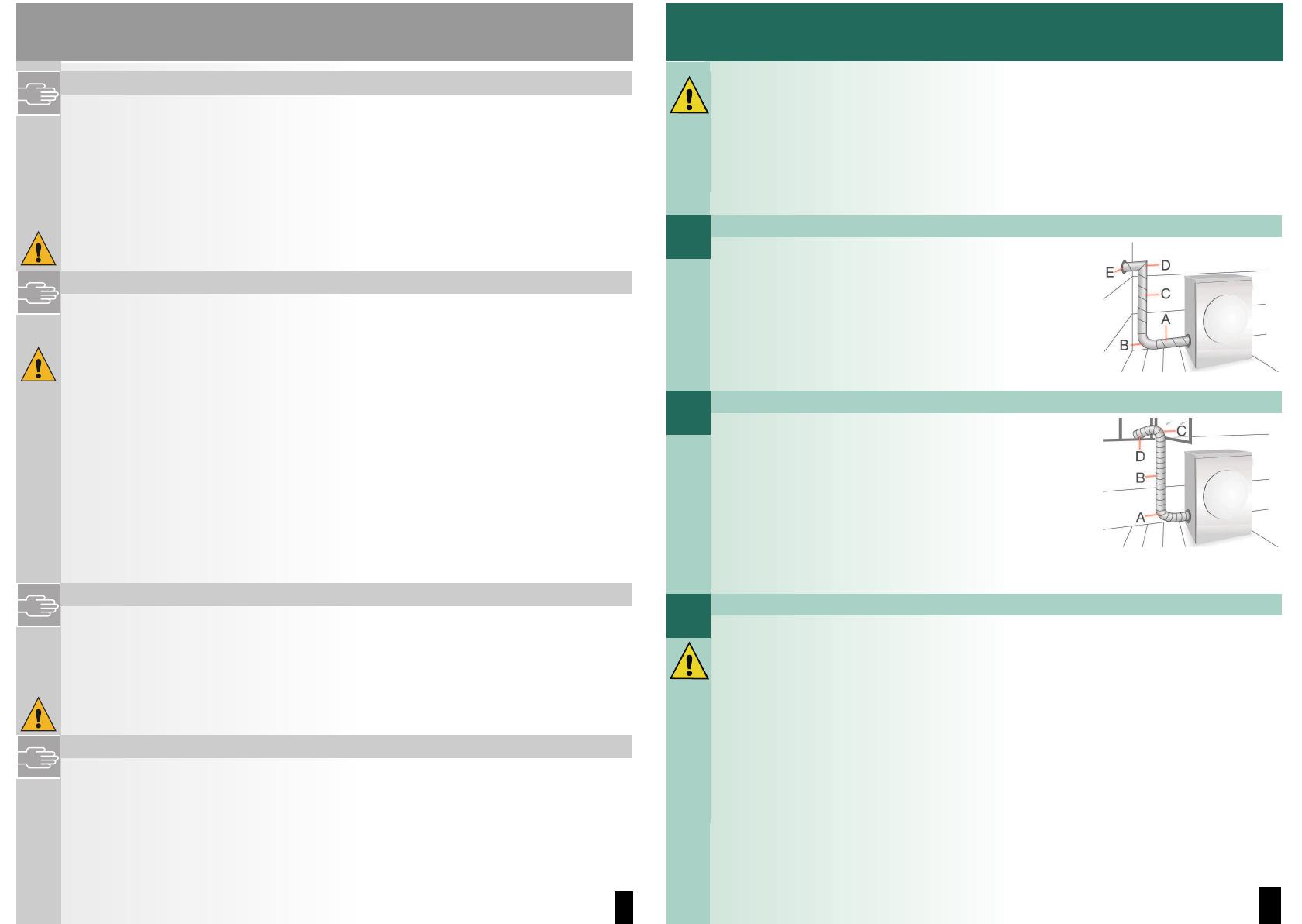
Directly into the open air
Route the exhaust air directly into the open air via an exhaust
air pipe through an open window.
Example:
Pipe connection - inside diameater = 100 mm, flexible pipe,
corrugated
A = curved pipe (R = 300 mm) 7
B = straight piece (1.5 m) 18
C = curved pipe (R = 100 mm) 10
D = straight piece (0.5 m) 6
Total pressure loss 41
Through a wall box into chimneys or ventilation shafts
– It is not permitted to connect the exhaust air duct to chimneys which are connected
to gas or coal-fired ovens/cookers or gas-fired heating systems.
– If the appliance is being connected to a moisture-insulated ventilation shaft the
responsible chimney sweep must be informed and the approval of the local building
department (building supervision office) or the owner of the building must be obtained.
– If other appliances are operated in the room where the appliance is installed or in
adjoining rooms, e.g. gas-fired heating systems, gas-fired boilers, coal-fired ovens
connected to a chimney, or open fireplaces, a vacuum may be created, leading to
waste gases being sucked back a risk of poisoning.
– In every case, have safe operation confirmed by the responsible chimney sweep, boiler
engineer, ventilation specialist, etc.