Introduction
Congratulations on your purchase of a Renkus-Heinz CF/CFX101LA series point source line array
loudspeaker system. Your CF/CFX series loudspeaker has been designed to provide you years of
trouble-free high performance listening pleasure. We hope you enjoy it.
Your CF/CFX101LA series loudspeaker was carefully tested and fully inspected before leaving our
factory and should have arrived in perfect condition. Please carefully inspect your loudspeaker and
its shipping carton for any noticeable damage and if any damage is found, immediately notify the
shipping company.
Only the consignee may institute a claim with the carrier for any damage incurred during shipping. Be
sure to save the carton and all packing materials for the carrier’s inspection.
Table of Contents
Introduction 2
Modular Point Source Line Arrays , An Overview 3
Ground Stacked & Pole Mounted Systems 4
Flying Arrays 5
Subwoofer Assembly 5
EASE Focus 6
CXF101LA Connections 6
CFX101LA-5 Connections 7
CF101LA-5R & CF101LA-52R Connections 8
High Frequency Control Settings 9
CFX101LA & CFX15S DSP Settings 10
TechnicalSpecications 12
Technical Support
If you run into any problems or have any questions about these products, please call our
technical support staff at +1 949 588 9997 and ask the operator for technical support
CallMondaythroughFridayfrom8:30AMto5:00PMPacictime.
MPSA Loudspeaker Systems
Page 2
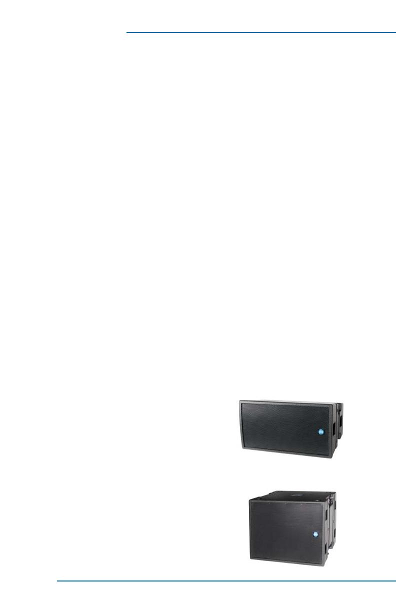
Modular Point Source Line Arrays
Designed for power, portability and versatility,
CF101LA and CFX101LA modular point source
line array systems from Renkus-Heinz are the
ideal solution for today’s small and mid-sized ven-
ues, including auditoriums, night clubs, theaters
and houses of worship.
Individual full range cabinets can be used as a
stand-alone system, either with or without an
associatedsubwoofer.Theycanbeownorpole
mounted on a matching subwoofer or standard
loudspeaker tripod stand.
CF101LA/CFX101LA Array Module
CF15S/CFX15S Subwoofer


