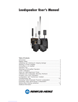
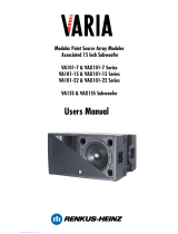
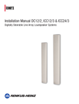
CF101LA-52R

Renkus-Heinz CF101LA-52R, CF101LA-5, CF101LA-5R, CF15S-5, CF15S-5R, CFX101LA, CFX101LA-8, CFX15S, CFX15S-8 User manual

  • Hello! I am an AI chatbot trained to assist you with the Renkus-Heinz CF101LA-52R User manual. I’ve already reviewed the document and can help you find the information you need or explain it in simple terms. Just ask your questions, and providing more details will help me assist you more effectively!
CFX101LA - CFX101LA-8
Externally Powered
CF101LA-5 - CF101LA-5R - CF101LA-52R
Self-Powered - RHAON Empowered
CFX15S - CFX15S-8
Externally Powered
CF15S-5 - CF15S-5R
Self-Powered - RHAON Empowered
Modular Point Source Arrays & Subwoofers
Users Manual
Introduction
Congratulations on your purchase of a Renkus-Heinz CF/CFX101LA series point source line array
loudspeaker system. Your CF/CFX series loudspeaker has been designed to provide you years of
trouble-free high performance listening pleasure. We hope you enjoy it.
Your CF/CFX101LA series loudspeaker was carefully tested and fully inspected before leaving our
factory and should have arrived in perfect condition. Please carefully inspect your loudspeaker and
its shipping carton for any noticeable damage and if any damage is found, immediately notify the
shipping company.
Only the consignee may institute a claim with the carrier for any damage incurred during shipping. Be
sure to save the carton and all packing materials for the carriers inspection.
Table of Contents
Introduction 2
Modular Point Source Line Arrays , An Overview 3
Ground Stacked & Pole Mounted Systems 4
Flying Arrays 5
Subwoofer Assembly 5
EASE Focus 6
CXF101LA Connections 6
CFX101LA-5 Connections 7
CF101LA-5R & CF101LA-52R Connections 8
High Frequency Control Settings 9
CFX101LA & CFX15S DSP Settings 10
TechnicalSpecications 12
Technical Support
If you run into any problems or have any questions about these products, please call our
technical support staff at +1 949 588 9997 and ask the operator for technical support
CallMondaythroughFridayfrom8:30AMto5:00PMPacictime.
MPSA Loudspeaker Systems
Page 2
Modular Point Source Line Arrays
Designed for power, portability and versatility,
CF101LA and CFX101LA modular point source
line array systems from Renkus-Heinz are the
ideal solution for today’s small and mid-sized ven-
ues, including auditoriums, night clubs, theaters
and houses of worship.
Individual full range cabinets can be used as a
stand-alone system, either with or without an
associatedsubwoofer.Theycanbeownorpole
mounted on a matching subwoofer or standard
loudspeaker tripod stand.
CF101LA/CFX101LA Array Module
CF15S/CFX15S Subwoofer
MPSA Loudspeaker Systems
Page 3
Modular Point Source Line Arrays (continued)
Suitedequallytoxedinstallationorportableapplica-
tions the full range array cabinets offer consistent 90
o
horizontal and tight 15
o
vertical coverage. Individual array
cabinets can be stacked or arrayed with each cabinet
increasing the vertical coverage by 15
o
degrees. Up to
four full-range modules can be arrayed to provide a 90
o
by 60
o
coverage pattern,.
Floor Mounted Systems
Each array cabinet is provided with a multi-angle 35 mm
pole socket that allows the cabinet’s output to be aimed up or
down or straight ahead.
The matching CF/CFX15S subwoofers are provided with a
threaded pole socket to assure reliability. The length of the as-
sociated POLE-CF101 is easily adjustable.
Toassemblethebasicoorsystemshownhere:
1. Screw the mounting pole into the threaded pole socket on the
subwoofer.
2. Place the array cabinet on top of the pole using the bottom
mounted tripod socket
3 Adjust the height and coverage angle as desired.
If a second array module is needed:
1. Place the secondmoduleontopoftherstmoduleandalign
the metal hardware channels.
2. Remove the quick disconnect pins on the top array module
and use the knurled knobs on the joining bars to slide them down
into the channels on the lower cabinet. (See Step 2 below)
3. Then lock the cabinets together by inserting the quick disconnect pins into the metal channels on
the lower cabinet. (See Step 3 below).
If two subwoofers are used follow the same procedure used for the array modules; set one on top of
the other, align, remove quick disconnect pins on the top subwoofer, slide the joining bars down and
lock in place with the quick disconnect pins.
Pole mounted arrays should be limited to two CF/CFX101LA mounted on either one or two subwoof-
ers.
Multi Angle Pole Socket POLE-CF101 Pole
Floor System;
single array module and subwoofer
Step 3
Step 2
Floor Mounted Systems (continued)
Ground Stacks
Point source line array modules and their matching subwoofers
can also be ground stacked using the subwoofers as a mounting
base for the array modules.
Ground stacks can include as many as 3 array modules plus one
or two matching subwoofers.
Safety considerations are always a factor in any venue and
consideration must be given to the strength and stability of the
surface / platform on which the ground stack will be placed.
To assemble a ground stack;
1. Place the subwoofer that will be used as the base into posi-
tion.
2. Place the next cabinet into position on top of the subwoofer and align the connecting hardware
channels.
3. If the second cabinet is another subwoofer remove the quick disconnect pins from the top
subwoofer and use the knurled knobs to move the joining bars from the top subwoofer down into the
lower subwoofer.
If the second cabinet is an array module remove the upper quick disconnect pins from the sub-
woofer’s joining channels and use the knurled knobs to move the joining bars up from the subwoofer
into the array module.
NOTE: The rule on joining bars is that when joining like cabinets (two array module modules
or two subwoofers), move the joining bars from the top cabinet down into the lower cabinet,
When joining a subwoofer and array module move the subwoofers joining bars into the array
module.
Flying Arrays
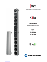
CF101LA and CFX101LA arrays suspend from a ceiling or truss as easily as they ground stack.
The subwoofers which were used as a mounting base for the ar-
ray cabinets in ground stacked arrays now becomes the suspen-
sion platform for the array and are placed at the top of the array.
Refer to array photo at the top of the next page.
The Subwoofers are equipped with rubberfeetthattinto
matching cups in the top of the lower subwoofer when two units
arestackedtogether.Asaresultwhenthesubwoofersareown
in an array such as the one shown above, the subwoofer has to
turned upside down. Otherwise the feet prevent the subwoofer and array module from being joined
together.
MPSA Loudspeaker Systems
Page 4
Ground Stack
with 2 array modules,1 subwoofer
CF15S/CFX15S Subwoofer
Flying Arrays (continued)
Theprocedureforassemblingarraysthatwillbeownis
similar to the one used to assemble ground stacks, except
that the order is reversed. Ground stacks are assembled from
thebottomupwhileownarraysareusuallyassembledfrom
the top down.
TypicallytheRHANG101LAFlybarisusedtoyanarray
in both portable applications and permanent installations.
The cabinets built in attachment points are used mainly in
permanent installations.
Toassembleaownarray:
1. Attach the RHANG101LA Flybar to the top cabinet using
the quick release pins. Note the bridle construction which
allows you to move the suspension bar laterally and adjust
the array’s tilt (aiming angle). Move the bridle toward the rear
of the cabinets for more tilt.
2. Attach the lifting device (chain hoist, fork lift, etc) you will use
toraisethecabinetintopositiontotheybar.Onecommonly
used arrangement is shackles and a sling.
3 Raise the cabinet high enough to let you roll or slide the next
cabinet into position beneath it.
4. Lower the cabinet into position onto the second cabinet and
use the quick release pins and joining bars to lock the two
cabinets together. Move the joining bars from the upper cabinet
down into the lower cabinet.
5. Repeat the procedure until the array is complete and then lift (hoist) the array into position and
secure it.
The heavy duty RHANG101LA Flybar supports arrays of up to 6 cabinets (4 array modules and 2
subwoofers). Arrays with 3 array modules provide 45
o
vertical coverage and 4 module arrays 60
o
.
Horizontal coverage remains constant at 90
o
.
MPSA Loudspeaker Systems
Page 5
Adjustable Bridle
with quick disconnect pins
Rigging Points (3 provided)
EASE FOCUS allows you to quickly and accurately determine the size of the array needed to cover
the audience and its proper location and aiming angle.
EASE FOCUS
Important Mounting Instructions
To ensure proper air movement for the cooling of self-powered loudspeakers, we recommend a
minimum of 2 to 3 feet of clearance in front of the loudspeaker and at least 6 inches of clearance
from the sides and the rear cabinet surfaces.
Warning:
The actual rigging of loudspeakers suspended from a truss or from a ceiling is a serious
undertaking that is beyond the scope of this document. It should be done only by qualied
and experienced professionals using only load rated hardware.
We strongly recommend that you have your design reviewed and approved by a licensed
structural engineer who can also verify the suitability of the building attachment points.
Renkus-Heinz is not responsible for any non Renkus-Heinz products or for any misuse of
Renkus-Heinz products.
MPSA Loudspeaker Systems
Page 6
MPSA Loudspeaker Systems
Page 7
Your CFX101LA loudspeaker was shipped to you wired for fully passive operation using the internal crossover.
Itcanbeconvertedtobi-ampliedoperationbyremovingtheconnectorplatefromthecabinetandchanging
several internal connections. For detailed instructions, please refer to the Renkus-Heinz Loudspeaker User’s
manual, form RH508.
CFX101LA AND CF 101LA Connections
Screw Terminal Strip
Inputs
Looping In & Out
Neutrik 4-Pin Speakon Connectors
Signal & Limiting
LED Status
Indicators
Looping In & Out
(female in -
male out)
XLR Type
Connectors
110 V or 230 V
50/60 Hz AC
Input Voltage
Selector
Screwdriver
Adjustable
Gain Control
Power On/Off
Switch
IEC Power Connector & Fuse
CF101LA-5R & C F101LA-52R RHAON Empowered Array Module Connections
TheinputpanelshownbelowisforthePF2-500Rdigitalbi-amplierusedintheCF101LA-52R
TheinputpanelofthePF1-500RamplierusedintheCF101LA-5Risidentical,exceptforhaving
only a single Mute button. For more detailed information, please refer to the Renkus-Heinz RHAON
User’s Manual.
AC Line Voltage
Selector
AC Line Fuse
IEC Power
Connector
AC Power On/Off
Primary Analog Input
XLR female
Looping Analog
Output
XLR male
Signal & Overdrive
LED Status Indicators
Input Pad &
LED Indicator
Push Button
Volume Controls
Mute Buttons
Primary & Secondary
Ethernet (CobraNet) Inputs
RJ-45 female
Secondary Analog
Input & Looping Output
Serial Digital Audio Input
Fault Detect
Fault Relay
Power LED Thermal LED
MPSA Loudspeaker Systems
Page 8
MPSA Loudspeaker Systems
Page 9
High Frequency Control Settings
Not all setups are identical and neither
are all rooms. The high frequency level
controls on the rear of each CF101LA
and CFX101LA point source array
module allow you to adjust the high
frequency output of each module to
compensate for the increased loss of
high frequency energy from air loss over
distance, for increased coupling between
array modules at low frequencies and for
varying room sizes and acoustics. They
allow you to maintain the proper High/
Mid/Low frequency balance throughout
the listening area.
The control settings shown below are provided as guide lines to assist you in setup. They are not
“hard and fast” settings that apply to every setup as no two setups are alike.
Set controls to Flat
Set all controls to + 6 dB
Set all controls to + 9 dB
AMP GAIN FOR 1PC CFX101LA0 dB
AMP GAIN FOR 2PCS CFX101LA +6 dB
AMP GAIN FOR 3PCS CFX101LA +9 dB
OUTPUT DELAYNONE
POLARITY NORMAL
CROSSOVER
CENTER FREQUENCY120 Hz LP
TYPE BUTTERWORTH
SLOPE12 dB/ Oct
EQ #1
CENTER FREQUENCYNONE
BW NONE
BOOST/CUTNONE
EQ #2
CENTER FREQUENCYNONE
BW NONE
BOOST/CUTNONE
EQ #3
CENTER FREQUENCYNONE
BW NONE
BOOST/CUTNONE
BUTTERWORTH
24 dB/ Oct
NORMAL
0 dB
CFX101LA-8 WIRED AS PASSIVE
50 Hz HP
0 dB
ITEM
CFX15S-8 WIRED AS PASSIVE
1.5 kHz
1.50
8.5 kHz
0.4
+6 dB
16.0 kHz
*
**
* When the CFX101LA is being used with a CFX15S-8 subwoofer, delay the CFX101LA 2.7 ms.
** Do not bypass the passive crossover in the CFX15S-8, even when an external electronic crossover is used.
CFX101LA & CFX15S DSP Settings
Suggested DSP settings for various CFX101LA line array modules and CFX15S
subwoofer combinations appear below and on the next page.
Note that these would not apply to the CF101LA-5R and CF101LA-52R which include built-in DSP.
MPSA Loudspeaker Systems
Page 10
MPSA Loudspeaker Systems
Page 11
HF
AMP GAIN FOR 1PC CFX101LA -18 dB
AMP GAIN FOR 2PCS CFX101LA -12 dB
AMP GAIN FOR 3PCS CFX101LA -9 dB
OUTPUT DELA
YN
ONE
POLARITY NORMAL
CROSSOVER
CENTER FREQUENCY50 Hz HP 1.6 kHz LP 1.7 kHz HP 40 Hz HP 80 Hz LP
TYPEBUTTERWORTHLINKWITZ-RILEYLINKWITZ-RILEYBUTTERWORTH BUTTERWORTH
SLOPE24 dB/ Oct24 dB/ Oct24 dB/ Oct 24 dB/ Oct 18 dB/ Oct
EQ #1
CENTER FREQUENCY2.3 kHz
BW .35
BOOST/CU
T-
4 dB
EQ #2
CENTER FREQUENC
Y3
.3 kHz
BW .35
BOOST/CU
T-
4 dB
EQ #3
CENTER FREQUENCY 12 kHz
BW .3
BOOST/CU
T+
6 dB
EQ #4
CENTER FREQUENCY 16 kHz
BW .5
BOOST/CU
T+
9 dB
NONE
NONENONE
NONE
NONE NONE
NONE
240 Hz
NONE NONE
NONE NONE
-3.0 dB NONE
570 Hz NONE
CFX15S-8 WIRED AS ACTIVE**
NONE
0.4 NONE
-3.0 dB NONE
0.4 NONE
0.530mS NONE
NORMAL INVERTED
0 dB +9 dB
NONE
0 dB 0 dB
0 dB +6 dB
CFX101LA-8 WIRED AS BI-AMP *
LF
ITEM
* When the CFX101LA is being used with a CFX15S-8 subwoofer, delay the CFX101LA 2.17 ms.
** When the CFX15S-8 is used in this fashion, its passive crossover needs to be bypassed.
CFX101LA & CFX15S DSP Settings (Continued)
Sensitivity
CF101LA:
CFX101LA-8:
Max SPL:
Dispersion:
Freq. Resp:
HF Drivers:
LF Driver:
Crossover:
Enclosure:
Power
CF101LA:
CFX101LA-8:
Finish:
Hardware:
Dimensions:
Weight
CF101LA-5 & -5R:
CF101LA-52R:
CFX101LA-8:
1.0 V for rated power output
96 dB (1W/1m)
127 dB peak
90
O
Horizontal,15
O
Vertical
60 Hz to 20 kHz
Two 1” SSDCDXI-1730-8 HF
Neodymium drivers;
75 W RMS @ 8 Ohms,
150 W pgm each
CF101LA 10” SSL10-10,
Neodymium woofer,
250 W RMS @ 4 Ohms,
500 W pgm
CFX101LA-8: 10” SSL10-8,
250 W RMS @ 8 Ohm,
500 W pgm
1700 Hz
Multi-ply hardwood,
perforated metal grille
115 V AC or 230 V AC
50/60 Hz
500 W pgm at 8 Ohms
Black or white,
custom color optional
Four M10 attachment points
Multi-angle pole socket
Integralyinghardware
13” H x 23 3/4” W x 15” D
(33 cm x 60.3 cm x 38.1cm)
56 Lbs. (25.4 Kg) net
58 Lbs (26.3 Kg) net
54 Lbs (24.5 Kg) net
Sensitivity
CF15S-5 & -5R:
CFX15S-8:
Max SPL
CF15S-5 & -5R:
CFX15S-8:
Freq. Resp:
LF Driver:
Enclosure:
Finish:
Power
CF15S-5 & -5R:
CFX15S:
CFX15S-8:
Hardware:
Dimensions:
Weight
CF15S-5 & -5R:
CFX15S:
Associated Items:
1.0 V for RPO
97 dB (1W/1m)
127 dB peak
129 dB peak
40 Hz to 120 Hz
CF15S: SSL15-20
15” Neodymium woofer,
400 W RMS @ 4 Ohms,
800 W pgm
CFX15S-8: SSL15-17,
15” Neodymium woofer
400 W RMS @ 8 Ohms,
800 W pgm
13-ply hardwood,
perforated metal grille
Black or white;
custom color optional
115 V AC or 230V AC
800 W pgm at 8 Ohms
8-point univ. mtg. hdw.
(Metric M10 threads)
Threaded pole socket,
Integralyinghardware
Optional - heavy duty wheels
19” H x 23 3/4” W x 22 1/2” D
(48.3 cm x 60.3 cm x 56.5 cm)
114 Lbs (51.7 Kg) net
112 Lbs (50.8 Kg) net
RHANG101LA Flybar
POLE-CF101 Mounting Pole
Renkus-Heinz, Inc., 19201 Cook Street, Foothill Ranch, CA 92610-3501, USA
Tel:+1949-588-9997•Fax:+1949-588-9514•[email protected]•www.renkus-heinz.com
CF/CFX101-LA
CF/CFX15S
RH 723 rev D November 2011
Technical Specications
/