Page is loading ...

MANUAL
• Specifications...................………………………..
2
• Installation, Start-Up, Operating Instructions
2
• Cleaning…………………………………………….
3
• Adjustments & Troubleshooting……………….
4
• Parts Identification..............……………………...
5
• Wiring Diagrams …...............……………………. 7
NL72A
APT18P
POUROVER COFFEE BREWER
Cecilware sells value... Worldwide
43 -05 20th Avenue, Long Island City, NY 11105
TEL • 718-932-1414
FAX • 718-932-7860

2
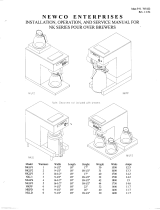
SPECIFICATIONS
MODEL VOLTS TOTAL KW AMPS W D H
C-2001P 120 1.6 15 8.00 17.35 17.25
WARNING: MACHINE WARRANTY IS VOID IF MACHINE IS CONNECTED TO ANY VOLTAGE
OTHER THAN 120 VOLTS. (EXPORT UNITS SHOULD BE CONNECTED TO 220 VOLTS)
** INSTALLATION INSTRUCTIONS **
NOTE: a separate circuit should be supplied for each of these brewers with a 15 amp
circuit breaker or fuse. Check local codes for compliance in installation.
MANUAL POUROVER MODELS - Are not equipped with water inlet connections.
CAUTION:
DO NOT CONNECT TO POWER SOURCE UNTIL AFTER PRIMING.
These brewers are equipped with a rear Toggle Switch which controls the power to the tank
heater. Toggle Switch must be in the down or “OFF” position until step (3) is completed.
** PRIMING INSTRUCTIONS - MANUAL POUROVER UNITS **
THESE INSTRUCTIONS ARE FOR INITIAL PRIMING ONLY AND DO NOT HAVE TO BE REPEATED
FOR NORMAL OPERATION.
1. Remove sample filter pack from Brew Funnel and insert Brew Funnel back into machine.
2. Place an empty Air Pot directly under brew funnel.
3. Lift pourover cover and pour 2 liters or approximately ½ gal. (one Air Pot or one Decanter) of
cold water through the top opening at 3 minute intervals. After the third Decanter is poured, water
will flow through the spray head and funnel and fill the Air Pot beneath.
4. Plug line cord into receptacle and turn “ON” (TOGGLE UP) the Heater Switch, which is located
in the back, then turn on the Power Switch which is located on the front panel. The Power Switch
Light will light, indicating power is being applied to the machine. Wait approximately 15 minutes
for the water to reach brewing temperature, at which point the green light comes on. You are
ready to brew coffee.
** BREWING INSTRUCTIONS - MANUAL POUROVER UNITS **
After initial priming has been completed
1. Insert Brew Funnel with filter and grounds into machine.
2. Place an empty Air Pot directly under Brew Funnel.
3. Lift pourover cover and pour 2 liters or approximately ½ gal. (one Air Pot or one Decanter) of
cold water through the top opening, coffee will be ready in 3 ½ minutes.
4. Remove grounds and filter as soon as coffee has dripped through. Never pour coffee back
through spent grounds.

3
** CLEANING INSTRUCTIONS **
1. Wash Brew Funnel and Air Pot by hand as needed. Do not use dishwasher, which may cause
Air Pot breakage.
2. For cleaning all metal surfaces, use any reputable stainless steel cleaning compound.
Spray head should be checked and cleaned regularly. (At least once a week.) Spray head holes
must be kept open.
To prevent “LIMING” problems in the water tube, remove spray head and insert spring probe all
the way into the tank through the tube. When inserted into tank properly, no more than two inches
of spring should be visible. Push back and forth five or six times. This will keep tubes open and
clear of lime. In hard water areas, this should be done every day; this takes less than a minute.
SANITIZING:
All food dispensing units should be sanitized periodically. All parts to be sanitized must be
cleaned first.
To prepare a sanitizing solution: ADD 2 TSP. OF LIQUID CLOROX BLEACH (5.25%
CONCENTRATION) TO 1 GALLON OF WATER AT ROOM TEMPERATURE (70° - 90°F).
Soak all parts for a minimum of 3 min. in the sanitizing solution.
Note: Always start with an unopened bottle of Clorox Bleach since the solution from an opened
bottle has a short life span.
Let all sanitized parts drain and dry naturally. DO NOT WIPE THEM DRY.
Before using the sanitized unit (or parts) with food stuffs, rinse all parts thoroughly with water.
CARE FOR STAINLESS STEEL: Stainless Steel surfaces that come in contact with food
substances, MUST BE CLEANED EVERY BDAY. WHEN CLEANING STAINLESS STEEL,
ONLY A pH NEUTRAL CLEANER IS TO BE USED.
Use nylon or brass brushes (not steel wire brushes) for removing food deposit.
Many food products contain acids, alkalies, or other substances which corrode Stainless Steel.

4
**SERVICE INSTRUCTIONS** and **TROUBLE SHOOTING GUIDE**
FOR AUTHORIZED SERVICE PERSONNEL ONLY
CAUTION: DISCONNECT POWER BEFORE ATTEMPTING ANY ELECTRICAL REPAIRS.
THERMOSTAT ADJUSTMENTS:
NOTE:
The thermostat is behind the lower front panel. If water temperature is less than 197 degrees F
(92 degrees C) slowly turn thermostat knob clockwise until ready light goes out. When temperature of water
approaches 197 degrees to 203 degrees F (92 degrees to 95 degrees C) slowly turn thermostat knob
counterclockwise until the green ready light comes on. If water temperature cannot be increased when
thermostat knob is turned fully clockwise, then proceed as follows:
Pull off knob. Place a small screwdriver into the center of thermostat shaft. While observing green ready
light and temperature on thermometer, hold shaft and turn small adjustment screw in center counter-
clockwise until green ready light goes out. When temperature of water approaches 197 degrees - 203
degrees F (92 degrees - 95 degrees C), slowly turn screw clockwise until ready light comes on. Turning
screw clockwise lowers temperature; counter-clockwise raises it. After adjusting center screw, place nail
polish or glyptol on screw to set in position.
NOTE:
As a final check, measure water temperature at Spray Head . Temperature should be 197 degrees
to 203 degrees F (92 degrees to 95 degrees C).
IF WATER FAILS TO HEAT:
1. If Red power switch does not light, check heater switch in the back, toggle should be in the up position .
Check power supply outlet, replace fuse or reset circuit breaker if necessary. If power is good, check rear
heater switch for continuity and replace if switch stays open.
2. If water still fails to heat, disconnect line cord and check out tank heater, thermostat and high
temperature safety shutoff. Replace needed parts.
REPLACING HI-LIMIT SWITCH, THERMOSTAT, AND TANK HEATER
Unplug power cord, and remove top cover and lower front cover.
HI-LIMIT SWITCH
Disconnect the (2) push-on leads, and pull out hi-limit. Replace switch.
THERMOSTAT
Loosen (2) screws securing thermostat to housing. Disconnect the push-on leads and
remove thermostat. Replace with new one in reverse order. When installing new control, do not overtighten
small packing nut on compression fitting.
TANK HEATER
Remove tank top, (4) hex nuts and washers. Disconnect push-on leads. Replace in
reverse order. Remove the lower panel and loosen the (2) screws holding thermostat in place. Slide
thermostat out of bracket and remove wires. Remove top cover and pull out Capillary Tank fitting from
silicone grommet.

5
** PARTS IDENTIFICATION **
ITEM PART
NUMBER
DESCRIPTION
1 SO91Q BODY FRAME ASSEMBLY
2 SI64A FRONT TOWER COVER
3 V223A AIR POT, 2.2 liters (NOT INCLUDED WITH BREWER)
4 L217A POWER SWITCH, RED, ROCKER
5 C072A READY LIGHT, GREEN
6 NL68A LABEL
7 V000A BREW FUNNEL, BLACK
8 L069A
U810C
HEATER SWITCH
SWITCH GUARD
9 C032A ELECTRICAL CORD
10 U588C COVER, POUROVER - ROUND
11 U587C POUR OVER DISH
1
3
7
4
5
6
8
9
10
11
2

6
FRONT VIEW – OPEN TOP VIEW - OPEN
ITEM PART NUMBER DESCRIPTION
1 L681A THERMOSTAT ASS’Y
2 B171A TERMINAL BLOCK
3 RK48Q TANK ASS’Y
4 K525A SS ELBOW TUBE (2)
5 M611A SILICONE TUBE, .5 ID, WATER INLET & DRAIN
6 L069A HEATER SWITCH
7 RQ74A TANK TOP
8 G296A HEATER ELEMENT 120V, 1500 W
9 L573A HI LIMIT, 220 CUTOFF
10 H297Q SPRAY TUBE ASS’Y
11 UB28A SPRAY HEAD HOUSING
12 RP97Q TROUGH SUB-ASS’Y
1
2
4
3
5
6
8
9
5
12
11
10
7
1

7
/