Page is loading ...

EIO0000001539.00
www.schneider-electric.com
Zelio Control
EIO0000001539 04/2013
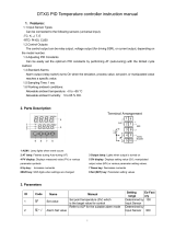
Zelio Control
RTC48 Temperature Controller
User Guide
04/2013

2 EIO0000001539 04/2013
The information provided in this documentation contains general descriptions and/or
technical characteristics of the performance of the products contained herein. This
documentation is not intended as a substitute for and is not to be used for
determining suitability or reliability of these products for specific user applications. It
is the duty of any such user or integrator to perform the appropriate and complete
risk analysis, evaluation and testing of the products with respect to the relevant
specific application or use thereof. Neither Schneider Electric nor any of its affiliates
or subsidiaries shall be responsible or liable for misuse of the information that is
contained herein. If you have any suggestions for improvements or amendments or
have found errors in this publication, please notify us.
No part of this document may be reproduced in any form or by any means, electronic
or mechanical, including photocopying, without express written permission of
Schneider Electric.
All pertinent state, regional, and local safety regulations must be observed when
installing and using this product. For reasons of safety and to help ensure
compliance with documented system data, only the manufacturer should perform
repairs to components.
When devices are used for applications with technical safety requirements, the
relevant instructions must be followed.
Failure to use Schneider Electric software or approved software with our hardware
products may result in injury, harm, or improper operating results.
Failure to observe this information can result in injury or equipment damage.
© 2013 Schneider Electric. All rights reserved.

EIO0000001539 04/2013 3
Table of Contents
Safety Information . . . . . . . . . . . . . . . . . . . . . . . . . . . . . . 5
About the Book . . . . . . . . . . . . . . . . . . . . . . . . . . . . . . . . . 7
Part I RTC48 Temperature Controller . . . . . . . . . . . . . . . . . 9
Chapter 1 Introduction. . . . . . . . . . . . . . . . . . . . . . . . . . . . . . . . . . . . 11
Display and Controller References of RTC48 . . . . . . . . . . . . . . . . . . . . . . 12
Main Specifications . . . . . . . . . . . . . . . . . . . . . . . . . . . . . . . . . . . . . . . . . . 15
Chapter 2 Hardware of RTC48. . . . . . . . . . . . . . . . . . . . . . . . . . . . . . 17
Electrical and Environmental Characteristics . . . . . . . . . . . . . . . . . . . . . . 18
Dimensions and Installation of RTC48 . . . . . . . . . . . . . . . . . . . . . . . . . . . 20
Wiring of RTC48 . . . . . . . . . . . . . . . . . . . . . . . . . . . . . . . . . . . . . . . . . . . . 24
Chapter 3 Configuration of RTC48 . . . . . . . . . . . . . . . . . . . . . . . . . . 29
How to Configure Using Front Panel. . . . . . . . . . . . . . . . . . . . . . . . . . . . . 30
Basic Operations. . . . . . . . . . . . . . . . . . . . . . . . . . . . . . . . . . . . . . . . . . . . 31
Lock. . . . . . . . . . . . . . . . . . . . . . . . . . . . . . . . . . . . . . . . . . . . . . . . . . . . . . 32
Setting the Temperature Controller. . . . . . . . . . . . . . . . . . . . . . . . . . . . . . 33
Operation Flowchart . . . . . . . . . . . . . . . . . . . . . . . . . . . . . . . . . . . . . . . . . 37
Parameters List . . . . . . . . . . . . . . . . . . . . . . . . . . . . . . . . . . . . . . . . . . . . . 40
Chapter 4 Main Functions of RTC48. . . . . . . . . . . . . . . . . . . . . . . . . 53
Auto-Tuning. . . . . . . . . . . . . . . . . . . . . . . . . . . . . . . . . . . . . . . . . . . . . . . . 54
Control Actions . . . . . . . . . . . . . . . . . . . . . . . . . . . . . . . . . . . . . . . . . . . . . 57
Alarm Functions . . . . . . . . . . . . . . . . . . . . . . . . . . . . . . . . . . . . . . . . . . . . 58
PV Color Display Function . . . . . . . . . . . . . . . . . . . . . . . . . . . . . . . . . . . . 60
OUT1 Rate of Change. . . . . . . . . . . . . . . . . . . . . . . . . . . . . . . . . . . . . . . . 62
Part II Appendices . . . . . . . . . . . . . . . . . . . . . . . . . . . . . . . . . 63
Chapter 5 RTC48 Error Messages . . . . . . . . . . . . . . . . . . . . . . . . . . 65
Troubleshooting. . . . . . . . . . . . . . . . . . . . . . . . . . . . . . . . . . . . . . . . . . . . . 65
Index . . . . . . . . . . . . . . . . . . . . . . . . . . . . . . . . . . . . . . . . . . . 69

4 EIO0000001539 04/2013

EIO0000001539 04/2013 5
§
Safety Information
Important Information
NOTICE
Read these instructions carefully, and look at the equipment to become familiar with
the device before trying to install, operate, or maintain it. The following special
messages may appear throughout this documentation or on the equipment to warn
of potential hazards or to call attention to information that clarifies or simplifies a
procedure.

6 EIO0000001539 04/2013
PLEASE NOTE
Electrical equipment should be installed, operated, serviced, and maintained only by
qualified personnel. No responsibility is assumed by Schneider Electric for any
consequences arising out of the use of this material.
A qualified person is one who has skills and knowledge related to the construction
and operation of electrical equipment and its installation, and has received safety
training to recognize and avoid the hazards involved.

EIO0000001539 04/2013 7
About the Book
At a Glance
Document Scope
This guide describes the RTC48 temperature controller.
It provides the following of the RTC48 temperature controller:
Main characteristics,
Installation,
Wiring,
Configuration,
Main functions, and so on.
Validity Note
This document is valid for the RTC48 temperature controller.
Registered Trademarks
Microsoft® and Windows® are registered trademarks of Microsoft Corporation.

8 EIO0000001539 04/2013
Related Documents
You can download these technical publications and other technical information from
our website at www.schneider-electric.com.
User Comments
We welcome your comments about this document. You can reach us by e-mail at
Title of Documentation Reference Number
RTC48 Temperature Controller Quick Start Guide HRB3156801 (Eng)
HRB7904900 (Fre)
HRB7905100 (Chs)
HRB7905200 (Ger)
HRB7905400 (Ita)
HRB7905600 (Spa)
RTC48 Communication and Zelio Temperature Control Soft User
Guide
EIO0000001545 (Eng)
EIO0000001546 (Fre)
EIO0000001547 (Gre)
EIO0000001548 (Spa)
EIO0000001549 (Ita)
EIO0000001550 (Chs)


RTC48 Temperature Controller
10
EIO0000001539 04/2013


Introduction
12
EIO0000001539 04/2013
Display and Controller References of RTC48
Display of RTC48
The RTC48 is the temperature controller. It can be used in stand-alone installation
for simple machine or more complex system in association with programmable logic
controller (PLC), Human Machine Interface (HMI) through communication Modbus
(RS485).
The front panel has the Process Value (PV) and Setpoint Value (SV) displays and
indicators, the action indicators, and the setting keys.
Item Name Function
1 PV indicator Lights when Process Values (PV) are indicated in the
PV/SV display mode.
2 PV display Indicates the PV or displays the name of the parameters
during the setting mode.
3 SV indicator Lights when Setting Values (SV) are indicated in the
PV/SV display mode.
4 SV display Indicates the SV, Manipulated Variable (MV), or each set
value during the setting mode.
5 Action indicators O1 (OUT1): Lights when control output (OUT1) is ON.
O2 (OUT2): Lights when control output (OUT2) (when
OUT2 model applicable) is ON.
EV1: Lights when Alarm 1 output is ON.
EV2: Lights when Alarm 2 output is ON (when Alarm 2
model is applicable).
AT: Flashes while auto-tuning (AT) or auto-reset is
performing.
T/R: Lights during serial communication (when
communication model is applicable).
LOCK: Lights when Lock 1, Lock 2, or Lock 3 is selected.
6 Increase key Increases the numeric value.
O1
SV
PV
O2
EV1
EV2
AT
T/R
LOCK
1
2
5
8
9
3
4
6
10
7

Introduction
EIO0000001539 04/2013 13
Controller References and Characteristics
This table shows the controller references with the characteristics of each:
7 Decrease key Decreases the numeric value.
8 Page key Selects the setting mode or registers the setting value.
To register the SV, press this key.
9 OUT/OFF key Switches control output ON/OFF or Auto/Manual control.
10 Console connector By connecting to the USB communication cable (RTCCBL,
sold separately), you can conduct the following operations
from an external computer using the loader software Zelio
Temperature Control Soft:
Reading and setting of SV, PID, and various set values
Reading of PV and action status
Function change
Monitoring the trend of PV, SV, and MV
Item Name Function
Part Number Power Supply Input Output 1 Output 2 Modbus Alarm
= 1 (for Alarm 1)
= 2 (for Alarm 1 + 2)
RTC48PUN1RNHU 110...240 Vac Universal
input
Relay – – 1
RTC48PUN1SNHU SSR – – 1
RTC48PUNCRNHU Relay – RS485 1
RTC48PUNCSNHU SSR – RS485 1
RTC48PUN1RRHU Relay Relay – 1
RTC48PUN1SRHU SSR Relay – 1
RTC48PUN2RNHU Relay – – 2
RTC48PUN2SNHU SSR – – 2
RTC48PUNCRRHU Relay Relay RS485 1
RTC48PUNCSRHU SSR Relay RS485 1
RTC48PUN1RSHU Relay SSR – 1
RTC48PUN1SSHU SSR SSR – 1
RTC48PUNCRSHU Relay SSR RS485 1
RTC48PUNCSSHU SSR SSR RS485 1

Introduction
14
EIO0000001539 04/2013
Accessories
This table shows the accessories:
RTC48PUN1RNLU 24 Vac/dc Universal
input
Relay – – 1
RTC48PUN1SNLU SSR – – 1
RTC48PUNCRNLU Relay – RS485 1
RTC48PUNCSNLU SSR – RS485 1
RTC48PUN1RRLU Relay Relay – 1
RTC48PUN1SRLU SSR Relay – 1
RTC48PUN2RNLU Relay – – 2
RTC48PUN2SNLU SSR – – 2
RTC48PUNCRRLU Relay Relay RS485 1
RTC48PUNCSRLU SSR Relay RS485 1
RTC48PUN1RSLU Relay SSR – 1
RTC48PUN1SSLU SSR SSR – 1
RTC48PUNCRSLU Relay SSR RS485 1
RTC48PUNCSSLU SSR SSR RS485 1
Part Number Power Supply Input Output 1 Output 2 Modbus Alarm
= 1 (for Alarm 1)
= 2 (for Alarm 1 + 2)
Item Description Quantity
Included RTC48 Temperature Controller Quick
Start Guide
1 copy
Mounting frame 1 piece
Gasket (Front mounted to the RTC48) 1 piece
50 Ω shunt resistor (DC current input) 1 piece
Sold separately Terminal cover (RTCCOV) 2 pieces
Communication cable (RTCCBL) 1 piece
Spare parts (RTCACC):
Terminal cover: 1 piece
50 Ω shunt resistor: 1 piece
Mounting frame: 1 piece
1 set
PC software Zelio Temperature Control Soft V1
NOTE: You can download the PC
software from www.schneider-
electric.com
1

Introduction
EIO0000001539 04/2013 15
Main Specifications
Overview
This table presents the main specifications of RTC48:
Characteristics Values
Display PV display
11-segment red/green/orange backlight LCD
Character size: 12.0 x 5.0 mm (0.47 x 0.20 in.) (H x W)
SV display
11-segment green backlight LCD
Character size: 6.0 x 3.5 mm (0.24 x 0.14 in.) (H x W)
Action indicators: orange backlight
Buttons 4 (Increase, Decrease, Page, and OUT/OFF)
Power supply
100...240 Vac
24 Vac
24 Vdc
Input
Thermocouple
RTD: Pt100, JPt100, 3-wire system
DC current: 0...20 mA DC, 4...20 mA DC
DC voltage: 0...1 Vdc, 0...5 Vdc, 1...5 Vdc, and 0...10 Vdc
Sampling period 250 ms
Communication RS485 Modbus (2400 up to 19200 bauds)
Output
2 outputs
Electromechanical relay
Solid state relay
Alarm 2 (Alarm 1 and Alarm 2)
Weight Approximately 120 g (4.23 oz)
External dimensions 48 x 48 x 62 mm (1.89 x 1.89 x 2.44 in.)(W x H x D)
Color Grey (case)
Drip-proof/Dust-proof IP66
PC software Zelio Temperature Control Soft V1

Introduction
16
EIO0000001539 04/2013


Hardware RTC48
18
EIO0000001539 04/2013
Electrical and Environmental Characteristics
Electrical Characteristics of RTC48
This table presents the electrical characteristics:
NOTE: Connect a 50 Ω shunt resistor when using DC current input. Refer to the
Wiring topic (see page 24) for more information.
Specifications Values
Power supply
100 Vac (-15%) to 240 Vac (+10%)
24 Vac/Vdc (+10%)
50/60 Hz
Power Consumption Approximately 8 VA
Process Value input Input accuracy for Thermocouple:
Within ± 0.2% of each input span ± 1 digit, or within ± 2 ° C (4 ° F),
whichever is greater
R, S input, 0...200 ° C (0...400 ° F): Within ± 6 ° C (12 ° F)
B input, 0...300 ° C (0...600 ° F): Accuracy is not guaranteed
K, J, E, T, N input, less than 0 ° C (32 ° F): Within ± 0.4% of input
span ± 1 digit
RTD: Within ± 0.1% of each input span ± 1 digit, or within ± 1 ° C
(2 ° F), whichever is greater
DC current, voltage: Within ± 0.2% of each input span ± 1 digit
Control output Relay contact:
Control capacity: 3 A, 250 Vac (resistive load)
1 A, 250 Vac (inductive load cos ø = 0.4), Electrical life: 100,000
cycles
Non-contact voltage (for SSR drive): 12 Vdc ± 15%, Max. 40 mA DC
(short circuit protected)
Communication
function
Transmission method: Half-duplex bit serial communication
Transmission rate: 2400/4800/9600/19200 bps
Transmission protocol: Modbus ASCII/Modbus RTU
Transmission distance: Maximum 1.2 km (Total length)
Connectable units: Maximum 31 units to 1 host computer

Hardware RTC48
EIO0000001539 04/2013 19
Environmental Characteristics of RTC48
The following table presents the environmental characteristics:
Characteristics Values
Operating ambient temperature 0...50 ° C (32...122 ° F)
Operating ambient humidity 35...85 % RH
Storage temperature –25...80 ° C (-13...176 ° F)
Installation category II (conforming to IEC 61010-1)
Pollution degree 2 (conforming to IEC 61010-1)
Conforming to standard LVD EN61010-1, EMC EN61326-1
Product certification UR (UL873), CSA C22.2 No 24-93. CU- EAC

Hardware RTC48
20
EIO0000001539 04/2013
Dimensions and Installation of RTC48
Installation Precautions
NOTE: The front side of this controller conforms to NEMA 4X.
WARNING
UNINTENDED EQUIPMENT OPERATION
Do not install the controller where:
Ambient temperature is outside the range of 0...50 ° C (32...122 ° F) while in
operation.
Ambient humidity is more than 85 % RH while in operation.
Condensation can occur.
Corrosive or combustible gases are present.
There is vibration or shock higher than the specified value.
Exposure to water oil, chemicals, steam, or vapor.
Exposure to dust, salty air, or air containing high concentrations of metal
particles.
Subject to electromagnetic interference from static electricity, magnetism, and
external electromagnetic interference sources.
Exposure to direct sunshine.
Heat accumulation due to solar radiation.
Failure to follow these instructions can result in death, serious injury, or
equipment damage.
WARNING
UNINTENDED EQUIPMENT OPERATION
Do not allow the openings around the controller to be blocked, heat dissipation
ability will be reduced.
Do not allow the ventilation openings on top of the terminal block to be blocked.
Failure to follow these instructions can result in death, serious injury, or
equipment damage.
/