Poulan Trimmer 115248726 User manual
- Category
- Grass trimmers
- Type
- User manual

ENGLISH ESPAÑOL
FRANÇAIS
WARNING:
Read and follow all Safety Rules and Operating Instructions before
using this product. Failure to do so can result in serious injury .
ADVERTENCIA:
Lea el manual de instrucciones y siga todas las advertencias e
instrucciones de seguridad. El no hacerlo puede resultar en le-
siones graves.
AVERTISSEMENT:
Lire le manuel d’instructions et bien respecter tous les avertisse-
ments et toutes les instructions de sécurité. Tout défaut de le
faire pourrait entraîner des blessures graves.
Instruction Manual
Manual de Instrucciones
Manuel d’Instructions
PPB330
For Occa sional Use Only
R
115248726 Rev. 3 3 /1/10 BRW
Poulan PRO
7349 Statesville Road
Charlotte, NC 28269
Poulan PRO
850 Matheson Blvd. W est
Mississauga, Ontario L5V 0B4
Please do not return product to retailer.
Por favor, no devuelva el producto al lugar de compra.
Veuillez ne pas retourner le produit au détaillant.
1--800--554--6723
www.poulanpro.com
Register your product online at:
Registre su producto en línea en:
Enregistrez votre produit en ligne à l’adresse :

2
TABLE OF CONTENTS
Identification of Safety Symbols 2
Safety Rules 4
Assembly 9
Operation 10
Maintenance 13
Service & Adjustments 14
Storage 16
Troubleshooting Table 17
Limited Warranty Statement 18
Emissions Statement 18
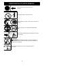
IDENTIFICATION OF SAFETY SYMBOLS
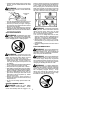
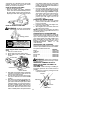
WARNING: This unit can be dangerous! Careless or improper
use can cause serious injury .
DANGER: Use only specified trimmer
head, spool, and 0.080 inch (2 mm) recommended
trimmer line. Never use blades, flailing devices,
wire, rope, string, etc. This attachment is designed
for line trimmer use only. Failure to follow these
instructions may result in serious injury.
Trimmer line can throw objects violently .
You can be blinded or injured. Always
wear hearing protection and safety
glasses marked Z87. Always wear head
protection, heavy, long pants, long
sleeves, boots and gloves.
Hazard zone for thrown objects.
S T rimmer line throws objects violently .
S You and others can be blinded/injured.
S Keep children, bystanders, and animals 50 feet
(15 meters) away.
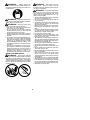
Secure hair above shoulder length. Do
not wear jewelry, loose clothing, or
clothing with loosely hanging straps,
ties, tassels, etc. They can be caught in
moving parts.
WARNING: Read the operator’s manual before use. Failure to
follow instructions could result in serious injury to the operator and/or
bystanders. Save operator’ s manual.

3
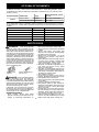
IDENTIFICATION OF SAFETY SYMBOLS
When servicing unit, use only identical replacement
parts.
Never allow children to operate this unit.
Store unit indoors in a high, dry place out of the reach of
children.
Always stop unit and disconnect spark plug before clean-
ing or servicing.
WARNING: Fire hazard. Never mix, pour, or store gasoline or
use the unit near a flame or sparks (including smoking, open flames, or
work that can cause sparks).
Use unleaded gasoline and two--stroke oil mixed at a ratio of
40:1 (2.5%).
Assist handle to be positioned only below
the arrow.

4
OPTIONAL ATT ACHMENTS
Cutting attachment / guard,
Powerhead model Attachments T ype part no.
Trimmer head TNG 7 537419214 / 530071824
Brushcutter attachment PPB4000C 952711828
Attachments Type Part no.
Edger attachment PPB1000E 952711825
Cultivator attachment PPB2000T 952711826
Blower attachment PPB3000B 952711827
Pruner attachment PPB5000P 952711906
Pruner attachment PPB5500P 952711671
These attachments used in combination with the specified powerhead have been evaluated
to applicable ISO-- and EN safety requirement standards by the Swedish Machinery Testing
Institute:
These attachments used in combination with the speci
f
ied powerhead ha
v
e been e
v
aluated
to ANSI B175.3--2003, “Grass Trimmers and Brushcutters -- Safety Requirements”. These
combinations have been evaluated by Underwriter’s Laboratories Inc. (UL) and are conse-
quently UL listed:
PPB330
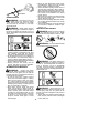
SAFETY RULES
WARNING: When using gardening
appliances, basic safety precautions must al-
ways be followed to reduce the risk of fire and
serious injury . Read and follow all instructions.
This power unit can be dangerous! Operator
is responsible for following instructions and
warnings on unit and in manual. Read entire
instruction manual before using unit! Be thor-
oughly familiar with the controls and the prop-
er use of the unit. Restrict the use of this unit
to persons who have read, understand, and
will follow the instructions and warnings on
the unit and in the manual. Never allow chil-
dren to operate this unit.
SAFETY INFORMATION
ON THE UNIT
INSTRUCTION
MANUAL
DANGER: Never use blades with line
trimmer attachment. Never use flailing de-
vices with any attachment. This unit (when
used with supplied line trimmer attachment) is
designed for line trimmer use only. Use of any
other accessories with line trimmer attach-
ment will increase the risk of injury.
If situations occur which are not covered in
this manual, use care and good judgment. If
you need assistance, contact your authorized
service dealer or call 1- 800-5 54-6723.
OPERATOR SAFETY
S Dress properly. Always wear safety
glasses or similar eye protection when op-
erating, or performing maintenance, on
your unit (safety glasses are available).
Eye protection should be marked Z87.
S Always wear face or dust mask if operation
is dusty .
S Always wear heavy, long pants, long
sleeves, boots, and gloves. Wearing safety
leg guards is recommended.
S Always wear foot protection. Do not go
barefoot or wear sandals. Stay clear of
spinning line.
S Secure hair above shoulder length. Secure
or remove loose clothing or clothing with
loosely hanging ties, straps, tassels, etc.
They can be caught in moving parts.
S Being fully covered also helps protect you
from debris and pieces of toxic plants
thrown by spinning line.
S Stay Alert. Do not operate this unit when you
are tired, ill, upset or under the influence of al-
cohol, drugs, or medication. Watch what you
are doing; use common sense.
S Wear hearing protection.
S Never start or run inside a closed room or
building. Breathing exhaust fumes can kill.
S Keep handles free of oil and fuel.
S Always keep engine on the right hand side
of your body.
S Hold the unit firmly with both hands.
S Keep trimmer head (or other optional at-
tachment) below waist level and away from
all parts of your body . Do not raise engine
above your waist.
S Keep all parts of your body away from muf-
fler and spinning line (or other optional at-
tachment). Keep engine below waist level.
A hot muf fler can cause serious burns.
S Keep firm footing and balance. Do not over-
reach or use from unstable surfaces such as
ladders, trees, steep slopes, rooftops, etc.

5
S Use only in daylight or good artificial light.
S Use only for jobs explained in this manual
(or manuals for optional attachments).
UNIT / MAINTENANCE SAFETY
S Disconnect the spark plug before perform-
ing maintenance except carburetor adjust-
ments.
S Look for and replace damaged or loose
parts before each use. Look for and repair
fuel leaks before use. Keep in good working
condition.
S Replace trimmer head parts that are
chipped, cracked, broken, or damaged in
any other way before using the unit.
S Maintain unit according to recommended pro-
cedures. Keep cutting line at proper length.
S Use only 0.080″ (2 mm) diameter Poulan
PRO brand line. Never use wire, rope,
string, etc.
S Install required shield properly before using
the unit. Use only specified trimmer head;
make sure it is properly installed and se-
curely fastened.
S Make sure unit is assembled correctly as
shown in this manual.
S Make carburetor adjustments with lower
end supported to prevent line from contact-
ing any object.
S Keep others away when making carburetor
adjustments.
S Use only recommended Po ulan PRO ac-
cessories and replacement parts.
S Have all maintenance and service not ex-
plained in this manual performed by an au-
thorized service dealer .
FUEL SAF ETY
S Mix and pour fuel outdoors.
S Keep away from sparks or flames.
S Use a container approved for fuel.
S Do not smoke or allow smoking near fuel or
the unit.
S Avoid spilling fuel or oil. Wipe up all fuel
spills.
S Move at least 10 feet (3 meters) away from
fueling site before starting engine.
S Stop engine and allow to cool before re-
moving fuel cap.
S Always store gasoline in a container ap-
proved for flammable liquids.
TRANSPORTING AND STORAGE
S Allow engine to cool before storing or trans-
porting in vehicle.
S Empty the fuel tank before storing or trans-
porting the unit. Use up fuel left in the carbu-
retor by starting the engine and letting it run
until it stops.
S Store unit and fuel in area where fuel vapors
cannot reach sparks or open flames from wa-
ter hea ters, electric motors or switches, fur-
naces, etc.
S Store unit so line limiter blade cannot acci-
dentally cause injury. The unit can be hung
by the shaft.
S Store unit out of reach of children.
WARNING: The engine exhaust
from this product contains chemicals known
to the State of California to cause cancer , birth
defects or other reproductive harm.
SAFETY NOTICE: Exposure to vibrations
through prolonged use of gasoline powered
hand tools could cause blood vessel or nerve
damage in the fingers, hands, and joints of
people prone to circulation disorders or abnor-
mal swellings. Prolonged use in cold weather
has been linked to blood vessel damage in
otherwise healthy people. If symptoms occur
such as numbness, pain, loss of strength,
change in skin color or texture, or loss of feeling
in the fingers, hands, or joints, discontinue the
use of this tool and seek medical attention. An
anti--vibration system does not guarantee the
avoidance of these problems. Users who oper-
ate power tools on a continual and regular basis
must monitor closely their physical condition
and the condition of this tool.
SPECIAL NOTICE: This unit is equipped
with a tempe rature lim iting muffle r and spark ar-
resting screen which meets the requirements of
California Codes 4442 and 4443. All U.S. forest
land and the states of California, Idaho, Maine,
Minnesota, New Jersey, Oregon, and W ashing-
ton require by law that many internal combus-
tion engines be equipped with a spark arresting
screen. If you operate in a locale where such
regulations exist, you are legally responsible for
maintaining the operating condition of these
parts. Failure to do so is a violation of the law .
For normal homeowner use, the muffler and
spark arresting screen will not require any ser-
vice. After 50 hours of use, we recommend that
your muf fler be serviced or replaced by an au-
thorized service dealer.
LINE TRIMMER SAFETY
WARNING: Inspect the area to be
trimmed before each use. Remove objects
(rocks, broken glass, nails, wire, etc.) which
can be thrown by or become entangled in line.
Hard objects can damage the trimmer head
and be thrown causing serious injury.
S Keep others including children , anim als, by-
standers, and helpers at least 50 feet (15 me-
ters) away. Bystanders should be encour-
aged to wear safety glasses. Stop engine
immediately if you are approached.
S Use only for trimming, scalping, mowing and
sweeping. Do not use for edging, pruning or
hedge trimming.
S Cut from your right to your left. Cutting on
left side of the shield will throw debris away
from the operator.
ADDITIONAL SAFETY RULES
FOR OPT IONAL ATTACHMENT S
WARNING: For each optional at-
tachment used, read entire instruction manu-
al before use and follow all warnings and in-
structions in manual and on attachment.
WARNING: Ensure handlebar is
installed when using brushcutter attachment.
Attach handlebar above arrow on safety label
on the upper shaft (engine end of unit). If your
brushcutter attachment does not include a han-
dlebar , a handlebar accessory kit (#530071451)
is available from your authorized service dealer .

6
Handlebar
EDGER SAFET Y
WARNING: Inspect the area to be
edged before each use. Remove objects
(rocks, broken glass, nails, wire, etc.) which
can be thrown by the blade or can wrap
around the shaft.
WARNING: Blade rotates momen-
tarily after the trigger is released or engine is
turned of f. The blade can seriously cut you or
others. Allow blade to stop before removing it
from the cut.
S Throw away blades that are bent, warped,
cracked, broken or damaged in any other
way. Replace parts that are cracked,
chipped, or damaged before using the unit.
S Do not attempt to remove cut material nor
hold material to be cut when the engine is
running or when cutting blade is moving.
S Always keep the wheel and depth adjusting
skid in contact with the ground.
S Always push the unit slowly over the
ground. Stay alert for uneven sidewalks,
holes in the terrain, large roots, etc.
BLOWER/VACUUM SAFETY
WARNING: Inspect area before
starting unit. Remove all debris and hard ob-
jects such as rocks, glass, wire, etc. that can
ricochet, be thrown, or otherwise cause injury
or damage during operation.
S Do not set unit on any surface except a
clean, hard area while engine is running.
Debris such as gravel, sand, dust, grass,
etc., could be picked up by the air intake
and thrown out through discharge opening,
damaging unit, property, or causing serious
injury to bystanders or operator.
S Never place objects inside the blower
tubes, vacuum tubes or blower outlet. Al-
ways direct the blowing debris away from
people, animals, glass, and solid objects
such as trees, automobiles, walls, etc. The
forceof aircan causerocks, dirt, or sticks to
be thrown or to ricochet which can hurt
people or animals, break glass, or cause
other damage.
S Never run unit without the proper equip-
ment attached. When using your unit as a
blower, always install blower tubes.
S Check air intake opening, blower tubes or
vacuum tubes frequently, always with en-
gine stopped and spark plug disconnected.
Keep vents and discharge tubes free of de-
bris which can accumulate and restrict
proper air flow.
S Never place any object in air intake opening
as this could restrict proper air flow and
cause damage to the unit.
S Never use for spreading chemicals, fertiliz-
ers, or other substances which may contain
toxic materials.
S To avoid spreading fire, do not use near leaf
or brush fires, fireplaces, barbecue pits,
ashtrays, etc.
BRUSHCUTTER SAFETY
DANGER: Blade can thrust violently
away from material it does not cut. Blade
thrust can cause amputation of arms or legs.
WARNING: Do not use trimmer head
as a fastening device for the blade.
WARNING: The blade continues to
spin after the trigger is released or engine is
turned off. The coasting blade can throw ob-
jects or seriously cut you if accidentally
touched. Stop the blade by contacting the
right hand side of the coasting blade with ma-
terial already cut.
WARNING: Inspect the area to be
cut before each use. Remove objects (rocks,
broken glass, nails, wire, etc.) which can be
thrown or become entangled in the blade or
trimmer line.
S Throw away and replace blades that are
bent, warped, cracked, broken or damaged
in any other way.

7
S Install required shield properly before using
the unit. Use the metal shield for all metal
blade use.
WARNING: Only use brushcutter at-
tachments that provide a metal shield with
proboscis nose.
Proboscis
nose
S Use only specified blade and make sure it is
properly installed and securely fastened.
S Cut from your left to your right. Cutting on
the right side of the shield will throw debris
away from the operator.
S Always use the handlebar and a properly
adjusted shoulder strap with blade (see AS-
SEMBLY instructions in brushcutter attach-
ment instruction manual).
CULTIVATOR SAFETY
WARNING: Rotating tines can cause
serious injury. Keep away from rotating tines.
Stop the engine and disconnect the spark plug
before unclogging tines or making repairs.
WARNING: Inspect the area to be
cultivated before starting the unit. Remove all
debris and hard and sharp objects such as
rocks, vines, branches, rope, string, etc.
S Avoid heavy contact with solid objects that
might stop the tines. If heavy contact oc-
curs, stop the engine and inspect the unit
for damage.
S Never operate the cultivator without the tine
cover in place and properly secured.
S Keep the tines and guard clear of debris.
S After striking a foreig n object, stop the engine,
disconnect the spark plug and inspect the cul-
tivator for damage. Repair before restarting.
S Disconnect attachment from the drive en-
gine before cleaning the tines with a hose
and water to remove any build--up. Oil the
tines to prevent rust.
S Always wear gloves when servicing or
cleaning the tines. The tines become very
sharp from use.
S Do not run unit at high speed unless culti-
vating.
HEDGE TRIMMER SAFET Y
DANGER: RISK OF CUT; KEEP
HANDS AWAY FROM BLADE -- Blade
moves momentarily after the trigger is re-
leased or engine is turned off. Do not attempt
to clear away cut material when the blade is in
motion. Make sure the engine is turned off,
the spark plug wire is disconnected, and the
blade has stopped moving before removing
jammed material from the cutting blade. Do
not grab or hold the unit by the cutting blade.
WARNING: Inspect the area before
starting the unit. Remove all debris and hard
objects such as rocks, glass, wire, etc. that
can ricochet, be thrown, or otherwise cause
injury or damage during operation.
S Do not use a cutting blade that is bent,
warped, cracked, broken or damaged in any
other way. Have worn or damaged parts re-
placed by your authorized service dealer.
S Always keep unit in front of your body .
Keep all parts of your body away from the
cutting blade.
S Keep the cutting blade and air vents clear of
debris.
POLE PRUNER SAFETY
WARNING: The reciprocating blade/
rotating chain can cause severe injury. In-
spect the unit before use. Do not operate unit
with a bent, cracked or d ull blade or dull chain.
Keep away from the blade/chain.
WARNING: The reciprocating blade/
rotating chain is sharp. Do not touch. To pre-
vent serious injury , always stop engine and
ensure blade/chain has stopped moving, dis-
connect spark plug, and wear gloves when
changing or handling the blade or chain.
WARNING: A coasting blade/rotat-
ing chain can cause injury while it continues to
move after the engine is stopped. Maintain
proper control of the unit until the blade/chain
has completely stopped moving. Keep
hands, face and feet at a distance from all
moving parts. Do not attempt to touch or stop
the blade or chain when it is moving.

8
WARNING: Falling objects can
cause severe head injury. Wear head protec-
tion when operating this unit with a pole prun-
er attachment.
WARNING: To prevent serious inju-
ry, do not use more than one boom extension
with a pole pruner attachment.
WARNING: Keep the pruner away
from power lines or electrical wires.
S Only use for pruning limbs or branches up
to 6 inches (15 cm) in diameter.
S Do not operate the unit faster than the
speed needed to prune. Do not run the unit
at high speed when not pruning.
S Always stop the unit when work is delayed
or when walking from one cutting location to
another.
S If you strike or become entangled with a for-
eign object, stop the engine immediately
and check for damage. Have any damage
repaired by an authorized service dealer
before attempting further operations. Dis-
card blades that are bent, warped, cracked
or broken.
S Stop the unit immediately if you feel exces-
sive vibration. Vibration is a sign of trouble.
Inspect thoroughly for loose nuts, bolts or
damage before continuing. Contact an au-
thorized service dealer for repair or re-
placement of affected parts as necessary.
SNOW THROWER SAFETY
WARNING: Keep hands and feet
away from the rotor when starting or running
the engine. Never attempt to clear the rotor
with the engine/motor running. Stop engine
and disconnect spark plug before unclogging
snow or debris from discharge chute or when
adjusting vanes.
WARNING: Never lean over dis-
charge chute. Rocks or debris could be
thrown into the eyes and face and cause seri-
ous injury or blindness.
WARNING: Inspect the area where
the unit is to be used. Remove objects that
could be thrown or damage the unit. Some
objects may be hidden by fallen snow -- be
alert for the possibility.
S Direct material discharge away from glass
enclosures, automobiles, etc.
S Do not run engine at high speed while not
removing snow .
S Be attentive when using the snowthrower,
and stay alert for holes in the terrain and
other hidden hazards.
S Make sure the rotor will spin freely before
attaching the snowthrower to the power-
head.
S If the rotor will not rotate freely due to frozen
ice, thaw the unit before thoroughly before
attempting to operate under power .
S Keep the rotor clear of debris.
S Do not throw snow near other people. The
snow thrower could propel small objects at
high speed causing injury.
S After striking a foreign object, stop the en-
gine, disconnect spark plug and inspect the
snowthrower for damage and repair if nec-
essary before restarting unit.
S Never operate the snowthrower near glass
enclosures, automobiles and trucks.
S Never attempt to use the snowthrower on a
roof.
S Never operate the snowthrower near win-
dow wells, dropoffs, etc.
S Never discharge snow onto public roads or
near moving traffic.
S Clear snow from slopes by going up and
down; never across. Use caution when
changing directions. Never clear snow from
steep slopes.
S Let snowthrower run for a few minutes after
clearing snow so moving parts do not freeze.
S Look behind and use care when backing
up. Exercise caution to avoid slipping or fal-
ling, especially when operating in reverse.
S Know how to stop quickly.

9
ASSEMBLY
WARNING: If received assembled,
repeat all steps to ensure your unit is properly
assembled and all fasteners are secure.
Examine parts for damage. Do not use dam-
aged parts.
NOTE: If you need assistance or find parts
missing or damaged, call 1-800-554-6723.
It is normal for the fuel filter to rattle in the
empty fuel tank.
Finding fuel or oil residue on muffler is normal
due to carburetor adjustments and testing
done by the manufacturer.
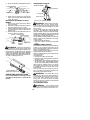
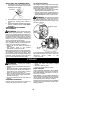
INSTALLING TRIMMER ATTACH-
MENT
CAUTION:
When installing trimmer attach-
ment, place the unit on a flat surface for stabil-
ity.
1. Loosen the coupler by turning the knob
counterclockwise.
Shipping
protector
Coupler
Knob
LOOSEN
TIGHTEN
2. Remove shipping protector from coupler.
3. Remove the shaft cap from the trimmer
attachment (if present).
4. Position locking/release button of attach-
ment into guide recess of coupler.
5. Push the attachment into the coupler until
the locking/release button snaps into the
primary hole.
6. Before using the unit, tighten the knob se-
curely by turning clockwise.
Coupler
Primary Hole
Upper
Shaft
Locking/
Release
Button
Attachment
Guide Recess
WARNING: Make sure the locking/
release button is locked in the primary hole
and the knob is securely tightened before op-
erating the unit. All atta c hments a re de s igned
to be used in the primary hole unless otherwise
stated in the applicable attachment instruction
manual. Using the wrong hole could lead to seri-
ous injury or damage to the unit.
Locking/Release
Button in Primary Hole
For assembly of optional attachments (see
list on page 11), refer to the ASSEMBLY sec-
tion of the applicable attachment instruction
manual.
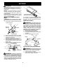
ATTACHING SHIELD
WARNING: The shield must be prop-
erly installed. The shield provides partial protec-
tion from the risk of thrown objects to the opera-
tor and others and is equipped with a line limiter
blade which cuts excess line to the proper
length. The line limiter blade (on underside of
shield) is sharp and can cut you. For proper
orientatio n of shield, see KNOW YOUR TRIM-
MER illustration in OPERATION section.
1. Remove wing nut from shield.
2. Insert bracket into slot as shown.
3. Pivot shield until bolt passes through hole
in bracket.
4. Securely tighten wing nut onto bolt.
Slot
Shield
Wing
nut
Bracket
Line limiter blade
ADJUSTING THE ASSIST HANDLE
WARNING: When adjusting the assist
handle, be sure it remains above the safety label
and below the mark or arrow on the shaft.
1. Loo sen wing nut on handle.
2. Rotate the handle on the shaft to an up-
right position; retighten wing nut.

10
OPERATION
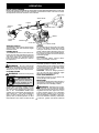
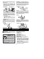
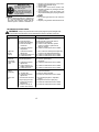
KNOW YOUR TRIMMER
READ THIS INSTRUCTION MANUAL AND SAFETY RULES BEFORE OPERA TING YOUR UNIT.
Compare the illustrations with your unit to familiarize yourself with the location of the various controls
and adjustments. Save this manual for future reference.
Line limiter
blade
Assist handle
Starter handle
Choke lever
Shield
Trimmer
head
Shaft
Muffler
ON/STOP switch
Coupler
Throttle trigger
Spark plug
Primer bulb
ON/STOP SWITCH
The ON/STOP switch is used to stop engine. To
stop the engine, push and release the engine
ON/STOP swit ch.
PRIMER BULB
The PRIMER BULB removes air from the car-
buretor and fuel lines and fills them with fuel.
This allows you to start the engine with fewer
pulls on the starter rope. Activate the primer
bulb by pressing it and allowing it to return to
its original form.
CHOKE
The CHOKE helps to supply fuel to the engine
toaidincoldstarting.Activatethechokeby
moving the choke lever to the FULL CHOKE
position. After the engine attempts to start, move
the choke lever to the HALF CHOKE position.
Once engine has started, move the choke lever
to the RUN position.
COUPLER
The COUPLER enables optional attach-
ments to be installed on the unit.
BEFORE STARTING EN GINE
WARNING: Be sure to read the fuel
information in the safety rules before you begin.
If you do not understand the safety rules, do not
attempt to fuel your unit. Call 1-800-554-6723.
FUELING ENGINE
WARNING: Remove fuel cap slowly
when refueling.
HELPFUL TIP
To obtain the correct oil mix
ratio, pour 3.2 ounces of
2-- cycle synthetic oil into
one gallon of fresh gas.
This engine is certified to operate on unleaded
gasoline. Before operation, gasoline must be
mixed with a good quality synthetic 2-cycle
air-cooled engine oil designed to be mixed at a
ratio of 40:1. Poulan/WEED EA TER brand
synthetic oil is recommended. Mix gasoline and
oil at a ratio of 40:1. A 40:1 ratio is obtained by
mixin g 3.2 fluid o unces (95 ml) of o il wit h 1
gallon (4 liters) of unleaded gasoline. DO NOT
USE automotive oil or marine oil. These oils will
cause engine damage. When mixing fuel, follow
instructions printed on container . Once oil is
added to gasoline, shake container momentarily
to assure that the fuel is thoroughly mixed.
Always read and follow the safety rules relating
to fuel before fueling your unit.
CAUTION: Never use straight gasoline in
your unit. This will cause permanent engine
damage and void the limited warranty.
FUEL REQUIREMENTS
This engine requires the use of minimum 87
octane [R+M]/2 clean gasoline.
IMPORTAN T
Use of alcohol blended fuels (called gasohol or
using ethanol or methanol) can cause major en-
gine performance and durability problems.
WARNING: Alternative fuels (not gas-
oline) such as E--15 (15% alcohol), E--20 (20%
alcohol), E--85 (85% alcohol) are NOT classified
as gasoline and are NOT approved for use in
2--stroke gasoline engines. Use of alternative
fuels will cause problems such as: improper
clutch engagements, overheating, vapor lock,
power loss, lubrication deficiency, deterioration
of fuel lines, gaskets and internal carburetor

11
components, etc. Alternative fuels cause high
moisture absorption into the fuel/oil mixture
leading to oil and fuel separation.
HOW TO STOP YOUR UNIT
S Release the throttle trigger.
S Push and release the engine ON/STOP
swit ch. T h e swit ch wi l l aut o mat i ca l l y ret u rn to
the ON position. W ait 5 seconds before at-
tempting to restart unit to allow switch to reset.
ON/STOP switch
HOW TO START YOUR UNIT
WARNING: Avoid any contact with the
muffler . A hot muffler can cause serious burns.
Starting position
HELPFUL TIP
If your engine still does not
start after following these
instructions, please call
1--800--554--6723.
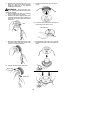
STARTING A COLD ENGINE (or a
warm engine after running out of
fuel)
1. Set unit on a flat surface.
2. Slowly press the primer bulb 6 times.
3. Move choke lever to the FULL CHOKE
position.
Choke lever
Starter handle
Primer bulb
Muffler
4. Pull starter rope handle sharply until engine
sounds as if it is trying to start, but do not
pull rope more than 6 times.
5. As soon as engine sounds as if it is trying to
start, move choke lever to HALF CHOKE
position.
6. Pull starter rope sharply until engine runs,
but no more than 6 pulls.
NOTE: If the en-
gine doesn’t start after 6 pulls (at the HALF
CHOKE position), move the choke lever to
the FULL CHOKE position and press the
primer bulb 6 times. Pull the starter rope 2
more times. Move the choke lever to the
HALF CHOKE position and pull the starter
rope until the engine runs, but no more than
6 pulls. If the engine still doesn’t start, it is
probably flooded. Proceed to ST ARTING A
FL OODE D ENGINE .
7. Once the engine starts, allow it to run 10
seconds. Squeeze throttle trigger and allow
the unit to run for 30 more seconds at RUN.
Release throttle trigger.
NOTE: If engine
dies with the choke lever in the RUN posi-
tion, move the choke lever to FULL
CHOKE then back to HALF CHOKE and
pull the rope until engine runs, but no
more than 6 pulls.
STARTING A WARM ENGINE
1. M ove choke lever to the FULL CHOKE
position, then to the HALF CHOKE posi-
tion to set fast idle.
2. Pull starter rope sharply until engine runs,
but no more than 6 pulls.
3. Allow engine to run 15 seconds, then move
the choke lever to RUN.
NOTE: If engine has not started, pull starter
rope 5 more pulls. If engine still does not run, it
is probably flooded.
STARTING A FLOODED ENGINE
Flooded engines can be started by placing the
choke lever in the RUN position; then, pull the
rope to clear the engine of excess fuel. This
could require pulling the starter handle many
times depending on how badly the unit is
flooded. If the unit still doesn’t start, refer to
TROUBLESHOOTING T ABLE or call
1-800-554-6723.
OPERATING THE COUPLER
This model is equipped with a coupler which
enables optional attachments to be installed.
The optional attachments are:
MODEL:
Edger PPB1000E......................
Cultivator PPB2000T...................
Blower PPB3000B.....................
Brushcutter PPB4000C.................
Pruner PPB5000P.....................
Pruner PPB5500P.....................
WARNING: Always stop unit and dis-
connect spark plug before removing or instal-
ling attachments.
REMOVING TRIMMER ATTACH -
MENT (OR OTHER OPTIONAL AT -
TACHMENTS)
CAUTION:
When removing or installing at-
tachments, place the unit on a flat surface for
stability .
1. Loo sen the coupler by turning the knob
counterclockwise.
Attachment
Coupler
Knob
LOOSEN
TIGHTEN

12
2. Press and hold the locking/release button.
Locking/Release
Button
Coupler
Upper Shaft
Attachment
3. While securely holding the engine and
upper shaft, pull the attachment straight
out of the coupler .
INSTALLING OPTIONAL ATTACH -
MENTS
1. Remove the shaft cap from the attach-
ment (if present).
2. Position locking/release button of attach-
ment into guide recess of coupler.
3. Push the attachment into the coupler until
the locking/release button snaps into the
primary hole.
4. Before using the unit, tighten the knob se-
curely by turning clockwise.
Coupler
Primary Hole
Upper
Shaft
Locking/
Release
Button
Attachment
Guide Recess
WARNING: Make sure the locking/
release button is locked in the primary hole
and the knob is securely tightened before op-
erating the unit. All atta c hments a re de s igned
to be used in the primary hole unless otherwise
stated in the applicable attachment instruction
manual. Using the wrong hole could lead to seri-
ous injury or damage to the unit.
Locking/Release
Button in Primary Hole
OPERATING INSTRUCTIONS
It is recommended that the engine not be
operated for longer than 1 minute at full
throttle.
OPERATING POSITION
Eye protection
Long pants
Heavy shoes
ALWAYS WEAR:
Cut from your right to your left.
WARNING: Always wear eye protec-
tion. Never lean over the trimmer head.
Rocks or debris can ricochet or be thrown into
eyes and face and cause blindness or other
serious injury.
Do not run the engine at a higher speed than
necessary. The cutting line will cut efficiently
when the engine is run at less than full throttle.
At lower speeds, there is less engine noise and
vibration. The cutting line will last longer and will
be less likely to “weld” onto the spool.
Always release the throttle trigger and allow the
engine to return to idle speed when not cutting.
To stop engine:
S Release the throttle trigger.
S Push and release the engine ON/STOP
switch.
TRIMMER LINE ADVANCE
The trimmer line will advance approximately 2
inches (5 cm) each time the bottom of the
trimmer head is tapped on the ground with the
engine running at full throttle.
The most efficient line length is the maximum
length allowed by the line limiter.
Always keep the shield in place when the tool
is being operated.
To advance line:
S Operate the engine at full throttle.
S Hold the trimmer head parallel to and above
the grassy area.
S Tap the bottom of the trimmer head lightly on
the ground one time. Approximately 2 inches
(5 cm) of line will be advanced with each tap.
Always tap the trimmer head on a grassy
area. Tapping on surfaces such as concrete
or asphalt can cause excessive wear to the
trimmer head.
If the line is worn down to 2 inches (5 cm) or
less, more than one tap will be required to ob-
tain the most efficient line length.
WARNING: Use only 0.080″ (2 mm)
diameter line. Other sizes of line will not ad-
vance properly and can cause serious injury.
Do not use other materials such as wire,
string, rope, etc. Wire can break off during
cutting and become a dangerous missile that
can cause serious injury.
CUTTING METHODS
WARNING: Use minimum speed
and do not crowd the line when cutting around
hard objects (rock, gravel, fence posts, etc.),

13
which can damage the trimmer head, become
entangled in the line, or be thrown causing a
serious hazard.
S The tip of the line does the cutting. You will
achieve the best performance and
minimum line wear by not crowding the line
into the cutting area. The right and wrong
ways are shown below.
Tip of the line
does the cutting
Right
Line crowded Into
work area
Wrong
S The line will easily remove grass and
weeds from around walls, fences, trees and
flower beds, but it also can cut the tender
bark of trees or shrubs and scar fences.
S For trimming or scalping, use less than full
throttle to increase line life and decrease head
wear, especially:
S During light duty cutting.
S Near objects around which the line can
wrap such as small posts, trees or fence
wire .
S F or mowi ng or sweeping, use full throttle for
a good clean job.
TRIMMING -- Hold the bottom of the trimmer
head about 3 inches (8 cm) above the ground
and at an angle. Allow only the tip of the line to
make contact. Do not force trimmer line into
work area.
Trimming
3 inches (8 cm)
above ground
SCALPING -- The scalping technique re-
moves unwanted vegetation down to the
ground. Hold the bottom of the trimmer head
about 3 inches (8 cm) above the ground and
at an angle. Allow the tip of the line to strike the
ground around trees, posts, monuments, etc.
This technique increases line wear.
Scalping
MOWING -- Your trimmer is ideal for mowing
in places conventional lawn mowers cannot
reach. In the mowing position, keep the line
parallel to the ground. Avoid pressing the
head into the ground as this can scalp the
ground and damage the tool.
Mowing
SWEEPING -- The fanning action of the rotat-
ing line can be used for a quick and easy
clean up. Keep the line parallel to and above
the surfaces being swept and move the tool
from side to side.
Sweeping
MAINTENANCE
WARNING: Disconnect the spark
plug before performing maintenance except
for carburetor adjustments.
HELPFUL TIP
IMPORT ANT: Have all
repairs other than the rec-
ommended maintenance
described in the instruction
manual performed by an
authorized service dealer.
If any dealer other than an authorized
service dealer performs work on the
product, Poulan PRO may not pay for
repairs under warranty. It is your re-
sponsibility to maintain and perform
general maintenance.
CHECK FOR LOOSE
FASTENERS AND PARTS
S Spark Plug Boot
S Air Filter
S Housing Screws
S Assist Handle Screw
S Debris Shield
CHECK FOR DAMAGED OR
WORN PARTS
Contact an authorized service dealer for re-
placement of damaged or worn parts.
S ON/STOP Switch -- Ensure ON/STOP
switch functions properly by pushing and
releasing the switch. Make sure engine
stops. W ait 5 seconds before attempting to
restart unit to allow switch to reset. Restart
engine and continue.
S Fuel Tank -- Discontinue use of unit if fuel
tank shows signs of damage or leaks.
S Debris Shield -- Discontinue use of unit if
debris shield is damaged.

14
INSPECT AND CLEAN UNIT AND
LABELS
S After each use, inspect complete unit for
loose or damaged parts. Clean the unit and
labels using a damp cloth with a mild deter-
gent.
S Wipe off unit with a clean dry cloth.
CLEAN A IR F ILTER
A dirty air filter decreases engine perform-
ance and increases fuel consumption and
harmful emissions. Always clean after every
5 hours of operation.
1. Clean the cover and the area around it to
keep dirt from falling into the carburetor
chamber when the cover is removed.
2. Loosen bolt with a 5/16 inch (8 mm) socket
wrench. Remove air filter cover and air filter .
NOTE: To avoid creating a fire hazard or
producing harmful evaporative emissions, do
not clean filter in gasoline or other flammable
solvent.
3. Wash the filter in soap and water.
4. Allow filter to dry.
5. Replace parts.
Bolt
Air filter cover
Air filter
MUFFLER AND SPARK ARREST-
ING SCREEN
WARNING: The muffler on this prod-
uct contains chemicals known to the State of
California to cause cancer.
As your unit is used, carbon deposits build up
on the muffler and spark arresting screen.
For normal homeowner use, however, the
muffler and spark arresting screen will not re-
quire any service. After 50 hours of use, we
recommend that your muffler be serviced or
replaced by your authorized service dealer.
REPLACE SPARK PLUG
Replace the s park plug each y ear to ensur e
the engine starts easier and runs better.
Inspec t s park plug every 25 hours of usage.
Clean and/or replace as necessary. Set spark
plug gap at 0.025 inch (0.6 mm). Ignition tim-
ing is fixed and nonadjustable.
NOTE: This spark ignition system complies
with the Canadian standard ICES--002.
1. Twist, then pull off spark plug boot.
2. Remove spark plug from cylinder and
discard.
3. Replace with Champion RCJ-6Y spark
plug and tighten securely with a 3/4 inch
(19 mm) socket wrench.
4. Reinstall the spark plug boot.
SERVICE AND ADJUSTMENTS
REPLACING THE LINE
1. Press the tabs on the side of the trimmer
head and remove cover and spool.
Tab
Tab
Cover
Spool
2. Remove any remaining line.
3. Clean dirt and debris from all parts. Re-
place spool if it is worn or damaged.

15
4. Replace with a pre-wound spool, or re-
place line using a 25 feet (8 meters)
length of 0.080 inch (2 mm) diameter
Poulan PRO brand line.
WARNING: Never use wire, rope,
string, etc., which can break off and become a
dangerous missile.
5. When installing new line on an existing
spool, hold the spool as shown.
6. Bend the line at the midpoint and insert
the bend into the slot in the center rim of
the spool. Ensure line snaps into position
in the slot.
Slot
7. With your finger between the lines, wrap
the lines evenly and firmly around the
spool in a clockwise direction.
8. Position the lines in the guide slots.
Guide slot
Guide slot
9. Place the spool in the cover as shown
below.
10. Insert the ends of the lines through exit
holes in the sides of the cover.
Line exit hole
Cover
11. Reinstall the spool and cover onto the
trimmer head. Push until cover snaps into
place.

16
REPLACING THE TRIMMER HEAD
1. Hold the dust cup with a wrench to keep
the shaft from turning while removing and
installing trimmer head.
Dust Cup
2. Remove trimmer head by turning coun-
terclockwise (looking from bottom of
unit).
3. Thread replacement trimmer head onto the
shaft by turning clockwise. Only tighten
hand tight!
CARBURETOR IDLE SPEED
ADJUSTMENT
WARNING: Keep others away when
making idle speed adjustments. The trimmer
head or any optional attachment will be spin-
ning during most of this procedure. Wear your
protective equipment and observe all safety
precautions. After making adjustments, the
trimmer head or any optional attachment
must not move/spin at idle speed.
The carburetor has been carefully set at the
factory. Adjustments may be necessary if you
notice any of the following conditions:
S Engine will not idle when the throttle is
released.
S The trimmer head or any optional
attachment moves/spins at idle.
Make adjustments with the unit supported so
the cutting attachment is off the ground and
will not make contact with any object. Hold
the unit by hand while running and making ad-
justments. Keep all parts of your body away
from the cutting attachment and muffler .
To adjust idle speed:
Allow engine to idle. Adjust speed until engine
runs without trimmer head or any optional at-
tachment moving or spinning (idle too fast) or
engine stalling (idle speed too slow).
S Turn idle speed screw clockwise to increase
engine speed if engine stalls or dies.
S Turn idle speed screw counterclockwise to
decrease engine speed if trimmer head or any
optional attachment moves or spins at idle.
WARNING: Recheck the idle speed
after each adjustment. The trimmer head or
any optional attachment must not move or
spin at idle speed to avoid serious injury to the
operator or others.
Air filter
cover
Id l e speed screw
If you require further assistance or are unsure
about performing this procedure, contact an
authorized service dealer or call
1--800--554--6723.
STORAGE
WARNING: Perform the following
steps after each use:
S Allow engine to cool before storing or trans-
porting.
S Store unit and fuel in a well ventilated area
where fuel vapors cannot reach sparks or
open flames from water heaters, electric
motors or switches, furnaces, etc.
S Store unit with all guards in place. Position
unit so that any sharp object cannot acci-
dentally cause injury.
S Store unit and fuel well out of the reach of
children.
SEASONAL STORAGE
Prepare unit for storage at end of season or if
it will not be used for 30 days or more.
If your unit is to be stored for a period of time:
S Clean the entire unit before lengthy
storage.
S Store in a clean dry area.
S Lightly oil external metal surfaces.
FUEL SYSTEM
Under FUELING ENGINE in the OPERA-
TION section of this manual, see message la-
beled IMPORTANT regarding the use of ga-
sohol in your engine.
Fuel stabilizer is an acceptable alternative in
minimizing the formation of fuel gum deposits
during storage. Add stabilizer to the gasoline
in the fuel tank or fuel storage container .
Follow the mix instructions found on stabilizer
container. Run engine at least 5 minutes after
adding stabilizer.

17
HELPFUL TIP
During storage of your gas/
oil mixture, the oil will sepa-
rate from the gas.
We recommend that you
shake the gas can weekly
to insure proper blending of
the gas and oil.
ENGINE
S Remove spark plug and pour 1 teaspoon of
40:1, 2-cycle engine oil (air cooled) through
the spark plug opening. Slowly pull the
starter rope 8 to 10 times to distribute oil.
S Replace spark plug with new one of recom-
mended type and heat range.
S Clean air filter .
S Check entire unit for loose screws, nuts,
and bolts. Replace any damaged, broken,
or worn parts.
S At the beginning of the next season, use
only fresh fuel having the proper gasoline to
oil ratio.
OTHER
S Do not store gasoline from one season to
another.
S Replace your gasoline can if it starts to rust.
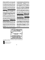
TROUBLE CAUSE REMEDY
Engine will not
start.
1. Engine flooded.
2. Fuel tank empty.
3. Spark plug not firing.
4. Fuel not reaching
carburetor.
5. Carburetor requires
adjustment.
1. See “Starting a Flooded Engine” in
Operation Section.
2. Fill tank with correct fuel mixture.
3. Install new spark plug.
4. Check for dirty fuel filter; replace.
Check for kinked or split fuel line;
repair or replace.
5. Contact an authorized service dealer .
Engine will
not idle
properly.
1. Carburetor requires
adjustment.
2. Crankshaft seals worn.
3. Compression low.
1. See “Carburetor Idle Speed Adjustment”
in Service and Adjustments Section.
2. Contact an authorized service dealer .
3. Contact an authorized service dealer .
1. Air filter dirty .
2. Spark plug fouled.
3. Carburetor requires
adjustment.
4. Carbon build-up on
muffler outlet screen.
5. Compression low.
Engine will not
accelerate,
lacks power,
or dies under
a load.
1. Clean or replace air filter.
2. Clean or replace plug
and regap.
3. Contact an authorized service dealer .
4. Contact an authorized service dealer .
5. Contact an authorized service dealer .
Engine
smokes
excessively .
1. Fuel mixture incorrect.
2. Air filter dirty .
3. Carburetor requires
adjustment.
1. Empty fuel tank and refill with
correct fuel mixture.
2. Clean or replace air filter.
3. Contact an authorized service dealer .
Engine runs
hot.
1. Fuel mixture incorrect.
2. Spark plug incorrect.
3. Carburetor requires
adjustment.
4. Carbon build-up on
muffler outlet screen.
1. See “Fueling Engine” in Operation
section.
2. Replace with correct spark plug.
3. Contact an authorized service dealer .
4. Contact an authorized service dealer .
WARNING: Always stop unit and disconnect spark plug before performing all of the
recommended remedies below except remedies that require operation of the unit.
TROUBLESHOOTING TAB LE

18
LIMITED WARRANTY
Poulan PRO, a division of Husqvarna
Consumer Outdoor Products N.A., Inc., war-
rants to the original consumer purchaser that
each new Poulan PRO brand gasoline tool or
attachment is free from defects in material and
workmanship and agrees to repair or replace
under this warranty any defective gasoline prod-
uct or attachment as follows from the original
date of purchase.
2YEARS--Parts and Labor , when used for
household purposes.
90 DA YS -- Parts and Labor, when used for
commercial, professional, or income producing
purposes.
30 DAYS -- Parts and Labor , if used for rental
purposes.
This warranty is not transferable and does not
cover damage or liability caused by improper
handling, improper maintenance or alteration, or
the use of accessories and/or attachments not
specifically recommended by Poulan PRO for
this tool. This warranty does not cover tune--up,
spark plugs, filters, starter ropes, cutting line, or
rotating head parts that will wear and require re-
placement with reasonable use during the war-
ranty period. This warranty does not cover pre--
delivery setup or normal adjustments explained
in the instruction manual. This warranty does
not cover transportation costs.
In the event you have a claim under this warran-
ty, you must return the product to an authorized
service dealer .
Should you have any unanswered questions
concerning this warranty, please contact:
Poulan PRO, a division of Husqvarna
Consumer Outdoor Products N.A., Inc.
7349 Statesville Road
Charlotte, NC 28269
1--800--554--6723
In Canada, contact:
Poul an PRO
850 Matheson Blvd. West
Mississauga, Ontario L5V 0B4
Giving the model number , serial number and
date of purchase of your product and the name
and address of the authorized dealer from
whom it was purchased.
THIS WARRANTY GIVES YOU SPECIFIC
LEGAL RIGHTS, A ND YOU MAY HA V E OTH-
ER RIGHTS WHICH V AR Y FROM STATE T O
STATE.
NO CLAIMS FOR CONSEQUENTIAL OR
OTHER DAMAGES WILL BE ALL OWE D,
AND THERE ARE NO OTHER EXPRESS
WARRANTIES EXCEPT THOSE EX-
PRESSL Y STIPULATED HEREIN.
SOME ST ATES DO NOT ALLOW LIMITA-
TIONS ON HOW LONG AN IMP L IE D WAR-
RANTY LAST S OR THE EXCLUS ION OR
LIMITATIONS OF INCIDENTAL OR CONSE-
QUENTIAL DAMAGES, SO THE ABOVE LIM-
ITATIONS OR EXCLUSION MAY NOT APPL Y
TO YOU.
This is a limited warranty within the meaning of
that term as defined in the Magnuson--Moss Act
of 1975.
The policy of Poulan PRO is to continuously
improve its products. Therefore, Poulan PRO
reserves the right to change, modify, or dis-
continue models, designs, specifications,
and accessories of all products at any time
without notice or obligation to any purchaser.
U.S. EPA/CALIFORNIA/ENVIRONMENT CANADA
EMISSION CONTROL WARRANTY STATE MENT
YOUR WARRANTY RIGHTS AND OB-
LIGATIONS: The U.S. Environmental
Protection Agency, California Air Resources
Board, Environment Canada and Poulan
PRO are pleased to explain the emissions
control system warranty on your year 2010
and later small off--road engine. In California,
all small off--road engines must be designed,
built, and equipped to meet the State’s strin-
gent anti--smog standards. Poulan PRO must
warrant the emission control system on your
small off--road engine for the periods of time
listed below provided there has been no
abuse, neglect, or improper maintenance of
your small off--road engine. Your emission
control system includes parts such as the
carburetor , the ignition system and the fuel
tank. Where a warrantable condition exists,
Poulan PRO will repair your small off--road
engine at no cost to you. Expenses covered
under warranty include diagnosis, parts and
labor.
MANUFACTURER’S WARRANTY COV-
ERAGE: If any emissions related part on your
engine (as listed under Emissions Control
Warranty Parts List) is defective or a defect in
the materials or workmanship of the engine
causes the failure of such an emission related
part, the part will be repaired or replaced by
Poulan PRO. OWNER’S WARRANTY RE-
SPONSIBILITIES: As the small off--road en-
gine owner, you are responsible for the per-
formance of the required maintenance listed
in your instruction manual. Poulan PRO rec-
ommends that you retain all receipts covering
maintenance on your small of f--road engine,
but Poulan PRO cannot deny warranty solely
for the lack of receipts or for your failure to en-
sure the performance of all scheduled main-
tenance. As the small off--road engine owner ,
you should be aware that Poulan PRO may
deny you warranty coverage if your small off--
road engine or a part of it has failed due to
abuse, neglect, improper maintenance, un-

19
approved modifications, or the use of parts
not made or approved by the original equip-
ment manufacturer. You are responsible for
presenting your small of f--road engine to an
Poulan PRO authorized repair center as soon
as a problem exists. Warranty repairs should
be completed in a reasonable amount of time,
not to exceed 30 days. If you have any ques-
tions regarding your warranty rights and re-
sponsibilities, you should contact your near-
est authorized service center, call Poulan
PRO at 1--800--554--6723, or send e-mail cor-
respondence to
emission.warranty@HCOP--
emission.com
. WARRANTY COMMENCE-
MENT DATE: The warranty period begins on
the date the small off--road engine is pur-
chased. LENGTH OF COVERAGE: This
warranty shall be for a period of two years
from the initial date of purchase, or until the
end of the product warranty (whichever is lon-
ger). WHAT IS COVERED: REPAIR OR RE -
PLACEMENT OF PARTS. Repair or re-
placement of any warranted part will be
performed at no charge to the owner at an ap-
proved Poulan PRO servicing center. If you
have any questions regarding your warranty
rights and responsibilities, you should contact
your nearest authorized service center, call
Poulan PRO at 1--800--554--6723, or send
e-mail correspondence to
emission.warranty
@HCOP--emission.com
. WARRANTY PE-
RIOD: Any warranted part which is not
scheduled for replacement as required main-
tenance, or which is scheduled only for regu-
lar inspection to the effect of “repair or replace
as necessary” shall be warranted for 2 years.
Any warranted part which is scheduled for re-
placement as required maintenance shall be
warranted for the period of time up to the first
scheduled replacement point for that part.
DIAGNOSIS: The owner shall not be
charged for diagnostic labor which leads to
the determination that a warranted part is de-
fective if the diagnostic work is performed at
an approved Poulan PRO servicing center .
CONSEQUENTIAL DAMAGES: Poulan
PRO may be liable for damages to other en-
gine components caused by the failure of a
warranted part still under warranty. WHAT IS
NOT COVERED: All failures caused by
abuse, neglect, or improper maintenance are
not covered. ADD--ONORMODIFIED
PARTS: The use of add--on or modified parts
can be grounds for disallowing a warranty claim.
Poulan PRO is not liable to cover failures of war-
ranted parts caused by the use of add--on or
modified parts. HOW T O FI LE A CLAI M : If you
have any questions regarding your warranty
rights and responsibilities, you should contact
your nearest authorized service center, call
Poulan PRO at 1--800--554--6723, or send
e-mail correspondence to
emission.warranty
@HCOP
--emission.com. WHERE TO GET
WARRANTY SERV ICE : Warranty services or
repairs shall be provided at all Poulan PRO ser-
vice centers. Call: 1--800--554--6723 or send e-
mail correspondence to emission.warrant
y
@HCOP
--emission.com. MAINTENANCE,
REPLACEMENT AN D REPAIR OF EMIS-
SION RELATED PARTS: Any Poulan PRO
approved replacement part used in the per-
formance of any warranty maintenance or re-
pair on emission related parts will be provided
without charge to the owner if the part is under
warranty. EMISSION CONTROL WARRAN-
TY PARTS LIST: Carburetor, air filter (cov-
ered up to maintenance schedule), ignition
system: spark plug (covered up to mainte-
nance schedule), ignition module, muffler in-
cluding catalyst (if equipped), fuel tank.
MAINTENANCESTATEMENT: The owner is
responsible for the performance of all re-
quired maintenance as defined in the instruc-
tion manual.
The information on the product label indicates which standard your engine is certified.
Example: (Year) EPA and/or CALIFORNIA.
This engine is certified to be emissions compliant for the following use:
Moderate (50 hours)
Intermediate (125 hours)
Extended (300 hours)
-
 1
1
-
 2
2
-
 3
3
-
 4
4
-
 5
5
-
 6
6
-
 7
7
-
 8
8
-
 9
9
-
 10
10
-
 11
11
-
 12
12
-
 13
13
-
 14
14
-
 15
15
-
 16
16
-
 17
17
-
 18
18
-
 19
19


Poulan Trimmer 115248726 User manual
- Category
- Grass trimmers
- Type
- User manual
Ask a question and I''ll find the answer in the document
Finding information in a document is now easier with AI
Related papers
Other documents
-
 Poulan Pro SM705 User manual
-
McCulloch MC125 User manual
-
-
 Poulan Pro 545154698 User manual
-
Weed Eater 530163906 User manual
-
-
 Poulan Pro 545137276 User manual
-
-
 Poulan Pro 545137273 User manual
-
Poulan Pro PP333 User manual


