Series 1800 Low Differential Pressure Switches
for General Industrial Service
Specications - Installation and Operating Instructions
Bulletin E-53
3-39/64
[91.68]
Ø7/8 [22.23]
CONDUIT
CONNECTION
3-1/8
[79.38]
Ø4
[101.60]
1-27/32
[46.83]
[28.57]
1/8 FEMALE NPT
HIGH PRESSURE
CONNECTION
1/2 MALE NPT
1/8 FEMALE NPT
LOW PRESSURE
CONNECTION
3-27/32
[97.63]
2-3/32
[53.18]
2-1/8
[53.98]
CLEARANCE FOR
3/4
[19.05]
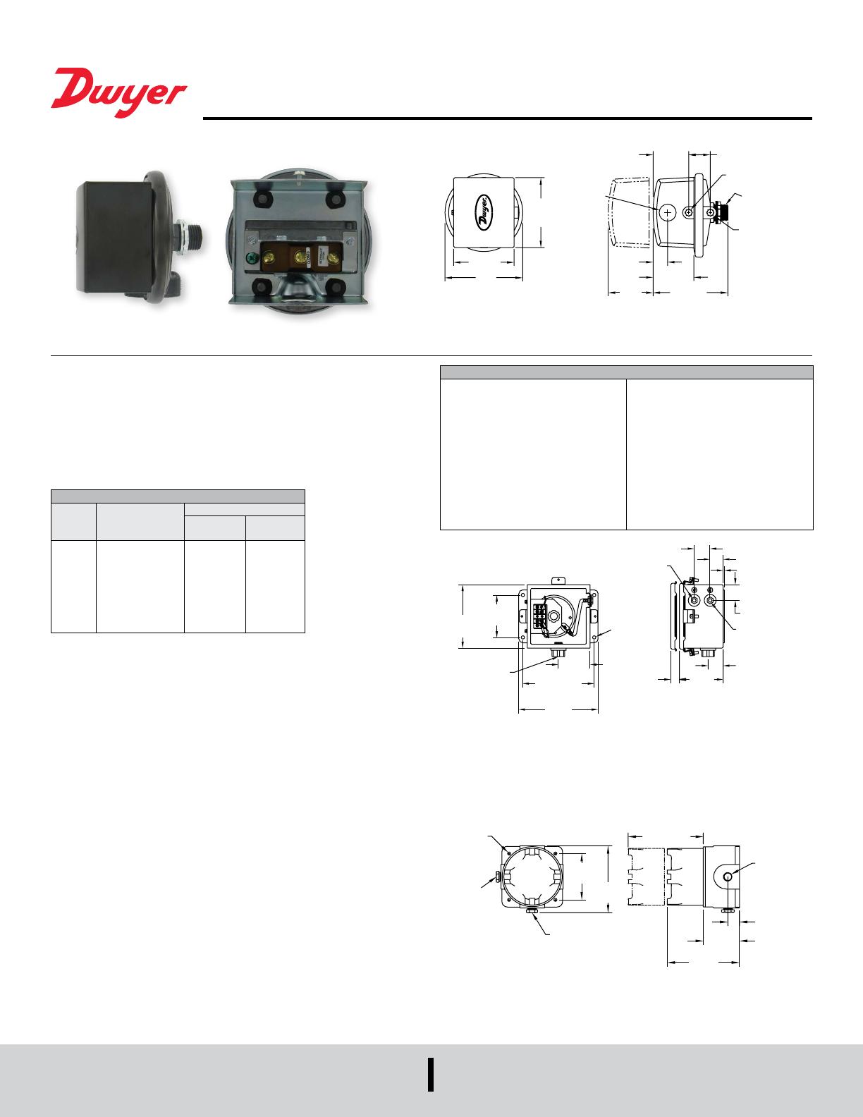
Construction and dimensions. Series 1823 pressure switches.
Model 1823 pressure switch.
UL and CSA Listed, FM and
CENELEC approved.
One of our most popular pressure switches. Combines small size and low price with
2% repeatability for enough accuracy for all but the most demanding applications.
Set point adjustment inside the mounting switch on one side of a wall or panel with
adjustment easily accessible on the opposite side.
*Model 1823 shown; (1823 replaces 1820, 1821 and 1822 which are similar).
Environmental (MIL) Switch
Unlisted Model 1820 can be furnished with special snap switch sealed against the
environment for high humidity and/or for government applications. Similar to standard
Model 1823 except dead band is slightly greater. Specify Model 1820 (Range No.)
“MIL” in ordering.
INSTALLATION
1. Select a location free form excessive vibration and where oil or water will not drip
upon the switch. See special housings for unusual conditions.
2. While not required, positioning the pressure connections down is recommended.
Mount the switch with the diaphragm in a vertical plane. Switch with the diaphragm
in a vertical plane. Switch must be recalibrated for each change in operating
position.
3. Connect switch to source of pressure differential. Metal tubing with 1/4˝ O.D. is
recommended but any tubing system which will not restrict the air ow is
satisfactory. Note that the low pressure connection may be made to the 1/2˝ spud
at the back of the switch if desired. If so connected, drill 1/16˝ diameter holes in the
Spring Retainer ange and the head of Adjustment Screw to provide opening to the
switch interior and plug the other low pressure connection.
4. Electrical connections to the standard single pole, double throw snap switch are
provided by means of screw terminals marked “common”, “norm open”, and “norm
closed”. The normally open contacts close and the normally closed contact open
when pressure increases beyond the set point.
5. Switch loads should not exceed the maximum specied current rating of 15 amps
resistive. Switch capabilities decrease with high load inductance or rapid cycle
rates. Whenever and application involves one or more of these factors, the user
may nd it desirable to limit the switched current to 10 amps or less in the interest
of prolonged switch life.
ADJUSTMENT
1. If the switch has been factory preset, check the set-point before placing in service
to assure it has not shifted in transit.
2. If switching has not been preset or it is desired to change the point, observe the
following procedure:
a. To adjust the set point turn the slotted Adjustment Screw clockwise to increase
the set point and counterclockwise to decrease the set point.
b. The following is a recommended procedure for calibrating or checking
calibration: Use a “T” assembly with three rubber tubing leads, all as short as
possible and the entire assembly offering minimum ow restriction. Run
one lead to the pressure switch, another to a manometer of known accuracy
and appropriate range, and apply pressure through the third tube. Make nal
approach to the set point slowly. Note the manometer and pressure switch will
have different response characteristics due to different internal volumes,
lengths of tubing, oil drainage, etc. Be certain switch is checked in position it will
assume in use, i.e. vertical, horizontal, etc.
SPECIFICATIONS
Service: Air and non-combustible,
compatible gases.
Wetted Materials: Consult factory.
Temperature Limits: -30 to 180°F (-34
to 82.2°C). 1823-00, -20 to 180°F (-28.9
to 82.2°C).
Pressure Limits: 10 psig (68.95 kPa)
continuous, 25 psig (172.4 kPa) surge.
Switch Type: Single-pole double-throw
(SPDT).
Repeatability: ±2%.
Electrical Rating: 15 A @ 120-480 VAC,
60 Hz. Resistive 1/8 HP @125 VAC, 1/4
HP @ 250 VAC, 60 Hz. De-rate to 10 A
for operation at high cycle rates.
Electrical Connections: 3 screw type,
common, normally open and normally
closed.
Process Connections: 1/8˝ female
NPT.
Mounting Orientation: Diaphragm in
vertical position. Consult factory for
other position orientations.
Set Point Adjustment: Screw type
inside mounting spud.
Weight: 1 lb, 5 oz (595 g).
Agency Approvals: CE, UL, CSA, FM.
MODEL CHART
Model
Operating Range,
in w.c.
Approximate Dead Band
At Min.
Set Point
At Max.
Set Point
1823-00
1823-0
1823-1
1823-2
1823-5
1823-10
1823-20
1823-40
1823-80
0.07 to 0.22
0.15 to 0.5
0.3 to 1.0
0.5 to 2.0
1.5 to 5.0
2.0 to10
3 to 22
5 to 44
9 to 85
0.05
0.06
0.08
0.10
0.14
0.18
0.35
0.56
1.30
0.05
0.06
0.08
0.12
0.28
0.45
0.70
1.10
3.0
Weatherproof Enclosure
16 ga. steel enclosure for unusually wet or oily conditions. Withstands 200 hour salt
spray test. Gasketed cover. Weight 5-1/2 lb (2.5 kg). Switch must be installed at
factory. Specify “WP” in addition to switch catalog number.
Explosion-Proof Housing
Cast iron base and aluminum dome cover. Approximate weight 7-1/2 lb (3.4 kg).
Specify “EXPL” in addition to switch catalog number. Rated Class I, Groups C & D,
Div. 1. Class II, Groups E, F, & G, Div. 1.
1/8 FEMALE NPT
LOW PRESSURE
CONNECTION
1-1/4 [31.75]
3/32 [2.38]
1/8 FEMALE NPT
HIGH PRESSURE
CONNECTION
1-7/16
[36.53]
4-1/6
[103.19]
3/4
[19.05]
CLEARANCE FOR
COVER REMOVAL
Ø5/16 [7.94]
MOUNTING
HOLES TYP
4 PLACES
SQ
4 [101.60]
TYP
1/2 FEMALE
NPT CONDUIT
CONNECTION
3
[76.20]
6-3/4
[171.45] TYP
7-1/2
4X Ø.281
[7.14]
2X 4-1/4
[107.95]
2X 6-1/8
[155.58]
1/8 FEMALE NPT
LOW PRESSURE
CONNECTION
1/8 FEMALE
NPT HIGH
PRESSURE
CLEARANCE FOR
COVER REMOVAL
1/2 NPT
PROCESS
3X 1-1/16
[26.99]
3
[76.20]
6-5/8
DWYER INSTRUMENTS, INC.
P.O. BOX 373 • MICHIGAN CITY, INDIANA 46360, U.S.A.
Phone: 219/879-8000
Fax: 219/872-9057
www.dwyer-inst.com