Page is loading ...

September
1983
FORM:
OM-1540B
t6
0~
OWNERS
MANUAL
MILLER
ELECTRIC
MFG.
Co.
718
S.
BOUNDS
SI,
P.O.
Box
1079
APPLETON,
WI
54912
USA
Effective
With
Serial
No.
JD695160
MODEL
AUTOMATIC
2
SHUNT
CONTROL
HUB
AND
SPINDLE
WIRE
REEL
I.
ER
PRINTED
IN
U.S.A.
-

LIMITED
WARRANTY
EFFECTIVE:
JUNE
1.
1979
This
warranty
supersedes
all
previous
MILLER
warranties
and
is
ex
clusive
with
no
other
guarantees
or
warranties
expressed
or
implied.
LIMITED
WARRANTY-Subject
to
the
terms
and
conditions
As
a
matter
of
general
policy
only,
Miller
may
honor
claims
hereof,
Miller
Electric
Mfg.
Co.
Appleton,
Wisconsin
warranls
submitted
by
the
original
user
within
the
foregoing
periods.
to
its
Distributor/Dealer
that
all
new
and
unused
Equipment
*
(
furnished
by
Miller
is
free
from
defect
in
workmanship
and
In
the
case
of
Millers
breach
of
warranty
or
any
other
duty
f
material
as
of
the
time
and
place
of
delivery
by
Miller.
No
war-
with
respect
to
the
quality
of
any
goods,
the
exclusive
remedies
ranty
is
made
by
Miller
with
respect
to
engines,
trade
ac-
therefore
shall
be,
at
Millers
option
Ii)
repair
or
(2)
replacement
~
cessories
or
other
items
manufactured
by
others.
Such
or,
where
authorized
in
writing
by
Miller
in
appropriate
cases,
131
engines,
trade
accessories
and
other
items
are
sold
sublect
to
the
reasonable
cost
of
repair
or
replacement
at
an
authorized
the
warranties
of
their
respective
manufacturers,
if
any
.
All
Miller
service
station
or
14)
payment
of
or
credit
for
the
purchase
engines
are
warranted
by
their
manutacturer
for
one
year
from
price
Iless
reasonable
depreciation
based
upon
actual
usel
upon
date
of
original
purchase,
return
of
the
goods
at
Customers
risk
and
expense.
Upon
receipt
of
notice
of
apparent
defect
or
failure,
Miller
shall
instruct
the
clai-
Except
as
specified
below,
Millers
warranty
does
not
apply
mant
on
the
warranty
claim
procedures
to
be
followed,
d
to
components
having
normal
useful
life
of
less
than
one
(1)
year,
such
as
spot
welder
tips,
relay
and
contactor
points,
ANY
EXPRESS
WARRANTY
NOT
PROVIDED
HEREIN
AND
~
MILLERMATIC
parts
that
come
in
contact
with
the
welding
ANY
IMPLIED
WARRANTY,
GUARANTY
OR
REPRESENTA-
?
wire
including
nozzles
and
nozzle
insulators
where
failure
does
TION
AS
TO
PERFORMANCE,
AND
ANY
REMEDY
FOR
not
result
from
defect
in
workmanship
or
material.
BREACH
OF
CONTRACT
WHICH,
BUT
FOR
THIS
PROVISION,
~
MIGHT
ARISE
BY
IMPLICATION,
OPERATION
OF
LAW,
Miller
shall
be
required
to
honor
warranty
claims
on
war-
CUSTOM
OF
TRADE
OR
COURSE
OF
DEALING,
INCLUDING
ranted
Equipment
in
the
event
of
failure
resulting
from
a
defect
ANY
IMPLIED
WARRANTY
OF
MERCHANTABILITY
OR
OF
within
the
following
periods
from
the
date
of
delivery
of
Equip-
FITNESS
FOR
PARTICULAR
PURPOSE,
WITH
RESPECT
TO
(
ment
to
the
original
user:
ANY
AND
ALL
EQUIPMENT
FURNISHED
BY
MILLER
IS
EX
CLUDED
AND
DISCLAIMED
BY
MILLER.
1.
Arc
welders,
power
sources
and
components
.
1
year
2.
Original
main
power
rectifiers
3
years
EXCEPT
AS
EXPRESSLY
PROVIDED
BY
MILLER
IN
Ilabor
-
1
year
onlyl
WRITING,
MILLER
PRODUCTS
ARE
INTENDED
FOR
3.
All
welding
guns
and
feeder/guns
90
days
ULTIMATE
PURCHASE
BY
COMMERCIAL/INDUSTRIAL
4.
All
other
Millermatic
Feeders
1
year
USERS
AND
FOR
OPERATION
BY
PERSONS
TRAINED
AND
5.
Replacement
or
repair
parts,
exclusive
of
labor
.
60
days
EXPERIENCED
IN
THE
USE
AND
MAINTENANCE
OF
3
6.
Batteries
6months
WELDING
EQUIPMENT
AND NOT
FOR
CONSUMERS
OR
CONSUMER
USE.
MILLER
WARRANTIES
DO
NOT
EXTEND
provided
that
Miller
is
notified
in
writing
within
thirty
(30)
days
TO,
AND
NO
RESELLER
IS
AUTHORIZED
TO
EXTEND
?
of
the
date
of
such
failure.
MILLERS
WARRANTIES
TO,
ANY
CONSUMER.
Sr
~,
Sr
Sr
Sr
~%
Sr
,,
!~,
Sr.
~x~
Sr..~x.
Sr
~?t,
Sr
~
Sr
Sr

Dec.
4,
1986
FORM:
OM-1540B
ERRATA
SHEET
After
this
manual
was
printed,
refinements
in
equipment
design
occurred.
This
sheet
lists
exceptions
to
data
appearing
I~iter
in
this
manual.
AMENDMENT
TO
SECTION
6
-
MAINTENANCE
&
TROUBLESHOOTING
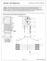
Amend
Figure
6
-
1.
Circuit
Diagram
See
page
2
for
circuit
diagram.
Dia.
Part
Replaced
**
Mkgs.
No.
With
Description
Quantity
3-86
091
627
007
158
KNOB,
pointer
2
5-
C:R50,51
027 810 095
521
RELAY,
enclosed
24
volts
dc
4PDT
2
5-
R53,57
605
912
039
331
RESISTOR,carbonfilm0.25watt4.7Kohm
2
5-
R54,56,59,60
605
911
035
827
RESISTOR,
carbon
film
0.25
watt
10K
ohm
4
5-
R55,58
605 909
035
886
RESISTOR,
carbon
film
0.25
watt
22K
ohm
2
6-
R8
030
944
110
429
POTENTIOMETER,cermetl
turn
0.5
watt5K
ohm
1
8-7
PC3
082
881
095
775
CIRCUIT
CARD,
meter
converter(Eff
w/JE817807)
1
8-
C58,59,64-67,70
073 739
073
739
CAPACITOR
(qty
chg)
7
8-
1)50-58
026
202 026
202
DIODE
(qty
chg)
9
8-
1C50,51
082
506
082
506
IC,
linear
536
(description
chg)
2
8-
R51
039
352
052
151
POTENTIOMETER,
cermet25
turn
0.5
watt
lOOK
ohm
1
8-
R56
039 360
082
179
POTENTIOMETER,
cermet
25
turn
0.5
watt
25K
ohm
1
8-
R58
035
848 082
178
POTENTIOMETER,
cermet25
turn
0.5
watt
10K
ohm
1
8-
VR5O
081
832
081
832
IC,
linear
78M15
(description
chg)
1
8-
VR51
046
932
046
932
IC,
linear
7915
(description
chg)
1
8-
RC5O
079 795
079
795
TERMINAL,
header
13
pin
(dia
mkg
added)
1
9-10
072 369
092
989
SUPPORT,
spindle
(consisting
of)
1
070 634
.
LABEL,
warning
electric
shock
can
kill
1
I~63,64
035
823
RESISTOR,
carbon
film
0.25
watt
100
ohm
2
092
648
RESISTOR,
carbon
film
0.25
watt
zero
ohm
3
**First
digit
represents
page
no
-
digits
following
dash
represent
item
no.
BE
SURE
TO
PROVIDE
MODEL
AND
SERIAL
NUMBER
WHEN
ORDERING
REPLACEMENT
PARTS.
~~LE
COPY
flP~URN
TO
FOLCER

TAXER
8
s
PC4
RC7~7
–10
,~
,~
~H
I
PLG5Q
I
1~02~
i~
AT
I
~6l
~<<
~-<E~
L
_~
*F02
___________________
OPrIONAL
PRE-PLI3H
-o
~-
1JRCo
REMOTE
PENDANT
(OPTIONAL)
50
INCA-UP
INCH
CRE..j
(PR4
CR2
-a
56(1)
INCH-UP
~p2
Th
POE-FLUX
-6;;;~
58
c0510
I~
YpLOIX
a
481
~
<-3
PEG,5
?~6
~~~4~____
~
~CR5oa
\~5
~I~5
~2a
OPTIONAL
T~l0y
2~pI
8F~
r
)>
JPLGI0t~~O~PLGI0
2
L
j4
SHE
~yPLG
/0
I-I
85
,
PG3
E
ERG
REMOVE
JUMPERS
FOR
REMOTE
PENDANT
P056
A
058
B0~.__REMOVE
FOR
RUN-IN
OPTION
C
~
66
DO.
-
REMOVE
FOR
POST
FLOW
OPTION
E0
80
F
0.81
)___REMOVE
FOR
RUN-IN
OPTION
_________
0082
5083
10(0
Lo/l
aux,
(4012
CONTACTS
0074
0
01
0
w
(40700
BOARD
O~F
A0
START
REMOTE
CR
START
-o--~4--
~
~H
PR2
STOP
o~n
H
.~~0__.__2L__.~.1
~
~
CR5
37
OAT
INCH
UP
_o-~
INCH
DOWN
P.~GI0
INC/I
IX)WN
I~
~
8LIT
INCH
UP
RCA
RE7
GAS
VALVEIOPTI
~VALVEIOPTI-
-
PLOIXI
-_
PLC7
OCT
~
~
~
~
66
-
-
M~>~.)~~
2>>
~87
PLGT
GX~.)~4
la>>,~
RCI3
<~~---<<
V
N
>>~>
6)~--(E---O
TO
WOOR
2
1
B
PC,
~
~
CR.t~~
~e..
(r~)
~
~T
I
T
T
I
I
I31PLG9
1
3
I
(6
20
21
IS
I?
jPEGIS
141
~tiL
I
r~i
06
0
CRATER
TIME
110
PC2
C
I
RC3I__,~~
~
I
1
621
60
1-
--1
Y
Y
YPLGIT-_QPTIONA.
53
I
PLG15AZ
jO?
~DS
I
WITH
POSTELOW
I
I
68~-~~
CW
j~
PLG,SA
PLG1RA
I
I
$
lRIp~~
AR
A2
CR5
fl~jE~o
CW1J1
j1CW
_________
j~jIo:7Io:aL,
O~
O~I
B
,
~
i~1
41PLG1515
OprIONaL,
CR5
~~
~
Circuit
Diagram
No.
C-091
883-B
Figure
6
-
1.
Circuit
Diagram

J~1~ary
31,1986
FORM:
OM-1540B
ERRATA
SHEET
After
this
rrianual
was
printed,
refinements
in
equipment
design
occurred.
This
sheet
lists
exceptions
to
data
appearing
later
in
this
manual.
AMENDMENT
TO
SECTION
6
-
MAINTENANCE
&
TROUBLESHOOTING
Amend
Figure
6
-
1-.
Circuit
Diagram
See
page
2
for
circuit
diagram.
Dia.
Part
Replaced
**
Mkgs.
No.
With
Description
Quantity
5-
CR5O,51
027
810
095
521
RELAY,
enclosed
24
volts
dc
4PDT
2
5-
R53,57
605
912
039
331
RESISTOR,
carbon
film
0.25
watt4.7K
ohm
2
5-
R54,56,59,60
605
911
035
827
RESISTOR,
carbon
film
0.25
watt
10K
ohm
4
5-
R55,58
605 909
035
886
RESISTOR,
carbon
film
0.25
watt22K
ohm
2
8-7
PC3
082
881
095
775
CIRCUIT
CARD,
meter
converter
(Eff
w/JE817807)
1
8-
C58,59,64-67,70
073
739
073 739
CAPACITOR
(qtychg)
7
8-
D50-58
026 202
026
202
DIODE
(qty
chg)
9
8-
lC5O,51
082
506
082
506
IC,
linear
536
(description
chg)
2
8-
R51
039
352
052
151
POTENTIOMETER,
cermet25turn0.5wattlO0Kohm
1
8-
R56
039 360
082
179
POTENTIOMETER,
cermet25
turn
0.5
watt
25K
ohm
1
8-
R58
035
848
082
178
POTENTIOMETER,
cermet
25
turn
0.5
watt
10K
ohm
1
8-
VR5O
081
832
081
832
IC,
linear78Ml5(descriptionchg)
1
8-
VR51
046 932 046
932
IC,
linear
7915
(description
chg)
1
8-
RC5O
079
795
079
795
TERMINAL,
header
13
pin
(dia
mkg
added)
1
9-10
072 369
092 989
SUPPORT,
spindle
(Consisting
of)
1
070
634
.
LABEL,
warning
electric
shock
can
kill
1
R63,64
035
823
RESISTOR,
carbon
film
0.25
watt
100
ohm
2
092
648
RESISTOR,
carbon
film
0.25
watt
zero
ohm
3
**First
digit
represents
page
no
-
digits
following
dash
represents
item
no.
BE
SURE TO
PROVIDE
MODEL
AND
SERIAL
NUMBER
WHEN
ORDERING
REPLACEMENT
PARTS.
~
~o~Y
RETURN
TO
FOLDER

ARCA
12
9
~
~
~~PIG~
4
8
S/l~9CIa
RC,A7
–10
~ii1-1
~
~
~
24ooc~~~LooTrJ
~-
~
c~.~r_-4~2j1L
~
6
j
AC
,~,
OEJ_
0<<
~
START
REIIADE
J
2ti
~34CR~
I
PeZ
fi
fi
~C6
PLO:
L
i
r~3
CR5
r
~
PLUS
PLG9
30
'
'
S
(A)
~--J
PRO-FLUB
RCp
REMOTE
PENDANT
(OPTIONAL,
CR3
IA)
INCH-UP
5?
NCR
CR2
CR
-o---
5R~D
INCIIT,P
CR2
i~7@
POE-FLUX
~
56
0P950
f
RCA
AC,
~ClE
<~-
GAS
VALVEIOPTI
~RAALVE,OPT~9~
25
PLG,4
~
31
TO
GUP
IN
SPEED
PLO7
RC1
PC3
RCA
C
0Y>~>
>>~~~~_?J
-
M--~.)~
(2>>
~7
PLO
o>>)~~
~
90
E--<<
5
5
)>~)~
~>><~~
TO
WORE
21
0
5
1
PtGn~
A~dIo
~6
f1>1~L<.5
I
ZCRS0a
~
~
W
LW
$R
4
~
~_~
s~I~
CRATER
INCH
I
6(0(9
A
jea
~
SPEE:~
~
I(~C~fl
:;~nt~
R24
OPTIONAL
SC1,
-
.----
~0~~
0
0
PLO
C1~~~i
~
>E
00
ERR
~32
HO~
JR~5
50Sf
REMOVE
JUMPERS
FOR
REMOTE
PENDANT
MOV~
6(052
P056
BO67_REMOVE
FOR
RAN-IN
OPTION
REMOVE
FOR
POST
FLOW
OPTION
CR60
F
081
3_REMOVE
FOR
RUN-IN
OPTION
OR_Ba
HO
83
(010
LOU
AOL
MRI2
CONTACTS
N
0/3
P0/4
0
UI
0 w
M
~CR4
L
I
/
AFR
-2
OPTIONAL
A~
1
)~I~
CR3
;
r~i
I
~ER3
RC1~U,
1
.
I~L
A
0
<E
43
1
CR~1s
~
LW
I
~
YPLGI5
/
681
~
MOVOR
BOARD
o~
(((CHAP
?54
~
INCH
UP
-
RCA
PCI
,J..\
,i\
CR-t~I~
8
~o)
~)
5T
I
T
~r
~~>-~2T0
I
13~
PLO0
3
1
6
20
21
5
IT
~~-~~u11
~j~~0~j72
I
I~1
I
PURNOACIA
DO
S
CRATER
TIME
PLO
(~)
a)
A
~>7~02TL
T
T
~CR1~1
L~2TM
L____~
_~i
......J
~
T35
~
l.j,6C50
I
621
601
1.__._IYYYPLGIT..OP,ONAL
3
PLGISA2
I
09
I
I
WITII
POSTFLOW
I
I
68
--~
I
CO
J
I
P~G,5A
6(0,6
I
*JHIPRE~
I
~
R2
CR5
1,~jFLUU
CW1.L1
I~I
I
I
r11
I0I9~,OP1,ONAL1
I
CR,
~
CR
J
~
I
~
+
+~RANIN
I
~
~i
i.~2I
41PLG/S15IOPTIONGOI
CR5
–.......0R5
I
i
Circuit
Diagram
No.
C-091
883-B
Figure
6
-
1.
Circuit
Diagram

ERRATA
SHEET
After
this
manual
was
printed,
refinements
in
equipment
design
occurred.
This
appearing
later
in
this
manuaL.
-
AMENDMENT
TO
SECTION
6
-
MAINTENANCE
&
TROUBLESHOOTING
Amend
Figure
6
-
1.
Circuit
Diagram
4
I
a)
a)
C.)
0
z
E
a
a
4-
C.,
C.)
w
0
LL
w
E
I
C.)
I
April
25,
1985
FORM:
OM-1540B
sheet
Lists
exceptions
to
data

Dia.
Part
Replaced
**
Mkgs.
No.
With
Description
Quantity
8-7
PC3
082
881
095
775
CIRCUIT
CARD,
meter
converter
(Eff
w/JE817807)
1
8-
C58,59,64-67,70
073 739
073
739
CAPACITOR
(qty
chg)
7
8-
D50-58
026
202
026
202
DIODE
(qty
chg)
9
8-
1C50,51
082
506
082
506
IC,
linear
536
(description
chg)
2
8-
R51
039
3.52
052
151
POTENTlOMETER,cerm~t25turn0.5watt100Kohm
1
8-
R56
039 360 082
179
POTENTIOMETER,
cermet
25
turn
0.5
watt
25K
ohm
1
8-
R58
035 848 082
178
POTENTIQMETER,
cermet25
tUrn
0.5
watt
10K
ohm
1
8-
VR5O
081
832
081
832
IC,
linear
78M15
(description
chg)
1
8-
VR51
046
932
046
932
IC,
linear
7915
(description
chg)
1
8-
RC5O
079
795
079
795
TERMINAL,
header
13
pin
(dia
mkg
added)
1
9-10
072
369
092
989
SUPPORT,
spindle
(consisting
of)
1
.
070
634
.
LABEL,
warning
electric
shock
can
kill
1
R63,64
035 823
RESISTOR,
carbon
film
0.25
watt
100
oh~m
2
092
648
RESISTOR,
carbon
film
0.25
watt
zero
ohm
3
**First
digit
represents
page
no
-
digits
following
dash
represents
item
no.
BE
SURE
TO
PROVIDE
MODEL
AND
SERIAL
NUMBER
WHEN
ORDERING
REPLACEMENT
PARTS.
OM-1540B
Page
2

TABLE
OF
CONTENTS
Section
No.
Page
No.
SECTION
1
-
SAFETY
RULES
FOR
OPERATION
OF
ARC
WELDING
POWER
SOURCE
1
-
1.
Introduction
1
1
-
2.
General
Precautions
1
1
-3.
Arc
Welding
4
1
-
4.
Standards
Booklet
Index
5
SECTION
2
-
INTRODUCTION
2
-
1.
General
Information
And
Safety
7
2
-
2.
Receiving-Handling
7
2
-
3.
Description
7
SECTION
3
-
INSTALLATION
3-1.
Location
8
3
-
2.
Remote
Pendent
Control
8
3
-
3.
Flux
Hopper
With
Automatic
Valve
8
3
-
4.
Shielding
Gas
Connections
8
3
-5.
Water
Connections
9
3
-
6.
Auxiliary
Relay
Contacts
9
3-7.
Hub
And
SpindleAssembly
Installation
10
3
-
8.
Installation
Of
Spool-Type
Wire
10
3
-
9.
Installation
of
Reel-Type
Wire
10
3-10.
Installation
of
Wire
Reel
10
3-11.
Weld
Control
Interconnections
11
SECTION
4
-
OPERATOR
CONTROLS
4
-
1.
Power/Emergency
Stop
Switch
13
4-2.
PilotLight
13
4-3.
StartPushButton
13
4
-
4.
Stop
Push
Button
13
4
-
5.
Preflux
Push
Button
13
4-6.
JogUpPushButton
13
4
-
7.
Jog
Down
Push
Button
13
4
-
8.
Weld
Voltage
Control
13
4
-
9.
Weld
Wire
Speed
Control
14
4-10.
Pre-FIux
Time
Control
14
4-11.
RunlnSpeedControl
14
4-12.
Run
In
Voltage
Control
14
4-13.
RunlnTimeControl
14
4-14.
Crater
Voltage
Control
14
4-15.
Crater
&
Jog
Speed
Control
14
4-16.
Crater
Time
Control
14
4-17.
BurnbackTimeControl
14
4-18.
Post-FlowTime
Control
14
4-19.
Meters
15
4-20.
Overload
Protection
15
SECTION
5
-
SEQUENCE
OF
OPERATION
5-1.
Weld
Cycle
Events
15
5
-2.
Submerged
Arc
Welding
15
5-3.
Gas
Metal-Arc
Welding
15
5
-
4.
Shutting
Down
15
SECTION
6
-
MAINTENANCE
&
TROUBLESHOOTING
6
-
1.
Inspection
And
Upkeep
16
6-2.
General
16
6
-
3.
Troubleshooting
Chart
16


SECTION
1
-
SAFETY
RULES
FOR
OPERATION
OF
ARC
WELDING
POWER
SOURCE.
1-1.
INTRODUCTION
-
We
learn
by
experience.
Learning
safety
through
personal
experience,
like
a
child
touching
a
hot
stove
is
harmful,
wasteful,
and
un
wise.
Let
the
experience
of
others
teach
you.
Safe
practices
developed
from
experience
in
the
use
of
welding
and
cutting
are
described
in
this
manual.
Research,
development,
and
field
experience
have
evolved
reliable
equipment
and
safe
installation,
opera
tion,
and
servicing
practices.
Accidents
occur
when
equipment
is
improperly
used
or
maintained.
The
reason
for
the
safe
practices
may
not
always
be
given.
Some
are
based
on
common
sense,
others
may
require
technical
volumes
to
explain.
It
is
wiser
to
follow
the
rules.
Read
and
understand
these
safe
practices
before
at
tempting
to
install,
operate,
or
service
the
equipment.
Comply
with
these
procedures
as
applicable
to
the
par
ticular
equipment
used
and
their
instruction
manuals,
for
personal
safety
and
for
the
safety
of
others.
Fadure
to
Dbserve
these
safe
practices
may
cause
serious
injury
or
death.
When
safety
becomes
a
habit,
the
equipmont
can
be
used
with
confidence.
These
safe
practices
are
divided
into
two
Sections:
1
-
General
Precautions,
common
to
arc
welding
and
cutting;
and
2
-
Arc
Welding
(and
Cutting)
(only).
Reference
standards:
Published
Standards
on
safety
are
also
available
for
additional
and
more
complete
pro
cedures
thaii
those
given
in
this
manual.
They
are
listed
in
the
Stan~ards
Index
in
this
manual.
ANSI
Z49.1
is
the
most
complete.
The
National
Electrical
Code,
Occupational
Safety
and
Health
Administration,
local
industrial
codes,
and
local
inspection
raquirements
also
provide
a
basis
for
equip
ment
install
~tion,
use,
and
service.
1-2.
GENERAL
PRECAUTIONS
Different
arc
welding
processes,
electrode
alloys,
and
fluxes
can
produce
different
fumes,
gases,
and
radiation
levels.
In
addition
to
the
information
In
this
manual,
be
sure
to
consult
flux
and
elec
trode
manufacturers
for
specific
technical
data
and
precautionary
measures
concerning
their
material.
A.
Burn
Prevention
Wear
protective
clothing
-
gauntlet
gloves
designed
for
use
in
welding,
hat,
and
high
safety-toe
shoes.
Button
shirt
collar
and
pocket
flaps,
and
wear
cuffless
trousers
to
avoid
entry
of
sparks
and
slag.
Wear
helmei~
with
safety
goggles
or
glasses
with
side
shields
underneath,
appropriate
filter
lenses
or
plates
(protected
by
clear
cover
glass).
This
is
a
MUST
for
welding
or
cutting,
(and
chipping)
to
protect
the
eyes
from
radiant
energy
and
flying
metal.
Replace
cover
glass
when
broken,
pitted,
or
spattered.
See
1-3A.2.
Avoid
oily
or
greasy
clothing.
A
spark
may
ignite
them.
Hot
metal
such
as
electrode
stubs
and
workpieces
should
never
be
handled
without
gloves.
Medical
first
aid
and
eye
treatment.
First
aid
facilities
and
a
qualified
first
aid
person
should
be
available
for
each
shift
unless
medical
facilities
are
close
by
for
im
mediate
treatment
of
flash
burns
of
the
eyes
and
skin
burns.
Ear
plugs
should
be
worn
when
working
on
overhead
or
in
a
confined
space.
A
hard
hat
should
be
worn
when
others
work
overhead.
Flammable
hair
preparations
should
not
be used
by
per
sons
intending
to
weld
or
cut.
B.
Toxic
Fume
Prevention
Severe
discomfort,
illness
or
death
can
result
from
fumes,
vapors,
heat,
or
oxygen
enrichment
or
depletion
that
welding
(or
cutting)
may
produce.
Prevent
them
with
adequate
ventilation
as
described
in
ANSI Stan
dard
Z49.1
listed
1
in
Standards
index.
NEVER
ventilate
with
oxygen.
Lead
-,
cadmium
-,
zinc
-,
mercury
-,
and
beryllium
-
bearing
and
similar
materials,
when
welded
(or
cut)
may
produce
harmful
concentrations
of
toxic
fumes.
Ade
quate
local
exhaust
ventilation
must
be
used,
or
each
person
in
the
area
as
well
as
the
operator
must
wear
an
air-supplied
respirator.
For
beryllium,
both
must
be
us
ed.
Metals
coated
with
or
containing
materials
that
emit
toxic
fumes
should
not
be
heated
unless
coating
is
removed
from
the
work
surface,
the
area
is
well
ven
tilated,
or
the
operator
wears
an
air-supplied
respirator.
Work
in
a
confined
space
only
while
it
is
being
ven
tilated
and,
if
necessary,
while
wearing
an
air-supplied
respirator.
Gas
leaks
in
a
confined
space
should
be
avoided.
Leaked
gas
in
large
quantities
can
change
oxygen
con
centration
dangerously.
Do
not
bring
gas
cylinders
into
a
confined
space.
Leaving
confined
space,
shut
OFF
gas
supply
at
source
to
prevent
possible
accumulation
of
gases
in
the
space
if
downstream
valves
have
been
accidently
opened
or
left
open.
Check
to
be
sure
that
the
space
is
safe
before
re-entering
it.
Vapors
from
chlorinated
solvents
can
be
decomposed
by
the
heat
of
the
arc
(or
flame)
to
form
PHOSGENE,
a
OM-1540
Page
1

highly
toxic
gas,
and
other
lung
and
eye
irritating
pro
ducts.
The
ultraviolet
(radiant)
energy
of
the
arc
can
also
decompose
trichloroethylene
and
per
chloroethylene
vapors
to
form
phosgene.
DO NOT
WELD
or
cut
where
solvent
vapors
can
be
drawn
into
the
welding
or
cutting
atmosphere
or
where
the
radiant
energy
can
penetrate
to
atmospheres
containing
even
minute
amounts
of
trichloroethylene
or
per
chloroethylene.
C.
Fire
and
Explosion
Prevention
Causes
of
fire
and
explosion
are:
combustibles
reached
by
the
arc,
flame,
flying
sparks,
hot
slag
or
heated
material;
misuse
of
compressed
gases
and
cylinders;
and
short
circuits.
BE
AWARE
THAT
flying
sparks
or
falling
slag
can
pass
through
cracks,
along
pipes,
through
windows
or
doors,
and
through
wall
or
floor
openings,
out
of
sight
of
the
goggled
operator.
Sparks
and
slag
can
fly
35
feet.
To
prevent
fires
and
explosion:
Keep
equipment
clean
and
operable,
free
of
oil,
grease,
and
(in
electrical
parts)
of
metallic
particles
that
can
cause
short
Circuits.
If
combustibles
are
in
area,
do
NOT
weld
or
cut.
Move
the
work
if
practicable,
to
an
area
free
of
combustibles.
Avoid
paint
spray
rooms,
dip
tanks,
storage
areas,
von
tilators.
If
the
work
cannot
be
moved,
move
com
bustibles
at
least
35
feet
away
out
of
reach
of
sparks
and
heat;
or
protect
against
ignition
with
suitable
and
snug-fitting,
fire-resistant
covers
or
shields.
Walls
touching
combustibles
on
opposite
sides
should
not
be
welded
on
(or
cut).
Walls,
ceilings,
and
floor
near
work
should
be
protected
by
heat-resistant
covers
or
shields.
Fire
watcher
must
be
standing
by
with
suitable
fire
ex
tinguishing
equipment
during
and
for
some
time
after
welding
or
cutting
if:
a.
appreciable
combustibles
(including
building
construction)
are
within
35
feet
b.
appreciable
combustibles
are
further
than
35
feet
but
can
be
ignited
by
sparks
c.
openings
(concealed
or
visible)
in
floors
or
walls
within
35
feet
may
expose
com
bustibles
to
sparks
d.
combustibles
adjacent
to
walls,
ceilings,
roofs,
or
metal
partitions
can
be
ignited
by
radiant
or
conducted
heat.
Hot
work
permit
should
be
obtained
before
operation
to
ensure
supervisors
approval
that
adequate
precautions
have
been
taken.
After
work
is
done,
check
that
area
is
free
of
sparks,
glowing
embers,
and
flames.
An
empty
container
that
held
combustibles,
or
that
can
produce
flammable
or
toxic
vapors
when
heated,
must
OM-1
540
Page
2
never
be
welded
on
or
cut,
unless
container
has
first
been
cleaned
as
described
in
AWS
Standard
A6.O,
listed
3
in
Standards
index.
This
includes:
a
thorough
steam
or
caustic
cleaning
(or
a
solvent
or
water
washing,
depending
on
the
com
bustibles
solubility)
followed
by
purging
and
inerting
with
nitrogen
or
carbon
dioxide,
and
using
protective
equipment
as
recommended
in
A6.O.
Waterfilling
just
below
working
level
may
substitute
for
inerting.
A
container
with
unknown
contents
should
be
cleaned
(see
paragraph
above).
Do
NOT
depend
on
sense
of
smell
or
sight
to
determine
if it
is
safe
to
weld
or
cut.
Hollow
castings
or
containers
must
be
vented
before
welding
or
cutting.
They
can
explode.
Explosive
atmospheres.
Never
weld
or
cut
where
the
air
may
contain
flammable
dust,
gas,
or
liquid
vapors
(Such
as
gasoline).
D.
Compressed
Gas
Equipment
Standard
precautions.
Comply
with
precautions
in
this
manual,
and
those
detailed
in
CGA
Standard
P-i,
PRECAUTIONS
FOR
SAFE
HANDLING
OF
COMPRESSED
GASES
IN
CYLINDERS,
listed
6
in
Standards
index.
1.
Pressure
Regulators
Regulator
relief
valve
is
designed
to
protect
only
the
regulator
from
overpressure;
it
is
not
intended
to
protect
any
downstream
equipment.
Provide
such
protection
with
one
or
more
relief
devices.
Never
connect
a
regulator
to
a
cylinder
containing
gas
other
than
that
for
which
the
regulator
was
designed.
Remove
faulty
regulator
from
service
immediately
for
repair
(first
close
cylinder
valve).
The
following
symptoms
indicate
a
faulty
regulator:
Leaks
-
if
gas
leaks
externally.
Excessive
Creep
-
if
delivery
pressure
continues
to
rise
with
downstream
valve
closed.
Faulty
Gauge
-
if
gauge
pointer
does
not
move
off
stop
pin
when
pressurized,
nor
returns
to
stop
pin
after
pressure
release.
Repair.
Do
NOT
attempt
repair.
Send
faulty
regulators
for
repair
to
manufacturers
designated
repair
center,
where
special
techniques
and
tools
are
used
by
trained
personnel.
2.
Cylinders
Cylinders
must
be
handled
carefully
to
prevent
leaks
and
damage
to
their
walls,
valves,
or
safety
devices:
Avoid
electrical
circuit
contact
with
cylinders
in
cluding
third
rails,
electrical
wires,
or
welding
cir
cuits.
They
can
produce
short
circuit
arcs
that
may
lead
to
a
serious accident.
(See
1-3C.)

ICC
or
DOT
marking
must
be
on
each
cylinder.
It
is
an
assurance
of
safety
when
the
cylinder
is
properly
handled.
Identifying
gas
content.
Use
only
cylinders
with
name
of
gas
marked
on
them;
do
not
rely
on
color
to
identify
gas
content.
Notify
supplier
if
unmarked.
NEVER
DEFACE
or
alter
name,
number,
or
other
markings
on
a
cylinder.
It
is
illegal
and
hazardous.
Empties:
Keap
valves
closed,
replace
caps
securely;
mark
MT;
keep
them
separate
from
FULLS
and
return
promptly.
Prohibited
use.
Never
use
a
cylinder
or
its
contents
for
other
than
il:s
intended
use,
NEVER
as
a
support
or
roller.
Locate
or
se~ure
cylinders
so
they
cannot
be
knocked
over.
Passageways
and
work
areas.
Keep
cylinders
clear
of
areas
where
they
may
be
struck.
Transporting
cylinders.
With
a
crane,
use
a
secure
sup
port
such
as
a
platform
or
cradle.
Do
NOT
lift
cylinders
off
the
ground
by
their
valves
or
caps,
or
by
chains,
slings,
or
magnets.
Do
NOT
expose
cylinders
to
excessive
heat,
sparks,
slag,
and
flame,
etc.
that
may
cause
rupture.
Do
not
allow
contenl:s
to
exceed
130F.
Cool
with
water
spray
where
such
exposure
exists.
Protect
cylinders
particularly
valves
from
bumps,
falls,
falling
objecis,
and
weather.
Replace
caps
securely
when
moving
cylinders.
Stuck
valve.
Do
NOT
use
a
hammer
or
wrench
to
open
a
cylinder
valve
that
can
not
be
opened
by
hand.
Notify
your
supplier,
Mixing
gases.
Never
try
to
mix
any
gases
in
a
cylinder.
Never
refill
any
cylinder.
Cylinder
fittings
should
never
be
modified
or
exchang
ed.
3.
Hose
Prohibited
use.
Never
use
hose
other
than
that
designed
for
the
specif~ed
gas.
A
general
hose
identification
rule
is:
red
for
fuel
gas,
green
for
oxygen,
and
black
for
inert
gases.
Use
ferrules
or
clamps
designed
for
the
hose
(not
or
dinary
wire
or
other
substitute)
as
a
binding
to
connect
hoses
to
fittings.
No
copper
tuI~ing
splices.
Use
only
standard
brass
fit
tings
to
splice
hose.
Avoid
long
runs
to
prevent
kinks
and
abuse.
Suspend
hose
off
ground
to
keep
it
from
being
run
over,
stepped
on,
or
otherwise
damaged.
Coil
excess
hose
to
prevent
kinks
and
tangles.
Protect
hose
from
damage
by
sharp
edges,
and
by
sparks,
slag,
and
open
flame.
Examine
hose
regularly
for
leaks,
wear,
and
loose
con
nections.
Immerse
pressured
hose
in
water;
bubbles
in
dicate
leaks.
Repair
leaky
or
worn
hose
by
cutting
area
out
and
splic
ing
(1-203).
Do
NOT
use
tape.
4.
Proper
Connections
Clean
cylinder
valve
outlet
of
impurities
that
may
clog
orifices
and
damage
seats
before
connecting
regulator.
Except
for
hydrogen,
crack
valve
momentarily,
pointing
outlet
away
from
people
and
sources
of
ignition.
Wipe
with
a
clean
lintless
cloth.
Match
regulator
to
cylinder.
Before
connecting,
check
that
the
regulator
label
and
cylinder
marking
agree,
and
that
the
regulator
inlet
and
cylinder
outlet
match.
NEVER
CONNECT
a
regulator
designed
for
a
particular
gas
or
gases
to
a
cylinder
containing
any
other
gas.
Tighten
connections.
When
assembling
threaded
con
nections,
clean
and
smooth
seats
where
necessary.
Tighten.
If
connection
leaks,
disassemble,
clean,
and
retighten
using
properly
fitting
wrench.
Adapters.
Use
a
CGA
adapter
(available
from
your
sup
plier)
between
cylinder
and
regulator,
if
one
is
required.
Use
two
wrenches
to
tighten
adapter
marked
RIGHT
and
LEFT
HAND
threads.
Regulator
outlet
(or
hose)
connections
may
be
iden
tified
by
right
hand
threads
for
oxygen
and
left
hand
threads
(with
grooved
hex
on
nut
or
shank)
for
fuel
gas.
5.
Pressurizing
Steps:
Drain
regulator
of
residual
gas
through
suitable
vent
before
opening
cylinder
(or
manifold
valve)
by
turning
adjusting
screw
in
(clockwise).
Draining
prevents
ex
cessive
compression
heat
at
high
pressure
seat
by
allowing
seat
to
open
on
pressurization.
Leave
adjusting
screw
engaged
slightly
on
single-stage
regulators.
Stand
to
side
of
regulator
while
opening
cylinder
valve.
Open
cylinder
valve
slowly
so
that
regulator
pressure
in
creases
slowly.
When
gauge
is
pressurized
(gauge
reaches
regulator
maximum)
leave
cylinder
valve
in
following
position:
For
oxygen,
and
inert
gases,
open
fully
to
seal
stem
against
possible
leak.
For
fuel
gas,
open
to
less
than
one
turn
to
permit
quick
emergency
shutoff.
Use
pressure
charts
(available
from
your
supplier)
for
safe
and
efficient,
recommended
pressure
settings
on
regulators.
Check
for
leaks
on
first
pressurization
and
regularly
there-after.
Brush
with
soap
solution
(capful
of
Ivory
OM-1540
I~age3

Liquid*
or
equivalent
per
gallon
of
water).
Bubbles
in
dicate
leak.
Clean
off
soapy
water
after
test;
dried
soap
is
combustible.
E.
User
Responsibilities
Remove
leaky
or
defective
equipment
from
service
im
mediately
for
repair.
See
User
Responsibility
statement
in
equipment
manual.
F.
Leaving
Equipment
Unattended
Close
gas
supply
at
source
and
drain
gas.
G.
Rope
Staging-Support
Rope
staging-support
should
not
be
used
for
welding
or
cutting
operation;
rope
may
burn.
1-3.
ARC
WELDING
-
Comply
with
precautions
in
1-1,
1-2,
and
this
section.
Arc
Welding,
properly
done,
is
a
safe
process,
buta
careless
operator
invites
trouble.
The
equipment
carries
high
currents
at
significant
voltages.
The
arc
is
very
bright
and
hot.
Sparks
fly,
fumes
rise,
ultraviolet
and
infrared
energy
radiates,
weldments
are
hot,
and
compressed
gases
may
be
us
ed.
The
wise
operator
avoids
unnecessary
risks
and
pro
tects
himself
and
others
from
accidents.
Precautions
are
described
here
and
in
standards
referenced
in
index.
A.
Burn
Protection
Comply
with
precautions
in
1-2.
The
welding
arc
is
intense
and
visibly
bright.
Its
radia
tion
can
damage
eyes,
penetrate
lightweight
clothing,
reflect
from
light-colored
surtaces,
and
burn
the
skin
and
eyes.
Skin
burns
resemble
acute
sunburn,
those
from
gas-shielded
arcs
are
more
severe
and
painful.
DONT
GET
BURNED;
COMPLY
WITH
PRECAU
TIONS.
1.
Protective
Clothing
Wear
long-sleeve
clothing
(particularly
for
gas-shielded
arc)
in
addition
to
gloves,
hat,
and
shoes
(1-2A).
As
necessary,
use
additional
protective
clothing
such
as
leather
jacket
or
sleeves,
flame-proof
apron,
and
fire-
resistant
leggings.
Avoid
outergarments
of
untreated
cotton.
Bare
skin
protection.
Wear
dark,
substantial
clothing.
Button
collar
to
protect
chest
and
neck
and
button
pockets
to
prevent
entry
of
sparks.
2.
Eye
and
Head
Protection
Protect
eyes
from
exposure
to
arc.
NEVER
look
at
an
electric
arc
without
protection.
Welding
helmet
or
shield
containing
a
filter
plate
shade
no.
12
or
denser
must
be
used
when
welding.
Place
over
face
before
striking
arc.
*Trademark
of
Proctor
&
Gamble.
Protect
filter
plate
with
a
clear
cover
plate.
Cracked
or
broken
helmet
or
shield
should
NOT
be
worn;
radiation
can
pass
through
to
cause
burns.
Cracked,
broken,
or
loose
filter
plates
must
be
replaced
IMMEDIATELY.
Replace
clear
cover
plate
when
broken,
pitted,
or
spattered.
Flash
goggles
with
side
shields
MUST
be
worn
under
the
helmet
to
give
some
protection
to
the
eyes
should
the
helmet
not
be
lowered
over
the
face
before
an
arc
is
struck.
Looking
at
an
arc
momentarily
with
unprotected
eyes
(particularly
a
high
intensity
gas-shielded
arc)
can
cause
a
retinal
burn
that
may
leave
a
permanent
dark
area
in
the
field
of
vision.
3.
Protection
of
Nearby
Personnel
Enclosed
welding
area.
For
production
welding,
a
separate
room
or
enclosed
bay
is
best.
In
open
areas,
surround
the
operation
with
low-reflective,
non-
combustible
screens
or
panels.
Allow
for
free
air
circula
tion,
particularly
at
floor
level.
Viewing
the
weld.
Provide
face
shields
for
all
persons
who
will
be
looking
directly
at
the
weld.
Others
working
in
area.
See
that
all
persons
are
wearing
flash
goggles.
Before
starting
to
weld,
make
sure
that
screen
flaps
or
bay
doors
are
closed.
B.
Toxic
Fume
Prevention
Comply
with
precautions
in
1-2B.
Generator
engine
exhaust
must
be
vented
to
the
outside
air.
Carbon
monoxide
can
kill.
C.
Fire
and
Explosion
Prevention
Comply
with
precautions
in
1
-2C.
Equipments
rated
capacity.
Do
not
overload
arc
welding
equipment.
It
may
overheat
cables
and
cause
a
fire.
Loose
cable
connections
may
overheat
or
flash
and
cause
a
fire.
Never
strike
an
arc
on
a
cylinder
or
other
pressure
vessel.
It
creates
a
brittle
area
that
can
cause
a
violent
rupture
or
lead
to
such
a
rupture
later
under
rough
handling.
0.
Compressed
Gas
Equipment
Comply
with
precautions
in
1
-2D.
OM-1540
Page
4

E.
Sho~k
Prevention
2.
Electrode
Holders
Exposed
hot
conductors
or
other
bare
metal
in
the
welding
circuit,
or
in
ungrounded,
electrically-HOT
equipment
can
fatally
shock
a
person
whose
body
becomes
a
conductor.
DO
NOT
STAND,
SIT,
LIE,
LEAN
ON,
OR
TOUCH
a
wet
surface
when
welding,
without
suii~abIe
protection.
To
protect
against
shock:
Keep
body
and
clothing
dry.
Never
work
in
damp
area
without
adequate
insulation
against
electrical
shock.
Stay
on
a
dry
duckboard,
or
rubber
mat
when
damp
ness
or
sweat
can
not
be
avoided.
Sweat,
sea
water,
or
moisture
between
body
and
an
electrically
HOT
part
-
or
grounded
metal
-
reduces
the
body
surface
electrical
resistance,
enabling
dangerous
and
possibly
lethal
currents
to
flow
through
the
body.
1.
Grounding
the
Equipment
When
arc
welding
equipment
is
grounded
according
to
the
Nationall
Electrical
Code,
and
the
work
is
grounded
according
to
ANSI
Z49.1
Safety
In
Welding
And
Cut
ting,
a
voltage
may
exist
between
the
electrode
and
any
conduci~ing
object.
Examples
of
conducting
objects
include,
but
are
not
limited
to,
buildings,
electrical
tools,
work
benches,
welding
power
source
cases,
workpieces,
etc.
Never
touch
the
electrode
and
any
metal
object
unless
the
welding
power
source
is
off.
When
installing,
connect
the
frames
of
each
unit
such
as
welding
power
source,
control,
work
table,
and
water
circulator
to
the
building
ground.
Conductors
must
be
adequate
to
carry
ground
currents
safely.
Equipment
made
electrically
HOT
by
stray
current
may
shock,
possibly
fatally.
Do
NOT
GROUND
to
electrical
conduit,
or
to
a
pipe
carrying
ANY
gas
or
a
flammable
li
quid
such
as
oil
or
fuel.
Three-phasE
connection.
Check
phase
requirements
of
equipment
before
installing.
If
only
3-phase
power
is
available,
connect
single-phase
equipment
to
only
two
wires
of
the
3-phase
line.
Do
NOT
connect
the
equip
ment
ground
lead
to
the
third
(live)
wire,
or
the
equip
ment
will
be~ome
electrically
HOT
-
a
dangerous
condi
tion
that
can
shock,
possibly
fatally.
Before
welding,
check
ground
for
continuity.
Be
sure
conductors
are
touching
bare metal
of
equipment
frames
at
connections.
If
a
line
cord
with
a
ground
lead
is
provided
with
the
equipment
for
connection
to
a
switchbox,
connect
the
ground
lead
to
the
grounded
switchbox.
If
a
three-
prong
plug
is
added
for
connection
to
a
grounded
mating
receptacle,
the
ground
lead
must
be
connected
to
the
ground
prong
only.
If
the
line
cord
comes
with
a
three-prong
plug,
connect
to
a
grounded
mating
recep
tacle.
Never
remove
the
ground
prong
from
a
plug,
or
use
a
plug
with
a
broken
off
ground
prong.
Fully
insulated
electrode
holders
should
be
used.
Do
NOT
use
holders
with
protruding
screws.
3.
Connectors
Fully
insulated
lock-type
connectors
should
be
used
to
join
welding
cable
lengths.
4.
Cables
Frequently
inspect
cables
for
wear,
cracks
and
damage.
IMMEDIATELY
REPLACE
those
with
excessively
worn
or
damaged
insulation
to
avoid
possibly
-
lethal
shock
from
bared
cable.
Cables
with
damaged
areas
may
be
taped
to
give
resistance
equivalent
to
original
cable.
Keep
cable
dry,
free
of
oil
and
grease,
and
protected
from
hot
metal
and
sparks.
5.
Terminals
And
Other
Exposed
Parts
Terminals
and
other
exposed
parts
of
electrical
units
should
have
insulating
covers
secured
before
operation.
6.
Electrode
a.
Equipment
with
output
on/off
control
(con
tactor)
Welding
power
sources
for
use
with
the
gas
metal
arc
welding
(GMAW),
gas
tungsten
arc
welding
(GTAW)
and
similar
processes
normally
are
equipped
with
devices
that
per
mit
on-off
control
of
the
welding
power
out
put.
When
so
equipped
the
electrode
wire
becomes
electrically
HOT
when
the
power
source
switch
is
ON
and
the
welding
gun
switch
is
closed.
Never
touch
the
electrode
wire
or
any
conducting
object
in
contact
with
the
electrode
circuit
unless
the
welding
power
source
is
off.
b.
Equipment
without
output
on/off
control
(no
contactor)
Welding
power
sources
used
with
shielded
metal
arc
welding
(SMAW)
and
similar
pro
cesses
may
not
be
equipped
with
welding
power
output
on-off
control
devices.
With
such
equipment
the
electrode
is
electrically
HOT
when
the
power
switch
is
turned
ON.
Never
touch
the
electrode
unless
the
welding
power
source
is
off.
7.
Safety
Devices
Safety
devices
such
as
interlocks
and
circuit
breakers
should
not
be
disconnected
or
shunted
out.
Before
installation,
inspection,
or
service,
of
equip
ment,
shut
OFF
all
power
and
remove
line
fuses
(or
lock
OM-1540
Page
5

or
red-tag
switches)
to
prevent
accidental
turning
ON
of
power.
Disconnect
&l
cables
from
welding
power
source,
and
pull
all
115
volts
line-cord
plugs.
Do
not
open
power
circuit
or
change
polarity
while
welding.
If,
in
an
emergency,
it
must
be
disconnected,
guard
against
shock
burns,
or
flash
from
switch
arcing.
Leaving
equipment
unattended.
Always
shut
OFF
and
disconnect
all
power
to
equipment.
Power
disconnect
switch
must
be
available
near
the
welding
power
source.
1-4.
STANDARDS
BOOKLET
INDEX
For
more
information,
refer
to
the
following
standards
or
their
latest
revisions
and
comply
as
applicable:
1.
ANSI
Standard
Z49.1,
SAFETY
IN
WELDING
AND
CUTTING
obtainable
from
the
American
Welding
Society,
550
Le
Jeune
Ad,
P.O.
Box
351040
Miami,
FL
33135.
2.
NIOSH,
SAFETY
AND
HEALTH
IN
ARC
WELDING
AND
GAS
WELDING
AND
CUTTING
obtainable
from
the
Superintendent
of
Documents,
U.S.
Government
Printing
Office,
Washington,
D.C.
20402.
3.
OSHA,
SAFETY
AND
HEALTH
STANDARDS,
29CFR
1910,
obtainable
from
the
U.S.
Govern
ment
Printing
Office,
Washington,
D.C.
20402.
4.
ANSI
Standard
Z87.1,
SAFE
PRACTICES
FOR
OCCUPATION
AND
EDUCATIONAL
EYE
AND
FACE
PROTECTION
obtainable
from
the
American
National
Standards
Institute,
1430
Broadway,
New
York,
NY
10018.
5.
ANSI
Standard
Z41
.1,
STANDARD
FOR
MENS
SAFETY-TOE
FOOTWEAR
obtainable
from
the
American
National
Standards
Institute,
1430
Broadway,
New
York,
NY
10018.
6.
ANSI
Standard
Z49.2,
FIRE
PREVENTION
IN
THE USE
OF
CUTTING
AND
WELDING
PRO
CESSES
obtainable
from
the
American
National
Standards
Institute,
1430
Broadway,
New
York,
NY
10018.
7.
AWS
Standard
A6.0,
WELDING
AND
CUT
TING
CONTAINERS
WHICH
HAVE
HELD
COM
BUSTIBLES
obtainable
from
the
American
Welding
Society,
550
Le
Jeune
Rd.
P.O.
Box
351040,
Miami
FL
33135.
8.
NFPA
Standard
51,
OXYGEN
-
FUEL
GAS
SYSTEMS
FOR
WELDING
AND
CUTTING
ob
tainable
from
the
National
Fire
Protection
Association,
470
Atlantic
Avenue,
Boston,
MA
02210.
9.
NFPA
Standard
70-1978,
NATIONAL
ELEC
TRICAL
CODE
obtainable
from
the
National
Fire
Protection
Association,
470
Atlantic
Avenue,
Boston,
MA
02210.
10.
NFPA
Standard
518,
CUTTiNG
AND
WELDING
PROCESSES
obtainable
from
the
National
Fire
Protection
Association,
470
Atlantic
Avenue,
Boston,
MA
02210.
ii.
CGA
Pamphlet
P-i,
SAFE
HANDLING
OF
COM
PRESSED
GASES
IN
CYLINDERS
obtainable
from
the
Compressed
Gas
Association,
500
Fifth
Avenue,
New
York,
NY
10036.
12.
CSA
Standard
Wi
17.2,
CODE
FOR
SAFETY
IN
WELDING
AND
CUTTING
obtainable
from
the
Canadian
Standards
Association,
Standards
Sales,
178
Rexdale
Boulevard,
Rexdale,
Ontario,
Canada
M9W
iR3.
13.
NWSA
booklet,
WELDING
SAFETY
BIBLIOGRAPHY
obtainable
from
the
National
Welding
Supply
Association,
1900
Arch
Street,
Philadelphia,
PA
19103.
14.
American
Welding
Society
Standard
AWSF4.1
Recommended
Safe
Practices
for
the
Prepara
tion
for
Welding
and
Cutting
of
Containers
and
Piping
That
Have
Held
Hazardous
Substances,
obtainable
from
the
American
Welding
Society,
550
LeJeune
Rd.
P.O.
Box
351040,
Miami,
FL
33135.
15.
ANSI
Standard
Z88.2
Practice
for
Respiratory
Protection
obtainable
from
the
American
Na
tional
Standards
Institute,
1430
Broadway,
New
York,
NY
10018.
OM-1540
Page
6

SECTION
2
-
INTRODUCTION
.
Weight~
Weld
Control
43
lbs.
(19.5
kg)
Shunt
Control
11
lbs.
(5.0
kg)
Weld
Volts
And
Amps
Capacity
AC
or
DC
0
to
100
Volts
0
to
1500
Amperes
*Supplied
Cables
Weigh
5-1
/2
lbs.
(2.5
kg).
For
Wire
Drive
Assembly
Specifications,
See
Owners
Manual
1544.
Figure
2
-
1.
Specifications
Overall
Dimensions
And
Mounting
Hole
Layout
Inches
Millimeters
19-1/2
495
21-7/8
556
13-3/4
349
3
76
2-1/2
63.5
3-1/2
88.9
4-1/2
114
10-11/16
275
Figure
2
-
2.
Overall
Dimensions
And
Mounting
Hole
Layout
2
in.
(50.8
rnm)
3/8
in.
Add
1-1/2
in.
(38.1
mm)
For
Front
Panel
Knobs
TA-083
354
TC-083
441-A
B
TB-080
4813-A
OM-1540
Page
7

A
third
signal
word,
II~I~s]:U~i~II
highlights
instruc
tions
which
need
special
emphasis
to
obtain the
most
efficient
operation
of
this
equipment.
2
-
2.
RECEIVING-HANDLING
-
Prior
to
installing
this
equipment,
clean
all
packing
material
from
around
the
unit
and
carefully
inspect
for
any
damage
that
may
have
occurred
during
shipment.
Any
claims
for
loss
or
damage
that
may
have
occurred
in
transit
must
be
filed
by
the
purchaser
with
the
carrier.
A
copy
of
the
bill
of
lading
will
be
furnished
by
the
manufacturer
on
re
quest
if
occasion
to
file
claim
arises.
When
requesting
information
concerning
this
equip
ment,
it
is
essential
that
Model
Description
and
Serial
(or
Style)
Number
of
the
equipment
be
supplied.
2
-
3.
DESCRIPTION
-
This
unit
consists
of
a
weld
control,
shunt
control,
and
hub
and
spindle
assembly
designed
to
automatically
cycle
preselected
welding
conditions
for
Submerged
Arc
(SAW)
or
Gas
Metal-Arc
(GMAW)
welding
processes
using
either
ac
or
dc
cons
tant
potential
welding
power
sources.
This
unit
is
a
heavy-duty
constant-speed
automatic
wire
feeder
with
capability
for
wire
sizes
from
.030
through
1/4
in.
(0.8
through
6.4
mm)
diameter.
The
standard
weld
control
has
provisions
for
selecting
the
WELD
VOLTAGE,
WELD
WIRE
SPEED,
PREFLUX,
JOG
UP,
JOG
DOWN,
PRE-FLUX
TIME,
RUN
IN
SPEED,
CRATER
VOLTAGE,
CRATER
&
JOG
SPEED,
CRATER
TIME,
and
BURNBACK
TIME,
with
RUN
IN
VOLTAGE,
RUN
IN
TIME,
and
POST-FLOW
TIME
con
trols
optional.
Additionally,
relay
contacts
are
provided
for
fixture
control,
etc.
The
weld
control
has
a
lockable
hinged
cover
over
the
recessed
subpanel
controls
as
standard
equipment.
For
information
on
the
wire
drive
see
Owners
Manual
1544.
SECTION
3
-
INSTALLATION
3
-
1.
LOCATION
(Figure
2-2)
-
The
service
life
and
efficiency
of
this
unit
and
associated
components
will
be
reduced
when
they
are
subjected
to
high
levels
of
dust,
dirt,
moisture,
corrosive
vapors,
and
extreme
The
location
should
allow
room
to
open
the
front
panel
and
to
remove
wrapper(s)
for
installation,
inspection,
maintenance,
and
repair
functions.
Mounting
holes
are
provided
in
the
weld
control
and
shunt
control.
Figure
2-2
gives
overall
dimensions
and
mounting
hole
layout.
IMPORTANT
When
selecting
locations
for
the
various
components
of
this
unit;,
keep
in
mind
that
all
provided
interconnecting
cords
are
10
feet
(3
ml
long.
Mount
the
standard
components
in
the
desired
location
using
information
from
Figure
2-2
and
from
the
drive
assembly
Owners
Manual
(OM-
1544).
Lead
lengths
must
be
considered
when
locating
and
mounting.
3
-
2.
REMOTE
PEN
DENT
CONTROL
(Optional)
WARNING
__________
ELECTRIC
SHOCK
can
kill.
Do
not
touch
five
electrical
parts.
Shut
down
the
weld
control
and
disconnect
input
power
(115
vacl
before
making
any
terminal
stri~
connections.
This
control
allows
remote
operation
of
the
pilot
light,
START,
STOP,
JOG
UP,
JOG
DOWN,
and
PREFLUX
controls.
To
install
this
control,
connect
the
plug
from
the
pen-
dent
control
cord
to
the
remote
pendent
control
recep
tacle
on
the
side of
the
weld
control
(see
Figure
3-3).
Remove
and
retain
jumper
links
connected
across
ter
minals
K
and
L,
and
L
and
M
on
terminal
strip
1
T
inside
the
weld
control.
IMPORTANT
______________
If
the
remote
pendent
control
is
disconnected
from
the
weld
control;
the
jumper
finks
must
be
reinstalled
on
the
terminal
strip
or
the
weld
con
trol
will
not
function.
2
-
1.
GENERAL
INFORMATION
AND
SAFETY
A.
General
Information
presented
in
this
manual
and
on
various
labels,
tags,
and
plates
provided
on
the
unit
pertains
to
equipment
design,
installation,
operation,
maintenance,
and
troubleshooting
which
should
be
read,
understood,
and
followed
for
the
safe
and
effective
use
of
this
equip
ment.
B.
Safety
The
installation,
operation,
maintenance,
and
troubleshooting
of
arc
welding
equipment
requires
practices
and
procedures
which
ensure
personal
safety
and
the
safety
of
others.
Therefore,
this
equipment
is
to
be
installed,
operated,
and
maintained
only
by
qualified
persons
in
accordance
with
this
manual
and
all
ap
plicable
codes
such
as,
but
not
limited
to,
those
listed
at
the
end
of
Section
1
-
Safety
Rules
For
Operation
Of
Arc
Welding
Power
Source.
Safety
instructions
specifically
pertaining
to
this
unit
ap
pear
throughout
this
manual
highlighted
by
the
signal
words
IYAYI~1:Ii~II~CI
and
____________
which
identify
different
levels
of
hazard.
____________statements
include
installation,
operating,
and
maintenance
procedures
or
practices
which
if
not
carefully
followed
could
result
in
serious
personal
injury
or
loss
of
life.
____________
statements
include
installation,
operating,
and
maintenance
procedures
or
practices
which
if
not
carefully
followed
could
result
in
minor
personal
injury
or
damage
to
this
equipment.
CAUTION
WARNING
CAUTION
heat.
OM-1540
Page
8

3
-3.
FLUX
HOPPER
WITH
AUTOMATIC
VALVE
(Optional)
WARNIN~~
_____
~
ELECTRIC
SHOCK
can
kill.
Do
no~t
touch
live
electrical
parts.
Shut
down
the
weld
control
and
disconnect
input
power
(115
vac)
before
making
any
terminal
strip
connections.
Mount
the
flux
hopper
in
the
desired
location
as
in
structed
in
the
Owners
Manual.
Route
leads
from
automatic
valve
through
strain
relief
clamp
on
side
of
weld
control
(see
Figure
3-3).
Connect
leads
to
ter
minals
B
and
E
on
terminal
strip
1
T
inside
weld
control
(polarity
is
riot
important).
The
automitic
valve
will
energize
and
flux
will
flow
whenever
the
START
or
PREFLUX
button
is
depressed.
3
-4.
SHIELDING
GAS
CONNECTIONS
(Optional)
WARNIN~~
________
ELECTRIC
SHOCK
can
kill.
Do
noi
touch
live
electrical
parts.
Shut
down
the
weld
control
and
disconnect
input
power
(115
vac)
before
making
any
internal
con
nections.
Install
the
shielding
gas
valve
and
associated
com
ponents
according
to
instructions
provided
with
the
kit.
Connect
a
hose
(not
supplied)
of
proper
length
and
con
struction
from
shielding
gas
supply
(regulator
flowmeter)
to
fitting
on
the
IN
panel
of
shunt
control
(see
Figure
3-4).
The
gas
fittings
are
5/8-18
connectors
with
right-hand
threads.
The
gas
flow
must
be
ac
curately
controlled
by
a
regulator
and
flowmeter
at
the
source.
Connect
supplied
gas
hose
from
remaining
fitting
on
shunt
control
to
barbed
fitting
on
wire
drive
housing.
Shielding
gas
will
flow
whenever
the
START
or
PREFLUX
button
is
depressed.
When
a
shielding
gas
valve
is
installed,
the
PREFLUX
button
functions
as
a
Purge
button.
Also,
the
PRE-FLUX
TIME
control
func
tions
as
a
gas
preflow
control,
etc.
3
-
5.
WATER
CONNECTIONS
(Optional)
CAUTION
OVERHEATING
WELDING
GUN
can
damage
gun.
If
using
a
water-cooled
gun
and
recirculating
coolant
system,
make
connections
from
the
coolant
system
directly
to
the
gun
hoses.
Do
not
use
water
connections
on
the
shunt
control.
Check
system
periodically
for
proper
coolant
flow.
Install
the
water
valve
and
associated
components
ac
cording
to
the
instructions
provided
with
the
kit.
0
I,
C
a
In
a,
C
V
START
**Connection
example
shown
starts
fixture
moving
at
arc
in
itiation
and
stops
fixture
when
STOP
button
is
depressed.
See
Section
3-6 for
additional
information.
o~
C-084
59e-A
Weld
Time
0-
InfInity
RUn
In
Speed
Pre-IIow
Time
C~-5
Sec.
Crater
Time
0-2.5
Sec.
Burnback
Time
0-0.25
Soc.
*See
Section
3-6
For
Auxiliary
Contact
Information.
Time
Figure
3
-
1.
Weld
Control
Cycle
18-080
432-B
OM-1540
Page
9

When
a
recirculating
coolant
system
is
not
employed,
and
use
of
the
installed
solenoid
valve
is
desired,
make
water
connections
at
shunt
control.
The
water
fittings
are
5/8-18
connectors
with
left-hand
threads.
Connect
a
water
hose
from
supply
to
fitting
on
IN
panel
of
shunt
control
(see
Figure
3-4).
Connect
another
hose
between
remaining
fitting
on
shunt
control
and
gun
IN
fitting.
Connect
and
route
a
hose
from
gun
OUT
fitting
to
a
proper
drain.
Check
system
periodically
for
proper
coolant
flow.
Water
will
flow
whenever
the
START
button
is
depress
ed.
3
-
6.
AUXILIARY
RELAY
CONTACTS
(Figure
3-1)
IV~Yfl:h1lI~c~
ELECTRIC
SHOCK
can
kill.
Do
not
touch
five
electrical
parts.
Shut
down
the
weld
control
and
disconnect
input
power
(115
vac)
before
making
any
terminal
str4~i
connections.
Three
sets
of
normally-open
relay
contacts
are
provided
for
customer
use.
The
connection
points
for
the
con
tacts
are
terminals
J
through
P
on
terminal
strip
2T
in
side
the
weld
control.
These
terminals
provide
on/off
control
only.
When
making
connections,
route
leads
through
strain
relief
clamp
on
side
of
weld
control
(see
Figure
3-3).
The
terminals
and
functions
available
are
as
follows:
Terminals
J
and
K
on
2T
close
(energize)
at
end
of
PRE-FLUX
(Preflow)
TIME
and
open
(deenergize)
at
end
of
BURNBACK
TIME.
Terminals
L
and
M
on
21
close
(energize)
at
end
of
PRE-FLUX
(Preflow)
TIME
and
open
(deenergize)
when
the
STOP
button
is
depressed.
Terminals
N
and
P
on
2T
close
(energize)
at
arc
initiation
and
open
(deenergize)
at
end
of
CRATER
TIME.
Various
combinations
of
these
contacts
will
allow
a
variety
of
fixture
start
and
stop
points
as
illustrated
in
the
following
example.
For
connections
that
start
fixture
movement
at
arc
in
itiation
and
stop
fixture
when
STOP
button
is
depress
ed,
see
Figure
3-1
and
proceed
as
follows:
1.
Make
up
a
jumper
lead
and
connect
it
between
terminals
M
and
N
on
terminal
strip
2T.
2.
Connect
fixture
leads
to
terminals
L
and
P
on
21
(polarity
is
not
important).
3.
Terminals
L
and
P
(fixture
leads)
will
close
(energize)
at
arc
initiation
and
open
(deenergize)
when
the
STOP
button
is
depressed.
Connect
equipment
to
terminals
as
desired.
3
-
7.
HUB
AND
SPINDLE
ASSEMBLY
IN
STALLATION
(Figure
3-2)
1.
Remove
hex
nut
from
hub
support
shaft
and
in
sert
shaft
through
one
of
the
sets
of
holes
in
the
spindle
support
(hole
selection
depends
on
size
of
wire
spool).
Ensure
that
the
brake
washers
are
properly
seated
in
the
hub.
2.
Replace
hex
nut
and
tighten
until
a
slight
drag
is
felt
while
turning
hub.
3.
Install
welding
wire
according
to
the
applicable
Section:
3-8
for
spool-type
wire;
and
3-9,
3-10
for
reel-type
wire.
3
-
8.
INSTALLATION
OF
SPOOL-TYPE
WIRE
(Figure
3-2)
1.
Depress
the
two
spring-loaded
stops
(see
Figure
3-2)
on
retaining
ring,
and
slide
retaining
ring
off
hub.
2.
Slide
the
spool
of
wire
onto
the
hub
so
that
the
wire
feeds
off
the
bottom
with
the
minimum
bend
and
sharp
radius.
3.
Rotate
the
spool
until
the
hole
in
the
spool
aligns
with
the
pin
in
the
hub.
Slide
the
spool
onto
the
hub
until
it
seats
against
the
back
flange
of
the
hub.
4.
Depress
the
two
spring-loaded
stops
on
the
re
taining
ring,
and
slide
the
retaining
ring
into
the
proper
position
on
the
hub.
Release
the
two
stops.
3
-
9.
INSTALLATION
OF
REEL-TYPE
WIRE
(Op
tional)
(Figure
3-2)
1.
Lay
the
wire
reel
(see
Figure
3-2)
fIat
on
a
table
or
floor.
2.
Loosen
the
four
wing
nuts
on
the
fingers
of
the
wire
reel.
3.
Pull
the
four
fingers
out
until
they
can
be
rotated
toward
the
center
of
the
reel.
fling
Ring
Brake
Wing
Fingers*
*Optional
TB-070
886
Figure
3
-
2.
Hub
And
Reel
Installation
OM-1540
Page
10
/