Futaba R7003SB User manual

Type
User manual

Futaba R7003SB is a FASSTest-2.4GHz compatible bi-directional communication system receiver featuring S.BUS2/S.BUS port and is also compatible with conventional systems. It allows telemetry data transmission from optional sensors to the transmitter. With 11 selectable channel modes, it offers flexibility in channel allocation. The receiver supports both PWM and S.BUS output and provides extra voltage capability through an optional EXT-VOL cable and CA-RVIN-700 accessory.

Futaba R7003SB is a FASSTest-2.4GHz compatible bi-directional communication system receiver featuring S.BUS2/S.BUS port and is also compatible with conventional systems. It allows telemetry data transmission from optional sensors to the transmitter. With 11 selectable channel modes, it offers flexibility in channel allocation. The receiver supports both PWM and S.BUS output and provides extra voltage capability through an optional EXT-VOL cable and CA-RVIN-700 accessory.

Applicable systems: Futaba FASSTest-2.4GHz system-
transmitter
If R7003SB does not use S.BUS/S.BUS2 system, it can
perform only operation of 3 channels. However, if S.BUS/
S.BUS2 system is used, use of the maximum channel of
a transmitter can be performed. You have to use S.BUS/
S.BUS2 servo, in order to use S.BUS/S.BUS2 system.
R7003SB
FASSTest-2.4GHz Bidirectional Communication System
S.BUS2 / S.BUS Port and Conventional System Receiver
Compliance Information Statement
(for U.S.A.)
This device, trade name Futaba Corporation, model number R7003SB, complies with part15 of the
FCC Rules. Operation is subject to the following two conditions:
(1) This device may not cause harmful interference, and
(2) This device must accept any interference received, including interference that may cause
undesired operation.
(3) This module meets the requirements for a mobile device that may be used at separation distances
of more than 20cm from human body.
To meet the RF exposure requirements of the FCC this device shall not be co-located with another
transmitting device.
The responsible party of this device compliance is:
FUTABA Corporation of America
2681 Wall Triana Hwy Huntsville, AL 35824, U.S.A.
Phone:1-256-461-9399 FAX:1-256-461-1059 E-mail: [email protected]
56%6SHFLÀFDWLRQV
FASSTest-2.4GHz system/S.BUS2 and S.BUS port and conventional system receiver
• Dual antenna diversity
• Size: 0.89 x 1.47 x 0.37 in. (22.5 x 37.4 x 9.3 mm)
• Weight: 0.25 oz. (7.2g)
• Power requirement: 3.7V to 7.4V(Voltage range: 3.5 to 8.4V)
• Battery F/S Voltage: It sets up with a transmitter
• Extra Voltage port (port2)"EXT-VOL cable and CA-RVIN-700" of an option is used: 0 70V DC
* Be sure that when using ESCs regulated output the capacity of the ESC must meet your usage condition.
Thank you for purchasing a Futaba R7003SB FASSTest-2.4GHz compatible
receiver. The R7003SB receiver features bi-directional communication with a
FASSTest Futaba transmitter using the S.BUS2 port. Using the S.BUS2 port
an impressive array of telemetry sensors may be utilized. R7003SB has a
PHULWZKLFKDFTXLUHVWKHLQIRUPDWLRQIURPWKHPRGHORQÀLJKWE\FRQQHFWLQJDQ
optional telemetry sensors. It also includes both standard PWM output ports and
S.BUS output ports. 4 ports of R7003SB can choose an output channel from the
11 modes.
LED Indication
Green Red Status
Off Solid No signal reception
Solid Off Receiving signals
Alternate blink Unrecoverable error (EEPROM, etc.)
FASSTest
FASSTest is a bidirectional communication system between the R7003SB receiver and
FASSTest capable transmitters. Multiple optional telemetry sensors may be connected to
the S.BUS2 on the receiver and that data is in turn displayed on the transmitter.
*Please see your transmitters operation manual to configure transmitter to operate with
telemetry sensors.
(Antenna installation)
90˚
Please refer the table below for LED status vs
receiver's condition.
1M23N17488
Usage precaution
Analog servos cannot be used with the R7003SB in the FASSTest 12CH mode.
The R7003SB receiver can only be used with FASSTest capable transmitters.
WARNING
Changes or modification not expressly approved by the party responsible
for compliance could void the user’s authority to operate the equipment.
The R7003SB receiver should be protected from vibration by foam rubber,
Velcro or similar mounting methods. Protect from moisture.
Keep away from conductive materials to avoid short circuits.
Don't connect the servo or gyro which do not correspond to S.BUS2 port
S.BUS2.
When the servo and gyro which do not correspond to S.BUS2 are connected to S.BUS2
port, there is a danger of falling by malfunction.
Turn on the power in transmitter receiver order. In addition, always check
the operation of all the servos before flight.
Do not insert or remove the servo connector while the receiver power is
ON.
•Since the S.BUS servo switches the operation mode automatically according to the
type of signal (S.BUS signal/PWM signal) from the receiver, if the connector is inserted
or removed while the power is ON, an S.BUS connected servo will be erroneously
recognized and may stop.
Antenna installation precaution
Do not cut or bundle the receiver antenna wire.
Do not bend the coaxial cable. It causes damage.
The antennas must be mounted in such a way to assure they are strain
relieved.
Keep the antenna as far away from the motor, ESC and other noise sources
as you possibly can.
Be sure that the two antennas are placed at 90 degrees to each other.
The R7003SB has two antennas. In order to maximize signal reception and
promote safe modeling Futaba has adopted a diversity antenna system. This allows the
receiver to obtain RF signals on both antennas and fly problem-free.
Antenna installation for carbon fuselage
WARNING
You must leave 30mm at the tip of the antenna fully exposed. The exposed
antenna should be secured so that it cannot move around or back inside of
your aircraft.
(Typical installation)
6%866HUYR
6%866HUYR
6%86*\UR
+8%
+8%
+8%
+8%
/LQN0RGHVZLWFK
$QWHQQD
/('
6HUYRIRU FRQYHQWLRQDO
V\VWHP
%DWWHU\
6:
,WLVQRWXVHGIRUDOLQN
56%
&+RXWSXWPRGH$'HIDXOW
([DPSOH
7HPSHUDWXUH
6HQVRU
530
6HQVRU
$OWLWXGH
6HQVRU
6%86SRUW
6%86SRUW
%DWWHU\WR%
$EDWWHU\LVFRQQHFWDEOH
DOVRZLWKZKLFKSRUW
SRUW
WARNING
Do not perform the linking procedure while the motor's main wire connected
or the engine is operating as it may result in serious injury.
When the linking is complete, please cycle the receiver power and ensure
the receiver is properly linked to the transmitter.
Please power up your system in this order. Transmitter first, followed by the
receiver.
If the R7003SB receiver was previously linked to another transmitter, make
sure that transmitter is not operating while linking the receiver to the new
transmitter.
WARNING
Don't touch wiring.
* There is a danger of receiving an electric shock.
Don't connect to Extra Voltage before turning on a receiver.
When not using EXT-VOL, "EXT-VOL Mode" is turned OFF.
Don't connect EXT-VOL CABLE other than port 2 of R7003SB.
Link to the transmitter
Easy Link ID allows FASSTest receivers to link to compatible transmitter without pressing
the link button on the receiver.
1
Bring the transmitter and the receiver close to each other, within 20 inches (half
meter).
2
Turn on the transmitter. Place the transmitter into the receiver linking mode.
3
Turn on the receiver.
4
When the LED of the receiver changes from blinking red to solid green, linking
is complete.
* Refer to the transmitters operation manual for complete details on how to place the transmitter into the
linking mode.
* If there are many FASSTest systems turned on in close proximity, your receiver might have difficulty
establishing a link to your transmitter. This is a rare occurrence. However, should another FASSTest
transmitter/receiver be linking at the same time, your receiver could link to the wrong transmitter. This is
very dangerous if you do not notice this situation. In order to avoid the problem,we strongly recommend
you to double check whether your receiver is really under control by your transmitter.
* If the System Type of the transmitter is changed, the receiver will need to be re-linked to the transmitter.
* Link is required when a new model is made from a model selection.
1
Turn on the receiver. LED lights up red. [Transmitter is always OFF]
2
Press and hold the Mode/Link button for 5 seconds to 10 seconds.
*It becomes the mode which makes a mistake in exceeding 10 seconds. In that case, carry out power
supply OFF and redo.
3
The LED should now be early blinking green. Mode/Link button is released.
4
Each press of the Mode/Link button advances the receiver to the next mode.
5
When you reach the mode that you wish to operate in, press and hold the Mode/
Link button for more than 2 seconds.
6
When LED blinks in green with red, it is the completion of a mode change.
7
Please cycle the receiver power off and back on again after changing the EXT-
VOL Mode.
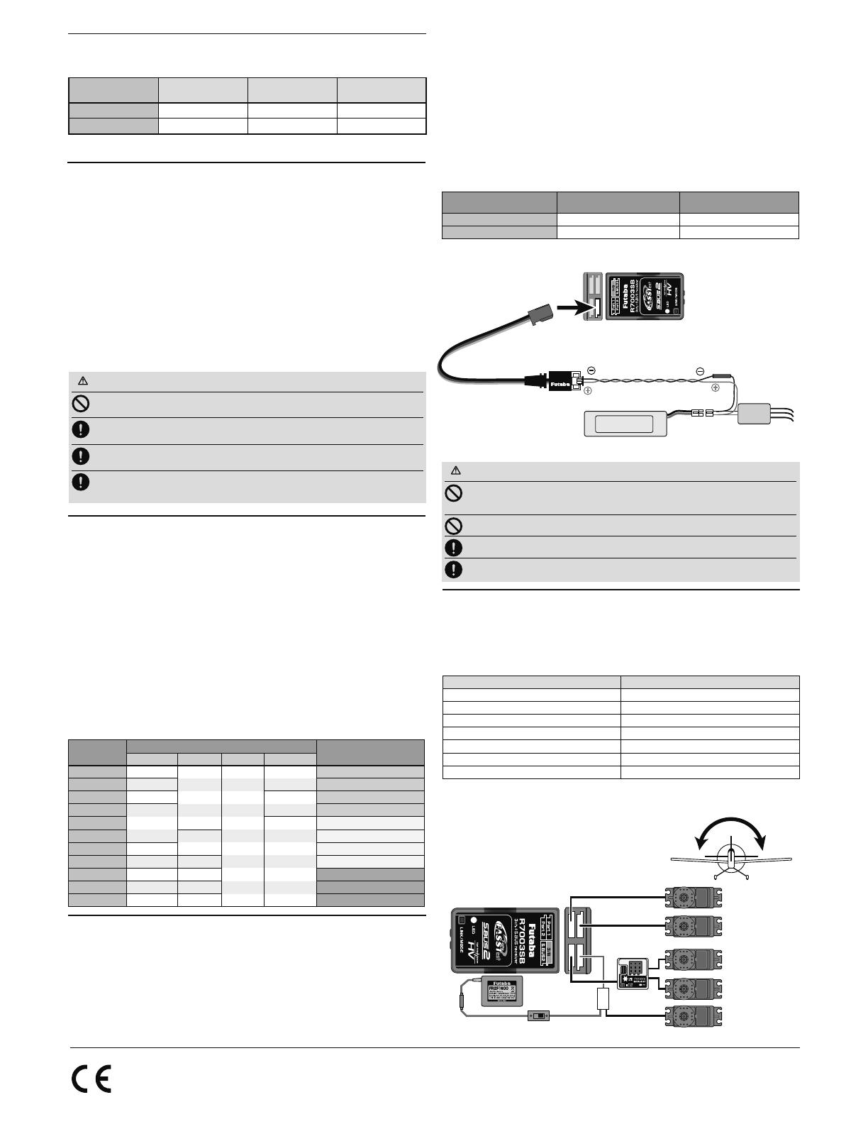
Measurement of Extra Voltag
R7003SB can display the voltage of a receiver battery on a transmitter.
Furthermore, the following procedures are required in order to display the voltage of
another battery (Drive battery etc.).
1
The optional adapter for CA-RVIN-700 is purchased.
2
R7003SB is changed into "EXT-VOL Mode" in the following procedure.
*If "EXT-VOL Mode" is used, the port 2 cannot be used as the servo CH.
3
According to the manual of CA-RVIN-700, battery wiring is branched and it
connects.
4
One side of EXT-VOL CABLE is connected to the port 2 of R7003SB.
Channel Modes
The R7003SB is capable of changing its channel allocations as described in the table
below. Please choose the mode which suited the use in the following procedure from the
11 modes.
1
Press and hold down the Link/Mode button on the R7003SB receiver.
[Transmitter is always OFF]
2
Turn the receiver on while holding down the Link/Mode button. After power up,
the button can be released.
3
The LED should now be blinking red with green.
4
Each press of the Mode/Link button advances the receiver to the next mode.
[Refer to CH Mode table shown below.]
5
When you reach the mode that you wish to operate in, press and hold the
Mode/Link button for more than 2 seconds.
6
When LED blinks in green with red, it is the completion of a mode change.
7
Please cycle the receiver power off and back on again after changing the
Channel Mode.
*5 seconds after the receiver ON, LED shows CH Mode.
S.BUS2
S.BUS2 extends S.BUS and supports bidirectional communication. Sensors are connected
to the S.BUS2 port.
*Only S.BUS2 capable devices may be connected to the S.BUS2 port. Standard S.BUS
servos and gyros should not be connected to the S.BUS2 port.
R7003SB CH Mode table
When using the R7003SB Receiver with the GYA430,
GYA431
The following table corresponds to the gyro's functions. A port can be used effectively.
The servo which a gyro controls is connected to a gyro.
* Please refer to the description of each gyro manual.
Gyro control CH CH Mode
Rudder D,E
Elevator F
Aileron G
Elevator+Rudder H
Aileron+Rudder I
Aileron+Elevator J
Aileron+Elevator+Rudder K
S.BUS Gyro Goup table
ZLWKH[WHUQDOSRZHU
LQSXWPXVWEHOHVVWKDQ9
7R0RWRU&RQWUROOHU
RU6HUYR
%UDQFK
)XVH
%ODFNOLQH
5HGOLQH
0RWRU
&RQWUROOHU
(;792/&$%/(
,WLVDWWDFKHGWR56%
2SWLRQ
(;792/&$%/(
WR3RUW
,WFKDQJHVLQWR(;792/0RGH
56%
WR0RWRU
3RZHU%DWWHU\RU
DQRWKHUSRZHUVXSSO\
IRUVHUYRV
FUTABA CORPORATION
oak kandakajicho 8F 3-4 Kandakajicho, Chiyoda-ku, Tokyo 101-0045, Japan
TEL: +81-3-4316-4820, FAX: +81-3-4316-4823
©FUTABA CORPORATION 2018, 5 (3)
  • Page 1 1
  • Page 2 2

Futaba R7003SB User manual

Type
User manual

Futaba R7003SB is a FASSTest-2.4GHz compatible bi-directional communication system receiver featuring S.BUS2/S.BUS port and is also compatible with conventional systems. It allows telemetry data transmission from optional sensors to the transmitter. With 11 selectable channel modes, it offers flexibility in channel allocation. The receiver supports both PWM and S.BUS output and provides extra voltage capability through an optional EXT-VOL cable and CA-RVIN-700 accessory.

Ask a question and I''ll find the answer in the document

Finding information in a document is now easier with AI