Troy-Bilt 21A-654J66 Owner's manual
- Category
- Mini tillers
- Type
- Owner's manual
This manual is also suitable for

OTRO_ n!_LT"
anual
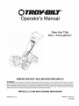
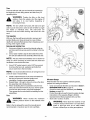
Rear.tine Tiller
4 r T_
65 JmTho oughbred
IMPORTANT:READSAFETYRULESANDINSTRUCTIONSCAREFULLY
WARNING: This unit isequipped with aninternal combustion engine andshould not beusedon or nearany unimproved forest-covered, brush-covered or
grass-covered land unless the engine'sexhaust system is equippedwith aspark arrester meetingapplicable local or state laws (if any). tfaspark arrester is used,it
should be maintained in effective working order by the operator. In the State of California the above is required by law (Section 4442 of the California Public
Resources Code).Otherstates may havesimilar laws, Federallaws applyon federal lands, A spark arrester for the muffler is availablethrough your nearestengine
authorizedservice dealer or contact the service department, P,O,Box 361131 Cleveland,Ohio 44136-0019.
TROY-BILTLLC,P.O.BOX361131CLEVELAND,OHIO44136-0019
PRINTEDIN U.S.A. FORMNO. 769-01146
(3/17/2004)

TABLEOFCONTENTS
Content Page Content Page
Customer Support 2 Maintenance and Adjustments 15
Safety 3 Off-season Storage 21
Assembly 6 Troubleshooting 22
Features and Controls 9 Parts List 23
Operation 11 Warranty Information Back Cover
FINDINGMODELNUMBER
This Operator's Manual is an important part of your new rear-tine tiller. It will help you assemble, prepare and maintain
the unit for best performance. Please read and understand what it says.
@
iliii iii iilli!
www.t roybilt.com _1__ 5u_51180_ _
Before you start assembling your new equipment, please locate the model plate on the equipment and
copy the information from it in the space provided below. A sample model plate is also given below. You can
locate the model plate by standing behind the unit and looking down at rear surface of the tine shield. This
information will be necessary to use the manufacturer's web site and/or help from the Customer Support
Department or an authorized service dealer.
Copy the model number here:
Copy the serial number here:
CUSTOMERSUPPORT
PleasedoNOTreturntheunittotheretailer from whereit waspurchased,withoutfirstcontactingCustomerSupport.
If you have difficulty assembling this product or have any questions regarding the controls, operation or maintenance of
this unit, you can seek help from the experts. Choose from the options below:
_ Visit troy-bgt.com for many useful suggestions. Click on Customer Support button and youwill get the four options reproduced here. Click on the appropriate button and help is
_mmediately available.
7_e 8nswo_ you 8Fe " _e 8plswer you ale
_°_'"*__"°_*"°°'°*"_" _°"__*'"...... looking for could u_j_"-:u""
m_ho_Jf_/_r_IH mFLI_l_d_&, el update ye_lJ U_eJs#ll_l
8 mouse crick 8w8 S
, _o_o, a mouse crick away!
:
If you prefer to reach a Customer Support Representative, please call 1(800) 520-5520.
The engine manufacturer is responsible for all engine-related issues with regards to
and service. Please refer to the
_erformance, power-rating, specifications, warranty engine
manufacturer's Owner's/Operator's Manual, packed separately with your unit, for more
information.

SECTION1: IMPORTANTSAFEOPERATIONPRACTICES
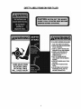
WARNING: This symbol points out important safety instructions which, if not followed, could endanger
the personal safety and/or property of yourself and others. Read and follow all instructions in this manual
before attempting to operate this machine. Failure to comply with these instructions may result in personal
injury. When you see this symbol--heed its warning.
DANGER: This machine was built to be operated according to the rules for safe operation in this man-
ual. As with any type of power equipment, carelessness or error on the part of the operator can result in
serious injury. This machine is capable of amputating hands and feet and throwing objects. Failure to
observe the following safety instructions could result in serious injury or death.
California Proposition 65 Warning:
WARNING: Engine exhaust, some of its constituents, and certain vehicle components contain
or emit chemicals known to the State of California to cause cancer and birth defects or other
reproductive harm.
Training
1. Carefully read this Operator's Manual, the separate
Engine Owner/Operator's Manual, and any other
literature you may receive. Be thoroughly familiar
with the controls and the proper use of the tiller and
its engine. Know how to stop the unit and
disengage the controls quickly.
2. Never allow children to operate the tiller. Never
allow adults to operate the tiller without proper
instruction.
3. Keep the area of operation clear of all persons,
particularly children and pets.
4. Keep in mind that the operator or user is
responsible for accidents or hazards occurring to
other people, their property, and themselves.
Preparation
1. Thoroughly inspect the area where the tiller is to be
used and remove all foreign objects.
2. Be sure all control levers are released before
starting the engine.
3. Do not operate the tiller without wearing adequate
outer garments. Avoid loose garments or jewelry
that could get caught in moving parts.
4. Do not operate the tiller when barefoot or wearing
sandals, sneakers, or light footwear. Wear
protective footwear that will improve footing on
slippery surfaces.
5. Do not till near underground electric cables,
telephone lines, pipes or hoses. If in doubt, contact
your telephone or utility company.
6. Never make adjustments when engine is running
(unless recommended by the Engine
manufacturer).
WARNING: Handle fuel with care; it is highlyflammable
and its vapors are explosive. Take the following precautions:
a. Store fuel in containers specifically designed
for this purpose.
b. The gas cap shall never be removed or fuel
added while the engine is running. Allow the
engine to cool for several minutes before
adding fuel.
c. Keep matches, cigarettes, cigars, pipes,
open flames, and sparks away from the fuel
tank and fuel container.
d. Fill fuel tank outdoors with extreme care.
Never fill fuel tank indoors. Use a funnel or
spout to prevent spillage.
e. Replace all fuel tank and container caps
securely.
f. If fuel is spilled, do not attempt to start the
engine, but move the machine away from the
area of spillage and avoid creating any
source of ignition until fuel vapors have
dissipated.
Operation
1.
Do not put hands or feet near or under rotating
parts.
2. Exercise extreme caution when on or crossing
gravel drives, walks, or roads. Stay alert for hidden
hazards or traffic. Do not carry passengers.
3. After striking a foreign object, stop the engine,
thoroughly inspect the machine for any damage,
and repair the damage before restarting and
operating the machine.
4. Exercise caution to avoid slipping or falling.
5. Ifthe unit should start to vibrate abnormally, stop the
engine and check immediately for the cause. Vibration
is generally a warning of trouble.
6. Stop the engine before unclogging the tines, or
when making any repairs, adjustments or
inspections.
7. Take all possible precautions when leaving the
machine unattended. Stop the engine and move
the Wheel Shift Lever to FORWARD.

8. Beforecleaning,repairing,orinspecting,stopthe
engineandmakecertainallmovingpartshave
stopped.
9. Alwayskeepthetiller'sreartineshielddown.
10.Neverusethetillerunlessproperguards,plates,or
othersafetyprotectivedevicesareinplace.
11.Donotrunengineinanenclosedarea.Engine
exhaustcontainscarbonmonoxidegas,adeadly
poisonthatisodorless,colorless,andtasteless.
12.Keepchildrenandpetsaway.
13.Beawarethatthetillermayunexpectedlybounce
upwardorjumpbackwardifthetinesshouldstrike
extremelyhardpackedsoil,frozenground,or
buriedobstacleslikelargestones,roots,orstumps.
Ifindoubtaboutthetillingconditions,alwaysuse
thefollowingoperatingprecautionstoassistyouin
maintainingcontrolofthetiller:
a. Walkbehindandtoonesideofthetiller,
usingonehandonthehandlebars.Relax
yourarm,butuseasecurehandgrip.
b. Useslowerenginespeeds.
c. Clearthetillingareaofalllargestones,roots
andotherdebris.
d. Avoidusingdownwardpressureon
handlebars.Ifneedbe,useslightupward
pressuretokeepthetinesfromdiggingtoo
deeply.
e. Beforecontactinghardpackedsoilattheend
ofarow,reduceenginespeedandlift
handlebarstoraisetinesoutofthesoil.
f. Inanemergency,stoptinesandwheelsby
releasingtheWheelEngagementHandle.
Donotattempttorestrainthetiller.
15.Donotoverloadthetitler'scapacitybyattemptingto
tilltoodeeplyattoofastarate.
16.Neveroperatethetillerathightransportspeedson
slipperysurfaces.Lookbehindandusecarewhen
backingup.
17.Donotoperatethetilleronaslopethatistoosteep
forsafety.Whenonslopes,slowdownandmake
sureyouhavegoodfooting.Neverpermitthetiller
tofreewheeldownslopes.
18.Neverallowbystandersneartheunit.
19.Onlyuseattachmentsandaccessoriesthatare
approvedbyTroy-BiltLLC.
20.Neveroperatethetillerwithoutgoodvisibilityor
light.
21.Neveroperatethetillerifyouaretired,orunderthe
influenceofalcohol,drugsormedication.
22.Operatorsshallnottamperwiththeengine-
governorsettingsonthemachine;thegovernor
controlsthemaximumsafeoperatingspeedto
protecttheengineandallmovingpartsfrom
damagecausedbyoverspeed.Authorizedservice
shallbesoughtifaproblemexists.
23.Donottouchenginepartswhichmaybehotfrom
operation.Letpartscooldown
24.Pleaseremember:Youcanalwaysstopthetines
andwheelsbyreleasingtheWheelEngagement
Handle.
25.Useextremecautionwhenreversingorpullingthe
machinetowardsyou.
26.Starttheenginecarefullyaccordingtoinstructions
andwithfeetwellawayfromthetines.
27.Neverpickuporcarryamachinewhiletheengine
isrunning.
Maintenanceand Storage
1. Keep the tiller, attachments and accessories in safe
working condition.
2. Check all nuts, bolts, and screws at frequent
intervals for proper tightness to be sure the
equipment is in safe working condition.
3. Never store the tiller with fuel in the fuel tank inside
a building where ignition sources are present such
as hot water and space heaters, furnaces, clothes
dryers, stoves, electric motors, etc.). Allow engine
to cool before storing in any enclosure.
4. To reduce the chances of a fire hazard, keep the
engine free of grass, leaves, or excessive grease.
5. Store gasoline in a coot, well-ventilated area, safely
away from any spark- or flame-producing
equipment. Store gasoline inan approved
container, safely away from the reach of children.
6. Refer to the storage instructions in the
Maintenance section of this Manual and the
separate Engine Owner's Manual for instructions if
the tiller is to be stored for an extended period.
7. If the fuel tank has to be drained, do this outdoors.
,_ WARNING: YOUR RESPONSIBILITY Restrict the use of this power machine to persons who read,
understand and follow the warnings and instructions in this manual and on the machine.

SAFETYLABELSFOUNDONYOURTILLER

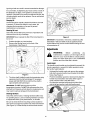
SECTION2: ASSEMBLINGTHETILLER
NOTE: All references to the RIGHT or LEFT side of the
tiller are observed from operator's position.
ToolsNeededforAssembly
9/16" Wrench (Handle Mount Bracket)
7/16" Wrench or Nutdriver (Control Box)
Two 1/2"Wrenches (Threaded Cable Adjuster)
Phillips Screwdriver (Control Box)
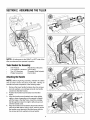
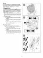
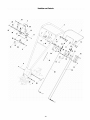
AttachingtheHandle
NOTE: Before beginning assembly, unfasten the cables
and lay them across the back of the tiller. Having an
assistant will ease completion of the following steps.
1. Remove the lower handle hardware (two hex screws,
two lock washers, one carriage screw & one handle
crank) from the titler's frame.
2. Position the handle mount bracket over the tiller
frame.
3. Align the handle mount bracket's rear holes (either
upper or lower, depending on the operator's height)
with the holes in the tiller frame. Insert the carriage
bolt through the holes from right to left and secure it
with the handle crank.
4. Align the handle mount bracket's front holes with the
holes in the tiller frame. Using a 9/16" wrench, secure
the handle mount bracket to the tiller frame with the
hex screws and lock washers removed earlier.

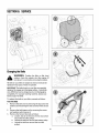
AttachingtheControlBox
5. Remove the four Phillips screws and lock nuts from
the control box plate.
6. Insert the ends of the two springs into the holes found
in the control levers located on the underside of the
handle panel.
7. Using a Phillips screwddver and a 7/16" wrench,
secure the control box to the underside of the handle
panel with the four screws and lock nuts removed
earlier.

XXXXXXXXXXXXXXXXX r¸ J---- --_
/
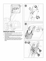
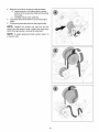
AttachingtheShiftCable
8. Place the shift lever in the forward position. Insert the
end of the shift cable into the hole in shift lever
located on the underside the handle panel.
9. Position the shift cable's threaded adjuster in the slot
found on the shift lever mount bracket. (one nut below
the mount bracket and the flat washer, lock washer
and second nut above the mount bracket. See Inset).
10. Adjust the shift cable as follows:
a. Using a ½" wrench, thread the bottom nut
upward until the cable is taut.
b. Using a ½" wrench, thread the top nut
downward to secure the adjuster to the mount
bracket.
Position the shift cable (and three other cables)
against the left handle tube. Secure them to the
handle with the cable tie provided as shown in the
illustration at the top of the page.
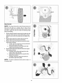
GasandOilFill-up
Gasoline
Service the engine with gasoline as instructed in the
separate Briggs & Stratton Operator/Owner Manual
packed with your tiller. Read instructions carefully.
0il
IMPORTANT:Pour the entire contents of the provided oil
bottle into the engine's oil fill.
f

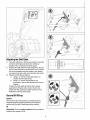
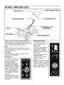
SECTION3: KNOWYOURTILLER
Wheel ShiftLever
Tine DirectionSelector
Wheel EngagementHandle
_Tine EngagementLever
Engine J
Starter Handle
DepthRegulatorLever
(DepthStake)
HandleHeightAdjuster
Read this operator's manual and safety rules before
operating your tiller. Compare the illustrations above with
your unit to familiarize yourself with the location of vadous
controls. Save this manual for future reference.
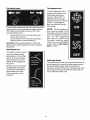
Engine
See the Briggs & Stratton Owner!Operator manual
packed with your unit for the location and function of the
controls on the engine.
Starter Handle
The starter handle is located on the engine. Pull the
starter handle to start engine.
WheelShiftLever
The shift lever is located on the
dght side of the handle panel
and has three positions,
FORWARD, NEUTRAL and
REVERSE. Place the wheel
shift lever in either FORWARD
or REVERSE before engaging
the drive handle. Always bring
the tiller to a complete stop
prior to moving the shift lever
from FORWARD to REVERSE
or vice-versa.
IMPORTANT: Never force the
shift lever. Doing so may result
in serious damage to the tiller's
transmission.
WheelEngagementHandle
The wheel engagement handle
is located below the tilter's
upper handle.
Closing the wheel engagement
handle with the wheel shift
lever in either FORWARD or
REVERSE will cause the tiller's
wheels to drive.
Releasing/Opening the wheel
engagement handle
automatically stops the tiller's
wheels from driving
NOTE: If the tiller's tines and
wheels are engaged, releasing/
opening the wheel engagement
handle automatically stops
BOTH the tiller's tines and the
tiller's wheels from driving.

Tine DirectionSelector
The tine direction selector (found in the lower left area the
handle panel) is used to alternate tine rotation between
FRT mode (Forward Rotating Tines) to CRT mode
(Counter Rotating Tines).
Operate the tiller inCRT mode when tilling virgin
ground, sod or hard soil.
Operate the tiller inFRT mode when cultivating or
tilling soft ground or previously tilled soil.
IMPORTANT: When operating the tiller in FRT mode,
always lower the depth regulator lever (for a shallower
tilling depth).
DepthRegulatorLever
The highest notch (lever all the
way down) raises the tines
approximately 1/2-inch off the
ground. This "travel" position
allows the tiller to be moved
without the tines digging into
the ground.
Moving the lever up increases
the tilling depth. The lowest
notch allows a tilling depth of
approximately six to eight
inches, depending on soil
conditions.
Tine EngagementLever
The tine engagement lever is
located on the left side of the
handle panel and has two
positions, ON and OFF. To
engage the tines and begin
tilling, place the lever in the ON
position. To disengage the
tines, move the lever into the
OFF position.
NOTE: The tlne engagement
lever cannot be placed in the
ON position without first closing
the wheel engagement handle.
Also, the tlne engagement
lever cannot be placed in the
ON position unless the wheel
shift lever is in the FORWARD
position. Refer to SafetyInterlock
Systemon Page 11.
HandleHeightAdjuster
The handle mount bracket can be adjusted downward (for
shorter operators) or upward (for taller operators) using
the handle height adjuster. Align the handle mount
bracket's rear holes with the holes in the tiller frame. Insert
the carriage bolt through the holes from right to left and
secure it with the handle crank.
10

SECTION4: OPERATINGYOURTILLER
WARNING: Read, understand, and follow all
instructions and warnings on the machine, in
this manual and the Briggs & Stratton Owner/
Operator manual packed with your unit before
operating the tiler.
SafetyInterlockSystem
IMPORTANT:Your tiller is equipped with an interlock
system for the protection of the operator. If the interlock
system should ever malfunction, do not operate the tiller.
Contact an authorized service dealer.
The Wheel Engagement Handle must be in the closed
position inorder to engage the tines
The Wheel Shift Lever must be in the FORWARD
position inorder to engage the tines.
The Wheel Shift Lever cannot be moved out of the
FORWARD position unless the Tine Engagement
Lever is in the OFF position.
The tines will automatically stop if the operator
releases the Wheel Engagement Handle.
The wheels will automatically stop ifthe operator
releases the Wheel Engagement Handle.
,_ WARNING: Do not operate the tiller if the
interlock system is malfunctioning. This system
was designed for your safety and protection.
Pre-StartChecklist
Do the following before starting the engine.
1. Check unit for loose or missing hardware. Service as
required.
2. Check motor oil level. Refer to separate Briggs &
Stratton Operator/Owner Manual.
3. Check that all safety guards and covers are in place.
4. Check air cleaner and engine cooling system. Refer
to separate Briggs & Stratton Operator/Owner
Manual.
5. Select a tine direction (Refer to TineDirectionSelector
on page 10).
6. Fill the fuel tank with gasoline as instructed in the
separate Briggs & Stratton Operator/Owner Manual
packed with your tiller. Read instructions carefully.
WARNING: Gasoline is highly flammable and
its vapors are explosive. Follow gasoline safety
rules found on Page 3 in this manual, and in the
separate Briggs & Stratton Operator/Owner
Manual. Failure to follow gasoline safety
instructions can result in serious personal injury
and property damage.
7. Set the tilling depth by moving the depth regulator
lever rearward, then either up or down into the
desired depth setting. Refer to DepthRegulatorLeveron
Page 10.
NOTE: Move the Depth Regulator Lever into the "travel"
position (lever all the way down) so that the tines clear the
ground. Use this position when practicing with or
transporting the tiller. When you are ready to begin tilling,
move the Depth Regulator Lever into the desired depth
setting. Refer to DepthRegulatorLeveron Page 10.
StartingEngine
Move choke control lever to CHOKE position.
NOTE: A warm engine may not require choking.
Move throttle control lever to FAST (rabbit) position.
(
Grasp the starter handle and pull the rope out slowly
until resistance is felt. When itbecomes slightly
harder to pull the rope, slowly allow the rope to recoil.
Then pull rope with a rapid, continuous, full arm
stroke. Keep a firm grip on starter handle.
Maintain a grip on the starter handle and allow the
rope to recoil slowly.
Repeat the previous steps until engine starts. When
engine starts, move choke control gradually toward
the RUN position until the engine is running smoothly.
,_ WARNING: Never run the engine indoors or
in a poorly ventilated area. Engine exhaust
contains carbon monoxide, an odorless and
deadly gas.
11

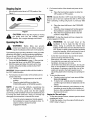
StoppingEngine
Move throttle control lever to STOP position. See
Figure 1.
Figure 1
CAUTION: Never stop the engine by moving
the choke lever into the CHOKE position.
Backfire, fire or engine damage could result.
OperatingtheTiller
WARNING: Before tilling new ground,
contact your telephone and utilities company to
inquire if underground lines are on the property.
The following pages provide guidelines to using your tiller
effectively and safely in various gardening applications.
Be sure to read Tilling Tips & Techniques in this Section
before you actually put the tines into the soil.
1. Follow the Pre-StartCheckliston page 11. Be sure that
the wheel shift lever is in the NEUTRAL position.
2. Start the engine and allow itto warm up for a few
minutes. Move the throttle control into the FAST
speed setting.
IMPORTANT: Always operate the tiller with the throttle in
the FAST (rabbit) position.
3. For forward or reverse motion of the wheels and no
power to the tines:
a. Place the tine engagement lever in the OFF
position.
b. Place the wheel shift lever in either the
FORWARD position or REVERSE position.
NOTE: If you encounter difficulty repositioning the
wheel shift lever from FORWARD or REVERSE into
NEUTRAL or vice-versa, gently rock the tiller (slightly
push-and-pull the handlebar forward and backward) prior
to moving the wheel shift lever. Doing so will help fully
disengage the transmission's internal drive clutch.
c. Close the wheel engagement handle against
the handlebar to cause the wheels to drive. To
stop the wheels, release the wheel
engagement handle.
4. For forward motion of the wheels and power to the
tines:
a. Place the tine direction selector in either the
CRT position or FRT position.
NOTE: Operate the tlller in CRT mode when tilling virgin
ground, sod or hard soil. Operate the tiller in FRT mode
when cultivating or tilling soft ground or previously tilled
soil.
b. Place the wheel shift lever in the FORWARD
position.
c. Close the wheel engagement handle against
the handlebar to cause the wheels to drive.
d. Place the tine engagement lever in the ON
position to begin tilling.
IMPORTANT: To stop the wheels and tines, release the
wheel engagement handle.
WARNING: Do not push down on the
handlebar to try to make the tiller till more
deeply. Doing so prevents the wheels from
holding the tiller back and can allow the tines (in
CRT mode) to rapidly propel the tiller backward
toward the operator, which could result in loss of
control, property damage, or personal injury.
As the tiller moves forward, relax and letthe wheels
pull the unit along while the tines dig.
Walk behind, and a littleto one side of the tiller.
Use a light but secure grip with one hand on the
handlebars, but keep your arm loose.
Let the tiller move ahead at itsown pace. Do not push
down on the handlebar inan attempt to force the tiller
to dig deeper. If necessary, stop the tiller, turn off the
engine and reposition the depth regulator lever to
adjust tilling depth before restarting and operating the
tiller.
5. To turn the tiller around:
a. Practice turning in a level, open area with the
tines not engaged.
b. To start a turn, carefully raise the handlebar
until the engine and tines are balanced over the
wheels.
c. With the tiller balanced, push sideways on the
handlebar to move the tiller in the direction of
the turn. After completing the turn, slowly lower
the tines into the soil.
StoppingtheTiller andEngine
1. To stop the wheels and tines, release/open the wheet
engagement handle.
2. To stop the engine, move the engine throttle lever to
STOP. Refer to Figure 1.
12

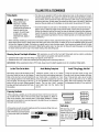
TILLINGTIPS& TECHNIQUES
Tilling Depths • Thistiller canbeoperatedin CRT(counter-rotatingtine) mode.Asthe wheelspullforward,
thetines rotatebackward•Thiscreatesan"uppercut"tineactionwhichdigsdeeply,uprooting
_"L, WARNING: Before soilandweeds.Don'toverloadtheenginewhenoperatingin CRTmode,butdigasdeeplyas
,_lk tilling' €°ntact y°ur possibleon eachpass.0n laterpasses,thewheelsmaytendto spininthesoftdirt. Helpthem
alongby lifting up slightlyon thehandlebar(orsimply switchto operatingin FRTmode)•
,_, B te ephoneor ut t es
companyandinquire if
underground equipment or
linesareusedonyour
property. Donottill near
buried electriccables,
telephonelines, pipesor
hoses.
• Avoidthetemptationto pushdownonthehandlebarin anattemptto forcethetiller to dig
deeper.Doingsotakestheweight offthe poweredwheels,causingthemto losetraction.
Withoutthewheelsto holdthetiller back,thetineswill attemptto propelthetiller backward,
towardstheoperator•(Sometimes,slightdownwardpressureonthe handlebarwill helpget
through aparticularlytoughsectionofsodor unbrokenground,butinmostcasesthis won't
benecessary.)
• Whencultivating(breakingupsurfacesoilaroundplantsto destroyweeds),adjustthetinesto dig onlyl'_to 2"deep.Usingshallowtilling
depthshelpspreventinjuryto plantswhoseroots oftengrow closeto thesurface•If needed,lift up onthe handlebarslightlyto prevent
thetinesfrom diggingtoo deeply•(Cultivatingona regularbasisnotonlyeliminatesweeds,italsoloosensandaeratesthesoil for better
moistureabsorptionand fasterplantgrowth.)Wateringthegardenareaa few daysprior totilling will maketilling easier,aswill letting
the newlyworkedsoil setfor a dayor two beforemakinga final,deeptilling pass.
ChoosingCorrectTine Depth&RotationWith experience,youwill findthe "justright" tilling dePth addfine rotation combination
thatisbestfor yourgardenunderspecificconditions.
• Operatethetiller inCRTmodewhentillingvirgin ground,sodor hardsoil.
• 0peratethetiller inFRTmodewhencultivatingortilling softgroundor previouslytilled soil.
IMPORTANT:Whenoperatingthe tiller in FRTmode,alwayslowerthe depth regulatorlever(for ashallower tilling depth).
Letthe Tiller Dothe Work
Whiletilling, relaxand letthewheelspullthe
tiller along while the tines dothe digging.
Walkon thesidethat is notyetfinished (to
avoidmakingfootprints in thefreshlytilled
soil) and lightly,but securelygrip the han-
dlebarwith just onehand.Always operate
thetiller withthe throttle inthe FAST(rab-
bit) position.
AvoidMakingFootprints
Whenever possible,walk on the untilled
sideof theunitto avoidmakingfootprints in
your freshly tilled or cultivated soil. Foot-
prints causesoil compactionthat can ham-
per root penetrationand contributeto soil
erosion. They canalso '!plant" unwanted
weed seeds back into the freshly tilled
ground.
AvoidTilling Soggy,WetSoil
Tillingwet soil often resultsin large,hard
clumpsof soilthat can interferewith plant-
ing. If time permits,wait a dayor twoafter
heavyrainsto allow the soil to dry before
tilling. Testsoil bysqueezingit intoa ball.If
it compressestoo easily,it istoo wettotill.
PreparingSeedbeds
•Whenpreparinga seedbed,gooverthesamepathtwiceinthefirst row,thenover-
lapone-halfthetiller width on the rest of the passes(seeSeedbed1). Whenfin-
ishedinone direction,makea secondpassata right angle(Seedbed2). Overlap
eachpassfor bestresults(in veryhardground,it maytakethreeorfour passesto
thoroughly pulverizethesoil.) Seedbed1
Cultivating
Seedbed2
• Ifthegardensizewill notpermitlengthwiseandthencrosswisetilling, thenover- ,.,.....
• _ w_rnp_annmg,youcan •r "r
laptheflrstpassesbyone halfatiller *._ _ ._
width,followedbysuccessivepasses _tWeee_°rUogwhsrt°°cmt vate _- _ _ _
atone- uarterwdth seeSeedbed " -"_- _ "_"
3' q ( ........................... Leaveroom for the hood _ _.
width, plus enough extra _ _
• _"" ' roomforfutureplant m "4_" _iL'
Seedbed3 growth. _ ---r
13

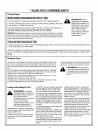
TILLINGTIPS& TECHNIQUES(CON'T)
Tilling OnSlopes
Readthefollowingrecommendationsbeforetilling on slopes:
A%
youmustgardenon a moderateslope,pleasefollow two very importantguidelines:
If
H
1.Tillonlyonmoeerateslopes,neveron steepgroundwherefooting s difficult reviewsafe-
[y rulesinSection1: Safet/of this manual).
2. We recommendtilling up and clownslopes ratherthan terracing.Tilling verticallyon a
slopeallows maximumplantingareaandalsoleavesroomfor cultivating.
IMPORTANT:WhenrHHngon slopes,besurethe correctoil levelismaintainedintheengine
(checkeveryone-halfhourofoperationLTheinclineoftheslopewillcausetheoil togravitate
WARNING: Donot
operatetiller on a slopetoo
steepfor safeoperation. Till
slowly and be sureyou have
good footing. Neverpermit
tiller to freewheeldown
slopes. Failureto follow this
warning could result in
personalinjury.
awayfrom its normallevelandtn_scanstarveenginepartsofrequiredlubrication.Keepthe
motoroil levelattheful pointatall t_mes!
Tilling Upand DownSlopes{VerticalTilling)
• Tokeepsoilerosionto a minimum,besureto addenougnorganicmatterto theSOl{sothatit hasgoonmoisture-holdingtextureandtry
Eoavoidleavingfootprints or wheelmarks.
•Whentilling vertically,try tomakethefirst _assuphillasthetillerdigsmoreeeeplygong uphillthanitdoesdownhill. Insoftsoil orweeds.
you mayhaveto lift thehandlebarsslightlywhile goinguphill.Whengoing downhill,overlapthefirst passbyaboutone-halfthewidth of
thetiller.
ClearingtheTines
Thetines havea self-clearingactionwhicheliminatesmosttanglingof debrisin the
tines.However,occasionallydrygrass,stringystalksortoughvinesmaybecometan-
gled.Followtheseprocedurestohelpavoidtanglingandto cleanthetines,if neces-
sary.
Toreducetangling,setthedepthregulatordeepenoughto getmaximum chopping
actionasthetineschopthematerialagainsttheground.Ais0,trYtotill undercrop
residuesor covercropswhiletheyaregreen,moistandtender.
• Whiletilling, try swayingthe handlebarsfrom sideto side(about6"to !2"). This
"fishtail!rig"actionoftenclearsthet{nesofdebris.
• Iftanglingoccurs,lift thetinesoutofthesoilandrunthetiller in reversefor a few
feet.Thisreversingact{onshouldunwindagooddealofdebris.
• Itmaybenecessaryto removethedebrisbyhand(a
pocketknifewill he!pyouto cutawaythematerial).
,_ WARNING: Beforeclearingthe
tinesbyhand,stoptheengine,allowall
movingpartstostop.Failuretofollow
thiswarningcouldresultin personal
injury,
Loading and Unloadingthe Tiller ' Usesturdyrampsandmanually(engineshut • Whengoingdownramps,walkbackward
off) rollthetillerintoandoutofthevehicle, withthetillerfollowingyou.Keepalertfor any
_hb WARNING: Loadingand Twoor morepeopleareneededtodothis. obstaclesbehindyou.Positionapersonat
unloadingthetillerint0avehicleis •TTherampsmustbestrongenoughtosupport eachwheelto controlthespeedofthetiller.
potentiallyhazardous.Doingsois thecombinedweightofthetillerandanyban- Never godownrampstiller-firstlasthetiller
NOTrecommendunless dlers.Therampsshouldprovidegoodtraction couldtipforward.
absolutelynecessary,asthiscould to preventslipping;theyshouldhavesiderails •Placewoodenblocksonthedownhillsideof
resu{tin personalinjuryor to guidethetilleralongtheramps;andthey thewheelsifyouneedtostopthetil!erfrom
propertydamage.However,ifyou shouldhavealockingdevicetosecurethemto rollingdowntheramp.Also,usetheblocksto
mustloador unloadthetiler, thevehicle, temporarilykeepthetiller inplaceonthe
followtheguidelinesgivennext. • Thehandlersshouldwearsturdyfootwearthat ramps(ifnecessary),andto chockthewheels
•Beforeioadingorunloading,St0ptheengine, willhelptopreventSflpping. in placeafterthetiler isinthevehicle.
wa{tforallpartstostopmovingandallowthe • Positiontheloadingvehiclesothattheramp °Afterloadingthetiller,preventitfrom rolling
engineandmufflercool. angleisasflataspossible(thelessinclineto byplacingthewheelshiftleverintheFOR-
. Thetilleristooheavvandbulkyto liftSafely the ramp,thebetter).Turnthevehicle'sengine WARDposition.Chockthewheelswith blocks
byoneperson.Twoormorepeopleshould_ offandapplyits parkingbrake, andsecurelytietheti!lerdown.
sharetheload. • Whengoingupramps,standinthenormal
operating positionandpushthetilleraheadof
you.Haveapersonateachsideto turnthe
wheels.
14

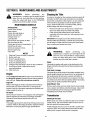
SECTION5: MAINTENANCEANDADJUSTMENTS
WARNING: Before performing any
maintenance, or repairs, turn the engine off and
allow it to cool, move the tiller to a level surface,
place the wheel shift lever in the FORWARD
position and chock the tilter's wheels.
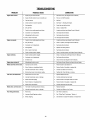
MAINTENANCESCHEDULE
PROCEDURE NOTES
Check motor oil level 2, 3
Clean engine 2, 7
Check drive belt tension 1,4
Check nuts and bolts 1,4
Change motor oil 1,4, 6
Lubricate tiller 4, 8
Service foam pre-cleaner air filter 7
Service paper air filter 7
Check gear oil level in transmission 1, 5
Check tines for wear 5
Check air pressure in tires 5
Service spark plug 7
Clean tiller 8
NOTES
1. After first 2 hours of break-in operation.
2. Before each use.
3. Every5 operating hours.
4. Every 10 operating hours.
5. Every 30 operating hours.
6. Change more frequently in dusty or dirty conditions.
7. See Engine Owner's Manual for service
recommendations.
8. After each use.
Engine
Check engine oil level before each use as instructed in
the Briggs & Stratton Operator/Owner Manual packed
with your unit. Follow the instructions carefully.
EngineOil
Refer to the Briggs & Stratton Operator!Owner Manual
packed with your unit for instruction on changing the
engine oil and for information regarding the quantity and
proper weight of motor oil.
AirCleaner
Service the pre-cleaner, if so equipped, and cartridge/air
cleaner element as instructed in the Briggs & Stratton
Operator/Owner Manual packed with your unit.
Spark Plugs
The spark plug should be cleaned and the gap reset once
a season. Refer to the Briggs & Stratton Operator/Owner
Manual for correct plug type and gap specifications.
CleaningtheTiller
Any fuel or oil spilled on the machine should be wiped off
promptly. Do NOT allow mud and debris to accumulate
around the cooling fins of the engine or on any other part
of the machine, especially around the bottom frame
cover, under the belt cover, around the belts, pulleys,
shifter linkage and other moving parts.
Remove the belt cover at least once a season and
clean any debris away from belts and pulleys
Clean around the bottom frame cover and the
underside ofthe tine shield and with a garden hose
after each use.
IMPORTANT:Thoroughly dry the tine shield and entire
machine after each cleaning. Lubricate any pivot points
and all axles to inhibit rust from forming and metal parts
from corroding and seizing over time.
Lubrication
Engine
WARNING: Before performing any
maintenance or repairs, turn the engine off and
allow it to cool, move the tiller to a level surface,
place the wheel shift lever in the FORWARD
position and chock the titler's wheels.
Lubricate the engine with motor oil as instructed in the
Briggs & Stratton Operator/Owner Manual packed with
your unit.
PivotPoints& Linkage
Lubricate all the pivot points on the depth regulator lever,
handle height adjuster and levers (found on underside of
the handle panel) at least once a season with light oil.
Remove the belt cover at least once a season and clean
any debris away from belts and pulleys before lubricating
pivot points on pulley brackets with a light oil.
Axles(Wheel &Tine)
Remove each wheel and tine holder from its axle at least
once a season and before extended storage. Clean each
axle and lubricate with an all-purpose grease before
reinstalling each wheel and tine holder.
Transmission
Checkingfor 0il Leaks
Before each use, check your tiller for signs of an oil leak--
usually a dirty, oily accumulation either on the unit or on
the floor where it has been parked.
A little seepage around a cover or oil seal is usually not a
cause for alarm. If a small puddle forms below the tiller
within hours, however, then service is required.
15

Ignoring a leak can result in severe transmission damage.
If a cover leaks, try tightening any loose screws or bolts. If
the fasteners are tight, a new gasket or oil seal may be
required. If the leak is from around a shaft and oil seal, the
oil seal probably needs to be replaced. See an authorized
service dealer.
ChangingOil
Oil level should be visually checked if evidence of a leak
is present. Oil should be added in such cases, but
changing the transmission oil as part of general
maintenance is unnecessary
CheckingOil Level
Check the oil level after every 30 hours of operation and
whenever there is any oil leakage.
IMPORTANT:Never operate the tiller if the transmission is
low on oil.
1. Position the tiller on a level surface.
2. Remove the fill plug found on the front of the
transmission. See Figure 2.
J
Figure 2
3. The drive shaft (visible through the transmission plug
opening) should be half-submerged. If necessary,
slowly add SAE 85W140 oil until the drive shaft is
approximately half-submerged.
IMPORTANT: Do NOT add oil to the top of the
transmission housing. Do NOT fully submerge the drive
shaft with oil. Doing so will not allow for oil expansion and
may result in serious damage to the transmission.
CheckingHardware
Check the unit for loose or missing hardware after every
10 operating hours. Loose or missing hardware can lead
to equipment failure, poor performance, or oil leaks.
Be sure to check the three mounting screws located on
each of two end caps found at the rear of the transmission
(See Figure 3). Lift the tine flap to service those screws.
Figure 3
IMPORTANT: If loosened or removed, a sealant (Loctite
Ultra Black TM Silicone 5900) must be applied tothese
screws before they can be reused without risking the loss
of transmission oil.
Adjustments
WARNING: Before performing any
maintenance or repairs, turn the engine off and
allow it to cool, move the tiller to a level surface,
place the wheel shift lever in the FORWARD
position and chock the titler's wheels.
HandleHeight
The handle mount bracket can be adjusted downward (for
shorter operators) or upward (fortaller operators) using
the handle height adjuster.
Unthread the handle crank and remove the carriage
bolt which secures handle mount bracket to the tiller
frame. See Figure 4.
Pivot the handlebar upward or downward to align the
handle mount bracket's rear holes (either upper or
lower) withthe holes in the tiller frame.
Re-insert the carriage bolt through the holes from
right to left and secure itwith the handle crank.
Figure 4
16

ShiftCable
If the tiller's wheels do not "freewheel" when the wheel
shift lever is inthe NEUTRAL position, the shift cable is in
need of adjustment. Refer to Step 10 on Page 8 for
detailed instructions.
Tine EngagementCables
If the tines fail to drive when the tine engagement lever is
placed in the ON position, or if the tines fail to stop when
the tine engagement lever is placed in the OFF position,
DO NOT OPERATE THE TILLER. The tine engagement
c able is in need of adjustment.
1. Remove the belt cover by removing the top screw and
washer (and loosening the side screws) which secure
it.
2. To adjust the cable:
a. Loosen the inside hex nut found on the cable
adjuster.
b. Loosen the outside hex nut found on the cable
adjuster.
c. Grasp the metal cable housing and gently pull
outward to take up slack (usually no more than
1/4-inch) in the cable before retightening both
hex nuts loosened earlier.
Wheel EngagementCable
1. Adjust the wheel engagement cable as follows:
a. Using a ½" wrench, loosen the upper hex nut
found on the cable adjuster.
b. Loosen the lower hex nut found on the cable
adjuster.
c. Grasp the metal cable housing and gently pull
outward to take up slack (usually no more than
1/4-inch) in the cable before retightening both
hex nuts loosened earlier.
17

SECTION6: SERVICE
)
ChangingtheBelts
WARNING: Position the tiller on flat, level
surface, chock the wheels, shut the engine off
and allow it to cool before removing the belt(s).
All belts on your tiller are subject to wear and should be
replaced if any signs of wear are present.
IMPORTANT:The belts found on your tiller are specially
designed to engage and disengage safely. A substitute
(non-OEM) belt can be dangerous by not disengaging
completely. For a proper working machine, always use
factory approved belts.
To replace the belts on your tiller, proceed as follows:
Tine DriveBelts
1. Remove the belt cover by removing the top screw and
washer (and loosening the side screws) which secure
it.
2. Remove the belt keeper rod by removing the screw
and washers which secure it.
3. Remove the forward tine belt as follows:
a. Loosen, but do not remove, the hex nuts which
secure the two idler pulleys.
b. Unloop the belt from around the bottom pulley.
c. Unloop the belt from around the two idler
pulleys.
18

4. Begintheremovalthereversetinebeltasfollows:
a. Applypressureontheidlerpulleystorelieve
tensiononthereversetinecableandthewheel
drivecable.
b. Carefullyunhookeachcable-end.
5. Unloopthewheeldrivebeltfromaroundtheengine
pulley.
6. Unloopthereversetinebeltfromtheenginepulley.
NOTE: Replace the reverse tine belt first and the
forward tine belt second. Lastly, reattach the wheel drive
belt to the engine pulley or proceed by replacing it.
NOTE: To install replacement belts, perform steps 1-6
in reverse order.
19

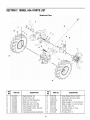
WheelDriveBelt
NOTE: The wheel drive belt is under the least amount of
load and will wear at a slower rate. It may not be
necessary to replace the wheel drive belt as often as the
tine belts. Inspect the belt and read the following steps
before proceeding.
1. Remove the left wheel by removing the cotter pin and
clevis pin which secure it. Use a jack stand or wood
blocks to secure the left wheel axle and stabilize the
tiller.
2. Remove the upper two screws which secure the
bottom frame cover and pivot it downward.
3. Remove the wheel drive belt from around the lower
idler pulley as follows:
a. Loosen, but do not remove, the hex bolt which
secures the lower idler pulley.
b. Unloop the belt from around the lower idler
pulley and transmission pulley.
4. Remove the wheel drive belt from around the upper
idler pulley as follows:
a. Carefully remove the small spring from the
upper pulley's idler bracket.
b. Gently pry the belt keeper tab upward with a
flathead screwdriver.
c. Carefully unloop the wheel drive belt from
around the upper idler pulley.
NOTE: To install a replacement belt, perform steps 1-4
in reverse order.
,I
o
Q,}
ol
\
\
2O
Page is loading ...
Page is loading ...
Page is loading ...
Page is loading ...
Page is loading ...
Page is loading ...
Page is loading ...
Page is loading ...
Page is loading ...
Page is loading ...
Page is loading ...
Page is loading ...
-
 1
1
-
 2
2
-
 3
3
-
 4
4
-
 5
5
-
 6
6
-
 7
7
-
 8
8
-
 9
9
-
 10
10
-
 11
11
-
 12
12
-
 13
13
-
 14
14
-
 15
15
-
 16
16
-
 17
17
-
 18
18
-
 19
19
-
 20
20
-
 21
21
-
 22
22
-
 23
23
-
 24
24
-
 25
25
-
 26
26
-
 27
27
-
 28
28
-
 29
29
-
 30
30
-
 31
31
-
 32
32


Troy-Bilt 21A-654J66 Owner's manual
- Category
- Mini tillers
- Type
- Owner's manual
- This manual is also suitable for
Ask a question and I''ll find the answer in the document
Finding information in a document is now easier with AI
Related papers
-
Troy-Bilt 654J User manual
-
Troy-Bilt 21D-64M1066 Owner's manual
-
-
-
-
Troy-Bilt 644HMBRONCO User manual
-
-
-
-
Other documents
-
ACE 21C-65M1066 Owner's manual
-
-
MTD 214-412-000 User manual
-
Dirty Hand Tools 100983 User manual
-
Powermate PRTT196E User manual
-
Snapper 8.5 TP User manual
-
MTD 342 Series Owner's manual
-
Southland SRTT196E User guide
-
-