Page is loading ...

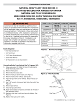
LP & HIGH ALTITUDE LP CONVERSION KIT
FOR INSTALLATIONS IN THE UNITED STATES (0 -10,000 FT)
IMPORTANT: Please read all instructions before converting
the furnace. Pay attention to all safety warnings and any other
special notes highlighted in the manual. Safety markings are
used frequently throughout this manual to designate a degree
or level of seriousness and should not be ignored. WARNING
indicates a potentially hazardous situation that if not avoided,
could result in personal injury or death. CAUTION indicates a
potentially hazardous situation that if not avoided, may result in
minor or moderate injury or property damage
This conversion kit is only to be used to convert a natural gas
unit to LP/Propane gas or to an LP high altitude application in
the United States. This kit may only be used in units installed in
altitudes between zero and 10,000 feet above sea level.
Kits have detailed listings of orifices required for converting light
commercial units to LP Gas for altitudes between 0 & 10,000
feet. Please check kit needed for your application. Verify the
contents of the conversion kit with that of the parts listing, and
familiarize yourself with each component.
INSTALLATION INSTRUCTIONS
FOR R7TQ LIGHT COMMERCIAL PACKAGE GAS / ELECTRIC UNITS
The installer performing this work assumes all responsibility for this
conversion. These instructions are primarily intended to assist qualified
individuals experienced in the proper installation of these components.
Some local codes require licensed installation/service personnel for this
type of equipment. Safety should always be the deciding factor when
installing this product and using common sense plays an important role
as well. Improper installation of the components or failure to follow safety
warnings could result in serious injury, death, or property damage. After
completing the installation, return these instructions to the homeowner’s
package for owner-user’s future reference.
RISQUE D’INCENDIE OU D’ EXPLOSION
•Le non-respect des avertissements de sécurité
pourraitentraînerdesblessuresgraves,lamort ou
desdommagesmatériels.
•L’installationetl’entretiendoiventêtreeffectuéspar
uninstallateurqualié,unorganismedeserviceoule
fournisseur de gazstaller, service agency or the gas
supplier.
•Nepasentreposerniutiliserdel’essencenid’autres
vapeursouliquidesinammablesdanslevoisinage
decetappareil,nidetoutautreappareil.
QUE FAIRE S’IL Y A UNE ODEUR DE GAZ
•Nepastenterd’allumeraucunappareil.
•Netoucheràaucuninterrupteurélectrique;n’utiliser
aucuntéléphonedanslebâtiment.
•Évacuerl’immeubleimmédiatement.
•Appeler immédiatement le fournisseur de gaz en
employant le téléphone d’un voisin. Respecter à la
lettre les instructions du fournisseur de gaz.
•Sipersonnenerépond,appelerleservicedesincendies.
AVERTISSEMENT
DO NOT DESTROY THIS MANUAL. KEEP IN A
SAFE PLACE FOR FUTURE REFERENCE.
FIRE OR EXPLOSION HAZARD
•Failuretofollowsafetywarningsexactlycouldresult
inseriousinjuryorpropertydamage.
•Installationandservicemustbeperformedbyaqualied
installer,serviceagencyorthegassupplier.
•Donotstoreorusegasolineorotherammablevapors
andliquidsinthevicinityofthisoranyotherappliance.
WHAT TO DO IF YOU SMELL GAS
•Donottrytolightanyappliance.
•Donottouchanyelectricalswitch;donotuseanyphone
in your building.
•Leavethebuildingimmediately.
•Immediatelycallyourgassupplierfromaneighbor’s
phone.Followthegassupplier’sinstructions.
•If you cannot reach your gas supplier, call the re
department.
WARNING:
LP Conversion Kit - 1011435 - 100k BTU to 8k ft.,
225k BTU to 4k ft.
DescriptionofComponent UOM Qty P/N
GAS ORIFICE #46 EA 2 273353
GAS ORIFICE #47 EA 2 273354
GAS ORIFICE #48 EA 5 273355
GAS ORIFICE #49 EA 5 273356
GAS VALVE CONVERSION SPRING KIT
FOR 100 /166 BTU
EA 1 624667
GAS VALVE CONVERSION SPRING KIT
FOR 200 / 225 BTU
EA 1 197207
PRESSURE SW .75 EA 1 203933
LABEL,LP&HI ALT. CONV.,WARNING EA 1 703935
LABEL, LP/HI ALT. CONV.INFO, LC EA 1 1011987
LP Conversion Kit - 1011436 - 100k BTU 9k to 10k ft.,
166k / 2000k BTU 2k to 10k ft., 225k BTU 5k to 10k ft.
DescriptionofComponent UOM Qty P/N
GAS ORIFICE, #50 EA 5 273357
GAS ORIFICE, #51 EA 5 273358
GAS ORIFICE, #52 EA 5 273359
GAS VALVE CONVERSION SPRING KIT
FOR 100 /166 BTU
EA 1 624667
GAS VALVE CONVERSION SPRING KIT
FOR 200 / 225 BTU
EA 1 197207
PRESSURE SW .75 EA 1 203933
LABEL,LP&HI ALT. CONV.,WARNING EA 1 703935
LABEL, LP/HI ALT. CONV.INFO, LC EA 1 1011987
PRESSURE SW 1.00” BROWN LABEL EA 1 201160

2
WARNING:
All gas piping must conform with local building
codes,orintheabsenceoflocalcodes,withthe
mostrecenteditionofCGAB149.1.DONOTattempt
tomodify,ortapintoexistinggaslinesyourself.Fire
orexplosionmayresultcausingpropertydamage,
personalinjuryorlossoflife.Failuretofollowthe
safetywarningsexactlycouldresultinseriousinjury,
deathorpropertydamage.
WARNING:
All electrical wiring must comply with the latest
edition of the Canadian Electrical Code (CSA
C22.1and/orlocalcodes).Failuretofollowthese
instructions could result in possible damage to
equipment,seriouspersonalinjury,ordeath.
REMOVING THE BURNER MANIFOLD
1. STOP! Read all the steps in the “Before you Convert the Unit”
section above.
2. Remove 1 screw to allow heat surface cover to slide out
3. Remove the (Blue) wire from the Low Stage terminal of the
gas valve. Remove the (Violet) wire from the High Stage
terminal of the gas valve. Remove (Brown) common wire from
gas valve.
4. Remove (if installed) supply gas piping from the gas valve.
5. Remove 4 fasteners that secure the gas manifold to the burner
box. Carefully remove the gas manifold assembly from the
burner box.
NOTE: The gas manifold assembly consists of the gas valve,
the gas manifold, and the orifices.
6. Identify the gas valve manufacturer listed on the gas valve
label. Convert the valve for operation with LP gas as described
in the appropriate manufacturers instructions.
CONVERTING TO LP / PROPANE GAS
(AT ALTITUDES BETWEEN ZERO & 10,000 FT.)
1. Examine the rating plate of the unit to determine model number
and rated input (Btu/hr).
2. Count the number of burners in the burner box. Verify all
information in the kit to determine the appropriate LP gas
orifice size for your application.
3. Install the appropriate LP gas burner orifices into the gas
manifold.
WARNING:
Do not use Teon tape or pipe joint compound
ontheoricethreads.Theholeintheoricemay
becomeblockedandcausere,explosion,property
damage, carbon monoxide poisoning, personal
injury, or death.
IMPORTANT NOTES:
• Beforeinstallingan orice,checkthefaceor side of
theoriceforthedrillnumbertoensurethatitisthe
appropriatesize.
• Topreventcross threading,hand tighten the orices
intothegasmanifoldassemblyuntilsnug,thentighten
withawrench1/2to1turn.
• Forunitsconvertedforoperationabove2,000ft.,follow
the High altitude deration instructions.
4. Reinstall the gas manifold assembly to the burner assembly
with the 4 screws, that were removed earlier. NOTE: It is
important that the center of the orifices are aligned with the
center of the burners.
5. Reconnect the gas piping to the gas valve inlet.
6. Reconnect the wires to the gas valve terminals.
BEFORE YOU CONVERT THE UNIT
WARNING:
Shutoffthegassupplyatthemanualgasshutoff
valve, before disconnecting the electrical power.
A re or explosion may result causing property
damage,personalinjuryorlossoflife.Failureto
followthesafetywarningsexactlycouldresultin
seriousinjury,deathorpropertydamage.
WARNING:
Toavoidelectricshock,personalinjury,ordeath,
turnofftheelectricpoweratthedisconnectorthe
main service panel before making any electrical
connections.
1. Set the thermostat to the OFF position, or its lowest temperature
setting.
2. Shut OFF the gas supply at the manual shutoff valve located
outside of the appliance.
3. Turn off all electrical power to the appliance.
4. Remove the louvered burner access panel.
5. Move the gas valve ON/OFF knob to the OFF position. See
Figure 2 (page 6)

3
Figure1.TypicalBurnerBoxforLightCommercial
Units
HIGH ALTITUDE DERATION
High altitude application with this unit depends on the installation
altitude and the heating value of the gas. At high altitudes, the
heating value of natural gas is always lower than the heating
value at sea level.
All installations of this equipment must be made in accordance
with the National Fuel Gas Code or with local jurisdiction codes.
For installations at altitudes 2,000 feet or below, the installer does
not need to derate the heat exchanger performance.
WARNING:
The reductionof input rating necessary for high
altitudeinstallationmayonlybeaccomplishedwith
factorysuppliedorices.Donotattempttodrillout
oricesintheeld.Improperlydrilledoricesmay
causere,explosion,carbonmonoxidepoisoning,
personalinjuryordeath.
IMPORTANT NOTES:
• Foranyinstallationthatexceeds2,000feet,theinput
rate must be reduced 4% per 1,000 feet of altitude
(Example: 12% at 3,000 feet, 16% at 4,000 feet, etc).
Alwaysrounduptothenexthighestvalueof1,000.So
aninstallation at3,120feetisderatedby16%dueto
roundingupto4,000.
• Derationisnecessarytocompensateforlowatmospheric
pressure at high altitudes. Generally this will require
obtainingthegasheatingvaluefromthelocalgasutility
andreplacingtheburnerorices.
EXAMPLE 1:
Elevation: ....................................................3,890 feet
TypeofGas: .......................................... Propane Gas
Unit Model: ................................... R7TQ-072C100C
At 4,000 feet, the unit needs to be derated by 4% for each
1,000 feet of elevation. This equates to 16% or less than the
sea level rating of 100,000 Btu/h.
1. Determine unit input rating:
[100k x (100-16)%] = 84,000 Btuh. The required
heating rate for 3,890 feet is 84,000 Btu/h.
2. Determine orifice size:
From Table 2 (page 8), find the gas heat size. Follow
across the row and stop at the 4,000 elevation column.
For this example, the orifice size displayed is #47.
For units equipped with a Honeywell VR9205Q gas
valve, install one #47 orifice in every burner and
check the firing rate. In this example, the firing rate
must not exceed 84,000 Btu/h.
• Table2liststhecorrectoricesizetouseatdifferent
altitudes. See Installation Example 1 to determine the
unit rating and orifice size.
• Afterchangingtheorices,itisrequiredthatyoumeasure
the gas input rate by clocking the gas meter and using
the local gas heating value. See section on Verifying &
Adjusting the Firing Rate.
IMPORTANT NOTE: Observe the action of the
burnerstomakesurethereisnoyellowing,lifting
orashbackoftheame.
Manifold mounting
REV.
REVISION RECORD
DATE
BY
ENGR.
ECM
Manifold mounting points
Manifold mounting points
Burner
Orifices
Figure1.TypicalManifoldAssembly

4
PRESSURE GAUGE INSTALLATION
For LP Gas installations: Refer to the unit rating plate to determine
the incoming gas maximum and minimum inlet pressures.
IMPORTANTNOTE:Ifpressuretestingthegassupplylines
atpressuresgreaterthan1/2psig(14inchesWC),theunit
mustbedisconnectedfromthegassupplypipingsystem
topreventdamagetothegasvalve.
LIGHTING & ADJUSTMENT OF
THE APPLIANCE
1. Turn ON the gas at the manual valve, outside of the unit.
2. Check all gas connections for leaks with a soap and water
solution. If the solution bubbles, there is a gas leak which
must be corrected. DONOTuseanopenametocheck
for gas leaks.
3. Turn ON the electrical power to the appliance.
4. Move the gas valve lever/switch/knob to the ON position. See
Figure 2 (page 6). NOTE: The lever/knob must be moved to
the end of its range of motion to insure the valve is completely
open. Use only your hand to push in or turn the gas control
valve. Never use tools.
5. Set the room thermostat to a point above room temperature
to begin the heating cycle of the unit.
6. Check that the unit ignites and operates properly. Refer to the
installation instructions provided with your unit for the normal
operating sequence.
7. After the flame ignites, visually inspect the burner assembly
to ensure that the flame is drawn directly into the center of the
heat exchanger tube. The end of the flame will be out of sight
around the bend of the heat exchanger tube. In a properly
adjusted burner assembly, the flame color should be blue
with some light yellow streaks near the outer portions of the
flame.
NOTE: Until all of the air is bled out of the gas line, the spark
ignitor may not ignite the gas. If the ignition control locks out, turn
the thermostat to its lowest setting and wait one minute then turn
the thermostat to a point above room temperature. The ignitor
will try again to ignite the main burners. This process may have
to be repeated several times before the burners will ignite. After
the burners are lit, check all gas connections for leaks again with
the soap and water solution. If the solution bubbles, there is a
gas leak which must be corrected. Donotuseanopename
to check for gas leaks.
REINSTALLING THE BURNER
MANIFOLD ASSEMBLY
1. Carefully reinstall the gas manifold assembly to the burner
box with the 4 fasteners removed earlier.
2. Inspect the alignment of the burners with the heat exchanger
tubes. The center of the burners should be aligned with the
center of the tubes.
3. Reconnect the main gas piping to the gas valve.
4. Reconnect wiring to the gas valve terminals. Blue wire to Low
Stage, Violet wire to High Stage, and the Brown common wire
to the C terminal.
5. Install the Heat Surface Cover.
6. Replace cover retaining screw.
VERIFYING & ADJUSTING FIRING RATE
The firing rate must be verified for each installation to prevent
over-firing of the unit.
CAUTION:
Do not re-drill the burner orifices. If the orifice size
mustbechanged,useonlyneworices.
IMPORTANTNOTE:Theringratemustnotexceedtherate
shownontheunitdatalabel.Ataltitudesabove2,000ft.,it
mustnotexceedthatonthedatalabelless4%foreach1,000
ft.Followthestepsbelowtodeterminetheunitringrate:
• Forinstallationsat2,000feetandless,theringrate
is the same as shown on the unit rating label.
• Forinstallationsabove2,000feet,calculatethecorrect
firing rate as shown in Example 1.
• Table2(page8)liststhecorrectoricesizetouseat
different altitudes. See Example 1 to determine the unit
rating and orifice size.
• After changing the orices, it is required that you
measure the gas input rate by clocking the gas meter
and using the local gas heating value. See Step 6 and
Example 2 above.
• Observetheactionoftheburners.Makesurethereis
no yellowing, lifting or flashback of the flame.
WARNING:
The reductionof input rating necessary for high
altitudeinstallationmayonlybeaccomplishedwith
factorysuppliedorices.DONOTattempttodrillout
oricesintheeld.Improperlydrilledoricesmay
causere,explosion,carbonmonoxidepoisoning,
personalinjuryordeath.
1. Obtain the gas heating value from the gas supplier (HHV).
2. Verify that the gas supply line is at the correct supply pressure
and that the supply pressure is within the allowable unit limits
listed on the unit rating plate.
3. Shut off all other gas fired appliances.
4. Start the unit in heating mode and allow it to run for at least
three minutes.
EXAMPLE 2:
• Forahighreowrateof68cu.ft.gasperhour.
• LocalheatingvalueofLPgas(obtainedfromgas
supplier) = 2,500 Btu per cu. ft.
• Inputrate=2,500x68=170,000Btuh.
5. Using an in-line flow meter, measure the gas flow rate through
the supply line to the unit. Convert the reading into cubic feet
per hour. Refer to the meter manufacturer's instructions, or
the gas supplier for more information.
6. Multiply the gas flow rate in cubic feet per hour by the heating
value of the gas in Btu per cubic foot to obtain the firing rate in
Btu per hour. See Example 2 below. TheManifoldpressure
mustbesettotheappropriatevalueforyourinstallation.
Adjustmentstotheringratecanbemadebyadjusting
thegasmanifoldpressure.

5
Checking the Manifold Pressure
The manifold pressure can be measured by installing a pressure
gauge or U-tube manometer to the OUTLET end of the gas
valve as follows:
1. Turn off all electrical power to the appliance.
2. Shut OFF the gas supply at the manual shutoff valve located
outside of the appliance.
3. Using a 3/16” Allen wrench, remove the manifold pressure tap
plug located on the outlet side of the gas valve. See Figures
2 - 5 (page 6 & 7).
4. Install an 1/8” NPT pipe thread fitting, that is compatible with
a Manometer or similar pressure gauge.
5. Connect the Manometer or pressure gauge to the manifold
pressure tap.
6. Set the room thermostat above room temperature to start the
furnace.
7. Allow the unit to operate for 3 minutes and then check the
manifold pressure. For LP gas installations, the manifold
pressure should be factory set to 9.5” WC or to 10” WC
dependent upon the style of gas valve installed. If the manifold
pressure is not set to the appropriate pressure, then it must
be adjusted.
Adjusting the Manifold Pressure
NOTE 1: Depending on the gas valve manufacturer, the valve
may be factory-set for a 9.5" or 10" W.C. manifold setting. Always
inspect the unit rating label to determine the correct factory
setting. See Table 4 (page 8).
NOTE 2: The unit firing rate should be inspected for each
installation as described in these instructions. The manifold
pressure may be different than the factory setting. If the
determination of the actual unit firing rate cannot be made with
quality instruments, then the manifold pressure should be set to
the factory setting – as shown on the unit rating label.
HoneywellGasvalveAdjustment
(6 - 7 1/2 & 10 Ton Units)
1. Remove the protective cap from the top of the High fire gas
valve regulator as shown in the manufacturers instructions.
2. Set the manifold pressure to the factory settings, as shown
on the unit rating label – or to the correct manifold pressure
setting to obtain the correct firing rate.
NOTE: Turn the adjusting screw clockwise to increase pressure
or counterclockwise to reduce pressure. To prevent the screw
from backing all the way out from the valve, turn the screw slowly.
3. Replace the protective cap over the adjustment screws and
tighten.
NOTE: The unit Low firing rate (Stage 1 only) should be approx.
70% of the unit High firing rate. (Stage 1 & 2) See Table 2.
pg8
From example 1 (page 3): The furnace high fire rating of 100,000
Btuh reduced for 4,000 ft. elevation, would have a fire rating of
65,000 Btuh, or 0.65 x 100,000 Btuh.
4. Inspect the unit low firing rate in the same manner described
in the instructions for Verifying and Adjusting Firing Rate
section (Page 4).
5. Use the same procedure for the high fire adjustment described
in steps 1-3 above to adjust the low fire manifold pressure.
Set the low fire manifold pressure to the factory setting as
shown on the unit rating label, or refer to table 4.
RemovingthePressureGaugeU-tube
Manometer
After the manifold pressure has been properly adjusted, the
pressure gauge or U-tube manometer must be removed from
the gas valve.
1. Turn the thermostat to its lowest setting.
2. Shut OFF the main gas supply to the unit at the manual shut-
off valve, located outside of the unit.
3. Shut OFF all electrical supplies to the unit.
4. Remove the manometer adapter from the gas valve and
replace it with the 1/8” NPT manifold pressure plug removed
earlier. Verify the plug is sealed tightly and not cross threaded.
5. Turn ON all electrical power to the unit.
6. Turn ON the main gas supply to the unit at the manual shut-
off valve, located outside of the unit.
CompletingtheConversion
1. For all R7TQ conversions to LP gas, affix the conversion
warning label provided in the kit to the outside of the units
louvered burner access panel. Next, affix the conversion
information label (over the Natural Gas warning label. Each
label shall be prominent and visible after installation.
2. Affix the gas valve manufactures labels to the valve as
described in the manufactures instructions.
3. Replace the unit’s louvered burner access panel.
4. Run the appliance through a complete cycle to assure proper
operation.

6
Inlet
Pressure
Ta p
2-STAGE HONEYWELL VALV E
Model VR9205Q1127
ON/OFF
Switch
Manifold
Pressure
Tap (Outlet)
FIGURE2-ModelHoneywellVR9205Q1127
HONEYWELL - MODEL VR9205Q1127 - 100,000 & 166,000 HEAT SIZES - (P/N 624787)
IMPORTANT NOTES:
• WhenconvertingtoLP/Propanegasfromnaturalgas,thespringsfromgasvalvemustbereplacedby
thelargerspringsfromthekit.TheLP/PropanespringsforbothHIGH&LOWrearethesamesize,
shapeandcolor.
• UseonlyaTorx-25or3/16”atheadscrewdriverwhenremovingadjustmentscrewsorduringpressure
adjustment.
1. Remove the HIGH fire cap screw. .
2. Remove and discard the HIGH fire adjustment screw
from the gas valve.
3. Remove the spring from the gas valve and discard.
4. Install a larger spring from the conversion kit.
5. Install a new adjusting screw from the kit.
6. Repeat steps 1 - 5 for replacement of the LOW fire spring
and adjustment screw.
7. Check and adjust the regulator setting. See Gas Pressure
Adjustment Section pg 5.
8. Reinstall the cap screws on the HIGH and LOW regulators.
Plastic replacement cap screws are provided in the
conversion kit.
9. Affix the label from the conversion kit to the gas valve.
High Fire
Cap Screw
High Fire
Adjustment Screw
Low Fire
Cap Screw
Low Fire
Adjustment Screw
Spring
Spring

7
HONEYWELL VR8305
FIGURE3-HoneywellmodelsVR8305200,000&225,000

10121330 (NEW)
Specifications & illustrations subject to change without notice or incurring obligations (02/17).
O’Fallon, MO. © Nortek Global HVAC LLC 2017. All Rights Reserved.
Table3HeatRiseRangeforNaturalGasand(LP)Propane
Heat Size
mBTU
High Fire LowFire
TempRise
Range
CFM
HeatingInput
Heating
Output
HeatingInput
Heating
Output
100 100,000 81,000 70,000 56,700 25-55 2550
166 166,000 134,460 116,200 94,122 30-60 2550
166 166,000 134,460 116,200 94,122 30-60 3150
200 200,000 162,000 140,000 113,400 30-60 3150
225 225,000 182,250 157,500 127,575 25-55 3150
166 166,000 134,460 116,200 94,122 30-60 3450
200 200,000 162,000 140,000 113,400 30-60 3450
225 225,000 182,250 157,500 127,575 25-55 3450
Natural Gas Orifice Drill Sizes
mBTU to 2k 3k 4k 5k 6k 7k 8k 9k 10k Orifice qty
100 30 31 31 31 31 32 32 33 35 2
166/200 31 31 32 32 33 34 35 36 37 4/5
225 .125 31 32 32 33 34 35 36 37 5
(LP)PropaneGasOriceDrillSizes
mBTU to 2k 3k 4k 5k 6k 7k 8k 9k 10k Orifice qty
100 46 47 47 48 48 49 49 50 50 2
166/200 50 50 50 51 51 51 52 52 52 4/5
225 48 49 49 50 50 50 51 51 52 5
mBTU
Gas
Type
Number
of
Burners
Gas Valve
Manufacturer
HeatingInput
(Btuh)*
Orifice Size for Increased Elevation
HIGH
FIRE
LOW
FIRE
0 to
2k Ft.
3k
Ft.
4k
Ft.
5k
Ft.
6k
Ft.
7k
Ft.
8k
Ft.
9k
Ft.
10k
Ft.
100k LP 2 Honeywell
VR9205Q
100,000 70,000 46 47 47 48 49 49 49 50 50
166k LP 4 Honeywell
VR9205Q
166,000 116,200 50 50 50 51 51 51 52 52 52
200k LP 5 Honeywell
VR8305
200,000 140,000 50 50 50 51 51 51 52 52 52
225k LP 5 Honeywell
VR8305
225,000 140,000 48 49 49 50 50 50 51 52 52
Table 1 Natural Gas Orifice drill sizes
Table2(LP)PropaneOricedrillsizes
Table4HeatingInput
/