Miller UTEC Replacement Control Kit Installation guide
- Type
- Installation guide

708060B (Replaces 708060A)
Specifications & illustrations subject to change without notice or incurring obligations (06/15).
O’Fallon, MO, © Nortek Global HVAC LLC 2015. All Rights Reserved.
INSTALLATION INSTRUCTIONS
For G3, G4, G5, G6, M2 & M3 Furnace Models
INSTALLATION SEQUENCE FOR NORDYNE CONTROL
UTEC Replacement Control Kit
G6, M2 & M3 Furnace Models:
1. Turn off the power supply to the furnace.
2. Remove the wires and connectors from the old board
one at a time and connect them to the new control board
as they are removed to avoid miswiring.
3. Remove the old board by cutting off the mounting feet.
Install the new board in the same position by snapping
the feet into the mounting holes. NOTE: Use care to
apply pressure only at the mounting studs.
4. Turn on the power supply and check the furnace for
proper operation.
G5 Furnace Models:
1. Turn off the power supply to the furnace.
2. Remove the wires and connectors from the old board
one at a time and connect them to the new control
board as they are removed to avoid miswiring. Remove
the control bracket mounting screws from the outside
of the cabinet, if accessible (except G5RL models).
Install the new control bracket and proceed to step 4.
If the screws are not accessible, new mounting holes
must be drilled in the existing mounting bracket. See
instructions in step 3.
3. Remove the board securing screw and the old control
board. Place the template provided on the back of this
sheet over the mounting bracket, as described, and
secure with electricians tape. Move the new control
board wiring assembly out of the way and carefully drill
3/16" diameter holes as shown in the template. Remove
the template.
4. Position the control with the fuse toward the top and
snap the feet into the mounting holes. NOTE: Use care
to apply pressure only at the mounting studs.
5. Apply the new wiring diagram for G5 furnaces.
6. Turn on the power supply and check the furnace for
proper operation.
G4 and G3RC Furnace Models:
1. Turn off the power supply to the furnace.
2. Remove the wires and connectors from the old board
one at a time and connect them to the new control board
as they are removed to avoid miswiring. Remove all
mounting screws and the old control board.
3. Place the template provided on the back of this sheet
in the control box, in the correct position, and secure
with electricians tape. Move the new control board
wiring assembly out of the way and carefully drill 3/16”
diameter holes in the locations shown in the template.
Remove the template.
4. Position the control with the fuse toward the box cutout
and snap the feet into the new mounting holes. NOTE:
Use care to apply pressure only at the mounting studs.
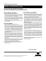
5. Disconnect the 6-pin connector plug. Using an AMP
extractor tool #458994-2 (NORDYNE #799092) remove
the blue wire from socket position #4 and install it in
position #1. (See Figure 1). If the tool is not available
proceed as follows:
Cut off the blue wire at socket position #4 in the connector,
as illustrated in Figure 1, and strip the insulation back
3/8”. Plug the length of blue wire provided into socket
position #1, next to the cut wire stub. Reconnect the
6-pin connector plug. Connect the loose ends of the blue
wires using the wire nut provided, as shown in Figure
2. Tape the wire nut connection with electricians tape.
6. Apply the new wiring diagram for G4 furnaces to the
inside of the control box cover.
7. Turn on the power
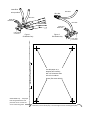
TEMPLATE ON BACK

All G4 & G5 Furnaces, except G5RL Models : Place this corner in corner of
control box, next to cutout (G4), or on lower-right corner of mounting panel (G5).
Use this paper as a
template and carefully
drill 3/16" diameter holes
in the four locations
shown (See notes below).
G5RL Models only : Fold paper
back along dashed lines and
place this corner on lower-left
corner of mounting panel.
G5RL Models: Fold back on line
Figure 1.
G4 Models Only
White Wire
Black Wire
Insert Blue
wire provided
Blue Wire
1
2
3
5
4
6
White Wire
Black Wire
Wire Nut
Blue Wire
Blue Wire
Figure 2.
G4 Models Only
6-Pin Wire
Connector
6-Pin Wire
Connector
-
 1
1
-
 2
2


Miller UTEC Replacement Control Kit Installation guide
- Type
- Installation guide
Ask a question and I''ll find the answer in the document
Finding information in a document is now easier with AI
Related papers
-
Intertherm Vent Alarm System for Sloped Roof Kit Installation guide
-
Intertherm M3RL Installation guide
-
Broan RG1 Installation guide
-
-
-
Broan M1SC 066 User manual
-
-
Broan M4R(C,L) Installation guide
-
-
Intertherm M2 Installation guide
Other documents
-
ICM Controls ICM2805A Installation guide
-
ICP H9MPT050F12B1 Installation guide
-
Nordyne M3RL User manual
-
-
Nordyne M1SC 066 User manual
-
-
FIELD CONTROLS S2020 Installation guide
-
Cozy BBT54 and User manual
-
Epson HWDV080DV(N User manual
-