Page is loading ...

MOSA div. della BCS S.p.A.
Viale Europa, 59 20090 Cusago (Milano) Italy
Tel.+39 - 0290352.1 Fax +39 - 0290390466 www.mosa.it
M A D E I N I T A L Y
Codice
Code
Code
Codigo
Kodezahl
Código
Код
Edizione
Edition
Édition
Edición
Ausgabe
Edição
Издание
• GruppoElettrogeno
• GeneratingSet
• GroupeElectrogene
• GruposElectrógenos
• Stromerzeuger
• GrupoGerador
• ГенераторнаяУстановка
740569003
GE 55 PS
09.2015
USE AND MAINTENANCE MANUAL
TRANSLATION OF THE ORIGINAL INSTRUCTIONS – ENGLISH
l a n g u a g e


M
0
REV.2-09/15
07/03/06 74056-GB
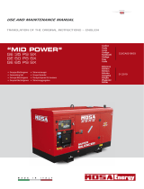
DESCRIPTION OF THE MACHINE
The generating set GE 55 is a unit which transforms the mechanical energy, generated by endothermic engine, into electric
energy, through an alternator.
Is meant for industrial and professional use, powered by an endothermic engine; it is composed of various main parts such as:
engine, alternator, electric and electronic controls, the fairing or a protective structure.
The assembling is made on a steel structure, on which are provided elastic support which must damp the vibrations and also
eliminate sounds which would produce noise.
ALTERNATOR
CANOPY
ROLL-BAR
FRONT PANEL
ENGINE
FUEL BASE

INDEX
M
1
REV.0-12/13
12/04/06 74056-GB
M 0 DESCRIPTION OF THE MACHINE
M 1.01 COPYRIGHT
M 1.1 NOTES
M 1.4 CE MARK
M 1.5 TECHNICAL DATA
M 2 - 2.1 SYMBOLS AND SAFETY PRECAUTIONS
M 2.6 INSTALLATION AND ADVICE
M 2.7 INSTALLATION
M 2.7.1 DIMENSIONS
M 3 UNPACKING
M 4.2... TRANSPORT AND HANDLING
M 20... SET-UP FOR OPERATION
M 21 START AND STOP
M 30 CONTROLS LEGEND
M 31 CONTROLS
M 32 CONTROLS
M 39.12 EP6 ENGINE PROTECTION
M 37 -….. USING THE GENERATOR
M 6.8 ASSEMBLY CTL
M 39.10 INSULATION MONITORING PROTECTION
M 38.6 TCM 35 REMOTE CONTROL
M 43 MAINTENANCE
M 40.2 TROUBLESHOOTING
M 45 STORAGE
M 46 CUST OFF
M 60 ELECTRICAL SYSTEM LEGENDE
M 61-….. ELECTRICAL SYSTEM

Copyright
M
1.01
REV.0-10/02
All rights are reserved to said Company.
It is a property logo of MOSA division of B.C.S. S.p.A.
All other possible logos contained in the documen-
tation are registered by the respective owners.
+ The reproduction and total or partial use, in any
form and/or with any means, of the documen-
tation is allowed to nobody without a written
permission by MOSA division of B.C.S. S.p.A.
To this aim is reminded the protection of the author’s
right and the rights connected to the creation and
design for communication, as provided by the laws
in force in the matter.
In no case MOSA division of B.C.S. S.p.A. will be
held responsible for any damaga, direct or indirect,
in relation with the use of the given information.
MOSA division of B.C.S. S.p.A. does not take any
responsibility about the shown information on rms
or individuals, but keeps the right to refuse services
or information publication which it judges discutible,
unright or illegal.
10/10/02 M1-01-GB
This use and maintenance manual is an important
part of the machines in question.
The assistance and maintenance personel must
keep said manual at disposal, as well as that
for the engine and alternator (if the machine is
synchronous) and all other documentation about
the machine.
We advise you to pay attention to the pages
concerning the security (see page M1.1).
ATTENTION
!

INFORMATION
Dear Customer,
We wish to thank you for having bought a high quality set.
Our sections for Technical Service and Spare Parts will
work at best to help you if it were necessary.
To this purpose we advise you, for all control and over-
haul operations, to turn to the nearest authorized Service
Centre, where you will obtain a prompt and specialized
intervention.
+ In case you do not prot on these Services and some
arts are replaced, please ask and be sure that are
used exclusively original parts; this to guarantee that
the performances and the initial safety prescribed by
the norms in force are re-established.
+The use of non original spare parts will cancel
immediately any guarantee and Technical Service
obligation.
NOTES ABOUT THE MANUAL
Before actioning the machine please read this manual
attentively. Follow the instructions contained in it, in this
way you will avoid inconveniences due to negligence,
mistakes or incorrect maintenance. The manual is for
qualied personnel, who knows the rules: about safety
and health, installation and use of sets movable as well
as xed.
You must remember that, in case you have difculties
for use or installation or others, our Technical Service is
always at your disposal for explanations or interventions.
The manual for Use Maintenance and Spare Parts is an
integrant part of the product. It must be kept with care
during all the life of the product.
In case the machine and/or the set should be yielded to
another user, this manual must also given to him.
Do not damage it, do not take parts away, do not tear
pages and keep it in places protected from dampness
and heat.
You must take into account that some gures contained in
it want only to identify the described parts and therefore
might not correspond to the machine in your possession.
INFORMATION OF GENERAL TYPE
In the envelope given together with the machine and/or
set you will nd: the manual for Use Maintenance and
Spare Parts, the manual for use of the engine and the
tools (if included in the equipment), the guarantee (in the
countries where it is prescribed by law).
The Manufacturer shall not be liable for ANY USE OF
THE PRODUCT OTHER THAN THAT PRECISELY
SPECIFIED IN THIS MANUAL and is thus not liable for
any risks which may occur as a result of IMPROPER
USE. The Company does not assume any liability for any
damage to persons, animals or property.
Our products are made in conformity with the safety
norms in force, for which it is advisable to use all these
devices or information so that the use does not bring
damage to persons or things.
While working it is advisable to keep to the personal safety
norms in force in the countries to which the product is
destined (clothing, work tools, etc.).
Do not modify for any motive parts of the machine (faste-
nings, holes, electric or mechanical devices, others..) if
not duly authorized in writing: the responsibility coming
from any potential intervention will fall on the executioner
as in fact he becomes maker of the machine.
Notes
M
1-1
REV.1-03/14
+ Notice: the manufacturer, who keeps the faculty,
apart the essential characteristics of the model here
described and illustrated, to bring betterments and
modications to parts and accessories, without putting
this manual uptodate immediately.
10/10/02 M1-1 GB_REV.1

CE MARKING
M
1.4
REV.7-02/14
10/10/02 M1-4 GB
Any of our product is labelled with CE marking attesting its conformity to appliable directives and
also the fulllment of safety requirements of the product itself; the list of these directives is part
of the declaration of conformity included in any machine standard equipment.
Here below the adopted symbol:
CE marking is clearly readable and unerasable and it can be either part of the data-plate.
Furthermore, on each model it is shown the noise level value; the symbol used is the following:
The indication is shown in a clear, readable and indeleble way on a sticker.
TEMP.
°CRPM
n
IP
kW
ALTIT.
Kg
m
G
P.F.
Hz
V(V)
I(A)
KVA
TYPE
I.CL.
SERIAL N°
Made in UE-ITALY
TYPE/N°
VOLTAGE(V)
POWER(W)
LTP POWER IN ACCORDANCE WITH ISO 8528
Pmax

GENERATOR
Stand-by three-phase power 51 kVA (40.8 kW) / 400 V / 73.6 A
PRP three-phase power 46 kVA (36.8 kW) / 400 V / 66.4 A
Stand by active power 17 kVA / 230 V / 73.9 A
Frequecy 50 Hz
Cos ϕ 0.8
* Output powers according to ISO 8528-1
ALTERNATOR self-excited, self-regulated, brushless
Type synchronous, three-phase
Insulation class H
ENGINE
Make / Model Perkins 1103A - 33TG1
Type / Cooling system Diesel 4-Stroke4 / Water
Cylinder / Displacement 3/ 3300 cm
3
Stand by net power 45.6 kW (62 HP)
PRP net power 41.3 kW (56.2 HP)
Speed 1500 rpm
Fuel consumption (75% of PRP) 8.2 l/h
Engine oil capacity 7.9 l
Starter Electric
* Powers according to ISO 3046-1
GENERAL SPECIFICATIONS
Battery 12V - 100Ah
Tank capacity 65 l
Running time (75% of PRP) 8 h
Protection IP 23
*Dimensions / max. on base Lxwxh 2030x870x1130
*Weight on base 940 kg
Measured acoustic power LwA (pressure LpA) 94 dB(A) (69 dB(A) @ 7 m)
Garanteed acoustic power LwA (pressure LpA 95 dB(A) (70 dB(A) @ 7 m)
* Dimensions and weight are inclusive of all parts.
TECHNICAL DATA
04/05/06 74056-GB
M
1.5
REV.2-09/15
2000 / 14 / CE
OUTPUT
Declared power according to ISO 8528-1 (temperature 40°C, 30% relative humidity, altitude 1000 m above sea level).
(*Stand-by) = maximum available power for use at variable loads for a yearly number of hours limited at 500 h. No overload is
admitted.
(**Prime power PRP) = maximum available power for use at variable loads for a yearly illimited number of hours. The average
power to be taken during a period of 24 h must not be over 80% of the PRP.
It’s admitted overload of 10% each hour every 12 h.
In an approximative way one reduces: of 1% every 1000 m altitude and of 3% for every 5°C above 40°C.
ACOUSTIC POWER LEVEL
ATTENTION: The concrete risk due to the machine depends on the conditions in which it is used. Therefore, it is up to the end-
user and under his direct responsibility to make a correct evaluation of the same risk and to adopt specic precautions (for
instance, adopting a I.P.D. -Individual Protection Device)
Acoustic Noise Level (LWA) - Measure Unit dB(A): it stands for acoustic noise released in a certain delay of time. This is not
submitted to the distance of measurement.
Acoustic Pressure (Lp) - Measure Unit dB(A): it measures the pressure originated by sound waves emission. Its value changes
in proportion to the distance of measurement.
The here below table shows examples of acoustic pressure (Lp) at different distances from a machine with Acoustic Noise Level
(LWA) of 95 dB(A)
Lp a 1 meter = 95 dB(A) - 8 dB(A) = 87 dB(A) Lp a 7 meters = 95 dB(A) - 25 dB(A) = 70 dB(A)
Lp a 4 meters = 95 dB(A) - 20 dB(A) = 75 dB(A) Lp a 10 meters = 95 dB(A) - 28 dB(A) = 67 dB(A)
PLEASE NOTE: the symbol
2000 / 14 / CE
when with acoustic noise values, indicates that the device respects noise emission limits
according to 2000/14/CE directive.

WARNINGS
M
2
REV.1-02/14
The installation and general warnings regarding operations are aimed achieving correct use of the machine and/or
apparatus in the place where it is used as a genset and/or motor welder.
- Advice to the User about the safety:
+ NB: The information contained in the manual can be changed without notice.
Any damage caused in connection with the use of these instructions shall not be considered as they are only
indicative.
Remember that the non observance of the indications reported by us might cause damage to persons or
things. It is understood, that local dispositions and/or laws must be respected.
10/06/00 M2GB
This heading warns of an immediate danger for persons
as well for things. Not following the advice can result in
serious injury or death.
This heading warns of situations which could result in
injury for persons or damage to things.
To this advice can appear a danger for persons as well
as for things, for which can appear situations bringing
material damage to things.
These headings refer to information which will assis you
in the correct use of the machine and/or accessories.
DANGEROUS
!
WARNING
!
CAUTION
!
IMPORTANT
!
NOTE
!
ATTENTION
!
+ FIRSTAID. In case the operator shold be sprayed by accident, from corrosive liquids a/o hot toxic gas
or whatever event which may cause serious injuries or death, predispose the rst aid in accordance
with the ruling labour accident standards or of local instructions.
+ FIREPREVENTION. In case the working zone,for whatsoever cause goes on re with ames liable to
cause severe wounds or death, follow the rst aid as described by the ruling norms or local ones.
Skin contact Wash with water and soap
Eyes contact Irrigate with plenty of water, if the irritation persists contact a specialist
Ingestion Do not induce vomit as to avoid the intake of vomit into the lungs, send for a doctor
Suction of liquids from
lungs
If you suppose that vomit has entered the lungs (as in case of spontaneous vomit) take the subject to the
hospital with the utmost urgency
Inhalation In case of exposure to high concentration of vapours take immediately to a non polluted zone the person involved
EXTINCTIONMEANS
Appropriated Carbonate anhydride (or carbon dioxyde) powder, foam, nebulized water
Not to be used Avoid the use of water jets
Other indications Cover eventual shedding not on re with foam or sand, use water jets to cool off the surfaces close to the re
Particular protection Wear an autorespiratory mask when heavy smoke is present
Useful warnings Avoid, by appropriate means to have oil sprays over metallic hot surfaces or over electric contacts
(switches,plugs,etc.). In case of oil sprinkling from pressure circuits, keep in mind that the inamability
point is very low.

SYMBOLS AND SAFETY PRECAUTIONS
M
2-1
REV.2-06/10
SYMBOLS
STOP - Read absolutely and be duly attentive
Read and pay due attention
GENERAL ADVICE - If the advice is not
respected damage can happen to persons or
things.
HIGH VOLTAGE - Attention High Voltage.
There can be parts in voltage, dangerous
to touch. The non observance of the advice
implies life danger.
FIRE - Danger of ame or re. If the advice is
not respected res can happen.
HEAT - Hot surfaces. If the advice is not
respected burns or damage to things can be
caused.
EXPLOSION - Explosive material or danger
of explosion. in general. If the advice is not
respected there can be explosions.
WATER - Danger of shortcircuit. If the advice
is not respected res or damage to persons
can be caused.
SMOKING - The cigarette can cause re or
explosion. If the advice is not respected res
or explosions can be caused.
ACIDS - Danger of corrosion. If the advice is
not respected the acids can cause corrosions
with damage to persons or things.
WRENCH - Use of the tools. If the advice is
not respected damage can be caused to things
and even to persons.
PRESSION - Danger of burns caused by the
expulsion of hot liquids under pressure.
PROHIBITIONS No harm for persons
Use only with safety clothing -
It is compulsory to use the personal
protection means given in equip-
ment.
Use only with safety clothing -
It is compulsory to use the personal protection
means given in equipment.
Use only with safety protections -
It is a must to use protection means suitable for
the different welding works.
Use with only safety material -
It is prohibited to use water to quench res on
the electric machines.
Use only with non inserted voltage -
It is prohibited to make interventions before
having disinserted the voltage.
No smoking -
It is prohibited to smoke while lling the tank
with fuel.
No welding -
It is forbidden to weld in rooms containing
explosive gases.
ADVICE No harm for persons and things
Use only with safety tools, adapted to the specic
use -
It is advisable to use tools adapted to the various
maintenance works.
Use only with safety protections, specically suitable
It is advisable to use protections suitable for the
different welding works.
Use only with safety protections -
It is advisable to use protections suitable for
the different daily checking works.
Use only with safety protections -
It is advisable to use all protections while
shifting the machine.
Use only with safety protections -
It is advisable to use protections suitable for
the different daily checking works.and/or of
maintenance.
!
26/11/99 M2-1GB
ACCES FORBIDDEN to non authorized peaple.

General installation criteria
Installation of a genset has to be planned by qualied and
trained technicians, it has to be carried out by a competent
organization with qualied personnel and proper equip-
ment.
Before proceeding with installation the following condi-
tions have to be checked:
• Genset has been selected according to needs of
the electrical load and to environmental conditions
(temperature, altitude and humidity);
• Genset location is of appropriate dimensions and
allows accessibility to genset for maintenance and/
or necessary repairs;
• If genset is indoors, ensure there is enough air for
engine combustion, for genset cooling (radiator and
generator), and sufcient ventilation;
• If genset is indoors, a system of expulsion for engine
exhaust gas is provided;
• Personnel safety has been carefully considered;
• Noise-level issues have been carefully considered;
• Fuel and lubricant stocking issues have been
considered in accordance to norms in force in the
country of installation.
ATTENTION
Faulty installation can create damage to the genset
and the User system, and injury to persons.
It is compulsory to install the genset according to the
norms in force in the country of installation.
The installing company must provide a conformity de-
claration stating that installation has been carried out
duly and according to plans and to norms in force.
ATTENTION
All generating sets are equipped with a control system
that is NOT inuenced by standard environmental fac-
tors and is able to stop the unit in case of anomalous
values in the fundamental parameters.
In order to avoid unexpected black-outs or other po-
tentially dangerous situations, the below installation
indications must be followed.
INFORMATION
Italian and European norms dene specic characteri-
stics referring to the premises in which genset should
be located, indicating possible positioning, minimum
dimensions, etc.
For any doubt referring to installation location contact
our technical sales ofce.
!
!
Installationinstructions
M
2.6
REV.0-06/10
Environmental conditions
ATTENTION
Open gensets (SKID) have to be located in an area
protected from rain, snow, high humidity and direct
exposure to the sun.
Rain or high humidity on GE genset alternator, in par-
ticular during operation, cause an increase in volta-
ge output, winding faults, electric discharge towards
ground, with damage to the genset and injury to per-
sons. Dust, in particular saline dust, must be avoided.
In case radiator or air lters are obstructed, there is the
risk that genset will overheat or be damaged. Aspira-
tion grills must not be obstructed by leaves, snow, etc.
!
Output of fumes in open air conditions
DANGER
Genset must be positioned so that exhaust gas is dif-
fused without being inhaled by any living being.
Engine exhaust gas contains carbon monoxide, which
is harmful to one’s health, and in big quantities can
cause intoxication and death.
Local norms in force have to be respected.
!
Outdoor installation
02/06/10 84306-GB

Safe distance
Fixing
In order to absorb vibrations produced by genset, it
should be xed to a surface with sufcient rigidity, isola-
ted against vibrations towards other structures and with
a mass equal to at least three times the genset mass.
DO NOT locate the genset on terraces or raised levels,
if its characteristics have not been previously veried as
suitable.
ATTENTION
A safe distance has to be kept between genset and
fuel deposits, inammable goods (cloths, paper, etc.),
chemicals, according to indications provided by the
authority in charge. In order to avoid potentially dan-
gerous situations, area surrounding genset should be
isolated so that unauthorized people will not be able
to get close to the unit. Even if MOSA gensets are ma-
nufactured according to electromagnetic compatibility
norms, we suggest NOT to install the genset near ma-
chinery that can be inuenced by magnetic elds.
NOTE
When using a genset it is advisable to adopt pre-
cautions to avoid that fuel, lubricant and other en-
gine liquids may accidentally cause soil pollution.
The most recent generators are designed to retain
possible liquid leakages, hence no specic mea-
sures are needed in this regard.
In case of doubts concerning your genset do not
hesitate to contact our technical sales ofce.
Installationinstructions
!
!
M
2.6.1
REV.0-06/10
ATTENTION
Engine and alternator when in operation produce heat:
• Shelter should NOT obstruct normal cooling of com-
ponents;
• Exhaust gas should be directed in order to avoid the
possibility that alternator and engine fan inhale it;
• Shelter should be made of reproof material, as em-
bers may come out of the exhaust pipe;
• Never cover or wrap up genset with plastic sheets or
other material while operating. If genset is off, make
sure engine has cooled before you cover it, or else
there may be risk of damage to the genset or may
catch re.
!
Temporary outdoor installation
Indications given for xed installation have to be follo-
wed.
If genset is not positioned correctly, vibrations transmit-
ted to the baseframe may cause the genset to move,
this may occur while the genset has a load inserted,
take on all necessary precautions to avoid this.
LA=LARG. G.E.
LA=WIDTH G.S.
LA=LARGEUR G.E.
LA=LARGO G.E.
Sample of outdoor installation with shelter
02/06/10 84306-GB
Fixed outdoor installation
If a shelter is used to protect the genset (see gure), it
should NOT be attached to it.
Even if a shelter is temporary the below indications
should be followed:

Installationinstructions
M
2.6.2
REV.0-06/10
H=ALTEZZA G.E.
H=HEIGTH G.S.
H=HAUTEUR G.E.
H=ALTEZA G.E.
Indoor installation
In order to avoid endangering or damaging genset fol-
lowing indications must be followed.
Genset installation location has to be in accordance to
the norms in force.
ref. Description
1 Generating set
2 Auxiliary aspirator
5 Exhaust pipe
7 Exhaust pipe protection and insulation
8 Raincover and anti-intrusion grid
9 Exhaust conduit
11 Location area with isolated foundation
12 Air inlet with anti-intrusion grid
13 Entrance door
14 Containment step
Minimum suggested dimension table
A Length G.E. + 1000 mm
B Width G.E. + 2000 mm
C Width G.E. + 200 mm
D Length G.E. + 400 mm
E Width G.E. + 400 mm
H Height G.E. + 1500 mm (>2500 mm)
Note: dimensions required by norms in force have to
be respected in any case.
Surface area
The best solution is to create a base isolated from the
rest of the structure, on which the genset will be located,
in order to avoid vibrations being transmitted.
The base must be built with reinforced concrete and the-
re must be the possibility to x the genset to it by using
screw anchors or rag bolts.
Base dimensions should exceed genset dimensions of
at least 200 mm on each side. Base should weigh three
times static genset weight (indicated on the technical
date).
Floor should be levelled and suitable to sustain genset
weight.
Thresholds on doors and openings should have a barrier
in order to avoid liquids leaking. In case it is not possible
to provide a door with a barrier, the genset should have
a collection base appropriate for the quantity of liquid
it contains, in any case dimensions of collection base
must be in accordance to the laws in force in country of
installation.
Room openings and ventilation
The room should have a ventilation system sufcient
enough to avoid stagnation and circulation of overhe-
ated air.
Openings for incoming and outgoing air should be of
appropriate size, considering minimum required air ow
and maximum back pressure, values that can be che-
cked on the engine manual.
Opening for the air entrance should be near the back
part of the genset as close as possible to the ground.
If openings for air ow are not aligned with genset it may
be necessary to add air conduits to avoid any air disper-
sion (see gure).
02/06/10 84306-GB
Sample of outdoor installation with shelter

Installationinstructions
M
2.6.3
REV.0-06/10
For open gensets installed indoors, we recommend:
• The dimensions of the air outlets be such that they
have at least the same area of the radiator;
• the dimensions of the windows for air outlet is at
least on the surface of the radiator.
• The dimensions of the air inlets be such that they
have at least the same area of the radiator +10% for
gensets up to 130 kVA or +25% for gensets beyond
130 kVA;
For canopied gensets installed indoors, we recommend:
• The dimensions of the air outlets be such that they
have at least the same area of the generator air out-
lets, as indicated at page M2.7 of the present ma-
nual;
• The dimensions of the air inlets be such that they
have at least the same area of the generator air in-
lets, as indicated at page M2.7 of the present ma-
nual +10% for gensets up to 130 kVA or +25% for
gensets beyond 130 kVA;
The opening area has to be calculated considering pro-
tection grill surface, in order to insure that remaining free
area is sufcient.
Dimensions of openings calculated as above indica-
ted, are the minimum acceptable dimensions in case
of L.T.P. use; the pressure remaining after radiator and
back pressure must be considered while planning di-
mensions of the piping.
To calculate the opening section check below drawing:
WARNING: to avoid reux of heated air and loss of load,
add an air duct between radiator and opening.
To consider the correct quantity of heat to be dischar-
ged, loss of heat on duct should be evaluated. If the duct
is not appropriately insulated, room-temperature may in-
crease considerably, for this reason it may be necessary
to install an electro ventilator for correct air exchange.
a Radiator surface
b Free opening
c
Air ow opening with grill and 80% of open
surface
d Air ow opening with bafe plates
Electro ventilator capacity can be calculated as follows:
ATTENTION
Exhaust piping may reach up to 600 °C during
operation, therefore it is compulsory to cover pi-
ping with appropriate insulation.
!
02/06/10 84306-GB
Fan Capacity [m
3
/h]=
Transmitted heat [Kcal/h]
0,287
x ∆t [°C]
Considering:
• heat to radiation is indicated on engine/alternator
technical data sheet;
• 0. 287 is specic heat for each m3 of air at 20°C;
• Δt in °C is usually considered as equal to 5 °C
(worst conditions are considered).
Exhaust piping
Exhaust piping must be built in accordance to laws in
force in the country of installation.
General indications:
• Minimum required thickness: 2.0 mm;
• Diameter of piping has to be calculated considering,
length, number of bends, type of exhaust mufer,
and any other accessory used on it. Back pressure
should not exceed values provided by manufac-
turer, as this causes loss of power and damage to
the engine.
DANGER
Engine exhaust gas contains carbon mono-
xide, harmful to health and in large quantities
can cause intoxication or death.
• Exhaust piping should be composed of parts, con-
nected by anges with gaskets, for easy disassem-
bling and grant maximum tightness.
• Exhaust piping should be connected to engine by a
ex that should absorb dilatation and separate x part
from engine piping.
• Exhaust piping should not weigh on engine manifold.
!

INSTALLAZIONE
INSTALLATION
INSTALLATION
04/05/06 74056-I
D
E
NL
LUFTZIRCULATION M
2.7
REV.0-05/06

02/05/13 84030-I
73557. 5
30
1130
870
ø13
1640175
2030
ø13 n° 4 for i
Dimensioni
Dimensions
Dimensions
GE 35 PSX - 55 PS
DSP 600 PSX
M
2.7.1
REV.1-05/08
Abmessungen
Dimensiones
D
E
NL

NOTE
UNPACKING
M
3
REV.1-02/04
!
+ Be sure that the lifting devices are: correctly mounted,
adequate for the weight of the machine with it’s pack-
aging, and conforms to local rules and regulations.
When receiving the goods make sure that the product
has not suffered damage during the transport, that
there has not been rough handling or taking away of
parts contained inside the packing or in the set.
In case you nd damages, rough handling or absence
of parts (envelopes, manuals, etc.), we advise you to
inform immediately our Technical Service.
For eliminating the packing materials, the User
must keep to the norms in force in his country.
1) Take the machine (C) out of the shipment packing.
Take out of the envelope (A) the user’s manual (B).
2) Read: the user’s manual (B), the plates xed on the
machine, the data plate.
30/03/00 M3GB
2
B
A
1
C

General precautions when handling the machine.
To limit the dangers involved in moving a generating set,
it is important to carefully follow the guideline set out
below:
• Transportation must always take place with the en-
gine off and electrical cables and starting battery di-
sconnected and fuel tank empty.
• Particular attention must be paid to SKID version ge-
nerating sets (without canopy) that have very delicate
parts unprotected from bumps (injection pump, speed
regulator, radiator, electrical panel connections and
instrumentation).
• Generating sets must be protected from bad weather
during transport: the units must be entirely covered,
especially the electrical parts (alternator and control
panel).
• Some engine parts retain heat even after it has been
shut off: therefore it is necessary to wait for the engi-
ne to cool before covering it to avoid the risk of re.
• Clear the moving zone of all possible obstacles and
from all unnecessary personnel.
• Use properly sized lifting equipment regularly submit-
ted to major overhaul by an authorized organisation.
It is prohibited to fasten objects or accessories on the
generating set baseframe that may modify weight
and center of gravity and may cause movements un-
foreseen by the lifting eyes.
• Do not subject the generating set and lifting equip-
ment to abrupt or undulating movements that pass on
stress dynamics to the structure.
• Do not lift the generating set higher than what is ab-
solutely necessary.
• Transportation of separate manual or automatic con-
trol panels must be carried out very carefully in order
to avoid damage to the equipment contained inside
the panel and to the instruments on the front.
• To access the hook points on the top of the unit, use
approved ladders only or support from another opera-
tor: climb the ladder using non-skid shoes.
ATTENTION
When moving/lifting a genset it is imperative to be
extremely careful. All moving operations must be
carried out be qualied persons.
Due to the weight and encumbrance of the genset,
an error while moving/lifting the unit may cause
serious damage to it or surrounding persons.
Moving method
The generating sets are lifted with different methods ac-
cording to the unit’s conguration. Below are the main
methods of moving/lifting the genset.
Moving the generating set via forklift
When lifting with a forklift it is necessary to fork the ba-
seframe sideways so that the forks stick out from one
side to the other side, widening them to distribute the
weight properly, maintaining the genset level.
Stickers on the base indicate where to place the lifter
forks.
Transport and handling
I
GB
F
!
M
4.2
REV.0-06/10
Moving the generating set via cables or chains
When lifting the genset with the aid of cables or chains it
is necessary to use equipment periodically checked by
a licensed organisation. Hook the cables only on to the
points provided for this use and shown via the appro-
priate stickers.
For correctly moving the generating set:
• DO NOT lift the genset by fastening cables to the lif-
ting eyes on the engine or alternator (these are only
used for lifting the single components).
• DO NOT make abrupt or undulating movements that
pass on stress dynamics to the structure.
• DO NOT leave the generating set suspended for lon-
ger than absolutely necessary to move the unit.
• Use all the lifting eyes provided.
• Use cables and/or chains of equal length so that the
weight is distributed evenly.
02/06/10 M4-GB_COF

Transport and handling
I
GB
F
M
4.2.1
REV.0-06/10
Moving by site trolley / trailer
Trolleys/trailers should only be used to move the gene-
rating set for which they were designed.
Road trolley CTV:
BEWARE
DO NOT TOW the generating set without trailer, be
it manually or using a vehicle.
!
made by using a general use standard trailer on which
the genset is xed: it is type approved for transport on
public roads by licensed organisations. The maximum
speed allowed is 80 km/h however, the transportation
laws in force in the place of use should be respected.
02/06/10 M4-GB_COF
Moving the generating set via cables or chains
Site tow CTL:
this trailer is made by the manufacturer and connected
to the generating set baseframe, it can not be towed on
public roads. Therefore it can only be used on private
roads and no through trafc zones.
The maximum speed allowed is 40 km/h on smooth sur-
faces (asphalt, cement) and, in any case, the laws in
force in the place of use should be respected.
Always follow the directions below for any tipe of tow:
• DO NOT park the generating set/trolley assy, on slant
ground
• When parking always use the emergency/hand brake
and/or safety clamps.
• DO NOT tow the trailer on bumpy roads.
Moving the unit via motor vehicle
During transportation with a motor vehicle, it is important
to use appropriate belts/straps to stabilise the unit, the-
refore avoiding that unexpected bumps or jolts can cau-
se damage to the baseframe, engine, or worse, over-
turn the load. It is the carrier’s responsibility to always
respect the highway code in force.
OK

Set-up for operation Water cooled systems
M
20
REV.2-04/15
12/06/03 M20-R-HO2-GB
The manufacturer recommends selecting
engine oil.
Refer to the label on the motor for the recommended
products.
Please refer to the motor operating manual for the
recommended viscosity.
Carry out refuelling and controls with motor at level
position.
1. Remove the oil-ll tap (24)
2. Pour oil and replace the tap
3. Check the oil level using the dipstick (23); the oil
level must be comprised between the minimum
and maximum indicators.
Check that the dry air lter is correctly installed and
that there are no leaks around the lter which could
lead to inltrations of non-ltered air to the inside of
the motor.
The starter battery is supplied
already charged and ready for
use.
Before starting the gen-set con-
nect the cable + (positive) to the
pole + of the battery, by properly
tightening the clamp. In case of models with war-
ning light: check the state of the battery by means
of the indicator placed in the upper part.
- Green colour: battery OK
- Black colour: battery to be recharged
- White colour: battery to be replaced
Rell the tank with good quality diesel fuel, such as
automobile type diesel fuel, for example.
For further details on the type of diesel fuel to use,
see the motor operating manual supplied.
Do not ll the tank completely; leave a space of
approx. 10 mm between the fuel level and the wall
of the tank to allow for expansion.
In rigid environmental temperature conditions, use
special winterized diesel fuels or specic additives
in order to avoid the formation of parafn.
Stop engine when fueling. Do not smoke
or use open ames during refuelling
operations, in order to avoid explosions
or re hazards.
Fuel fumes are highly toxic; carry out
operations outdoors only, or in a well-
ventilated environment.
Avoid accidentally spilling fuel. Clean
any eventual leaks before starting up
motor.
!
It is dangerous to ll the motor with too much oil,
as its combustion can provoke a sudden increase
in rotation speed.
!
/