Page is loading ...

FIRST EDITION
A
A
A
SSEMBLY
SSEMBLY
SSEMBLY
I
I
NSTRUCTIONS
NSTRUCTIONS
/
/
O
O
O
WNERS
WNERS
WNERS
M
M
ANUAL
ANUAL
Part No. 06005 Revision: A Date: 12 / 04
U
U
NIVERSAL
NIVERSAL
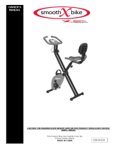
LS 760
LS 760
R
R
ECUMBENT
ECUMBENT
E
E
XERCISE
XERCISE
BIKE
BIKE

IMPORTANT PRECAUTIONS
WARNING: To reduce the risk of injury, please read the following precautions before assembling or using your new product.
1. It is the responsibility of the owner to ensure that all users of this equipment are adequately informed of stated precautions.
2. Read all instructions and enclosed literature carefully. Understand the assembly and operation before using the equipment.
3. Use equipment on a flat level surface. Use adjustment levelers on the bottom of equipment to help stabilize unit.
4. It’s recommended to place an exercise / product mat beneath the equipment for added protection of floors or carpets.
5. Keep children & pets away from equipment at all times. Unplug equipment for added safety while not in use.
6. Inspect product on a frequent basis. Tighten lose assemblies or hardware as needed. Replace worn or damaged parts.
7. This equipment is intended for internal home use only. Do not use in a non-residential environment. Use in non-recommended
environments can lead to serious injury and will void all related warranties & liabilities.
8. Recommended user weight should not exceed 300 lbs.
9. Frequently wipe equipment down with a dampened soft cloth.
10. Observe and adhere to all warning labels posted on equipment.
11. Properly warm-up and stretch before starting any strength training or cardio exercise routine.
12. If you feel pain or dizziness at any time while exercising, stop immediately and consult your physician.
Safety Warning: Before starting an exercise program, consult your physician. This is especially important for individuals over the
age of 35 or persons with pre-existing health problems. It’s important to read all instructions carefully. We assume no responsibility
for personal injury or consequential damages sustained by or through the use of this equipment. Additional terms & conditions are
listed in the back of this manual or enclosed owners manual.
PAGE 1
TABLE OF CONTENTS
Reference Information Page
Assembly Prep / Intro 2
Parts List 3
Product Exploded View 4
Product Assembly Instruction 5-11
Computer Operation 12-14
Troubleshooting 15
Preventative Maintenance 16
Warranty Terms 17
Product Registration 18

ASSEMBLY PREPARATION / INTRO
PAGE 2
P
RODUCT ASSEMBLY
Assembly Prep:
♦ To ensure ease of product assembly, please take time to verify the size and quantities of all
required assembly hardware. Use the itemized parts listing and hardware chart for reference.
♦ The product assembly process has been documented in easy to follow stages. Please read all
assembly instructions carefully. Take time to review the manual and familiarize yourself
with the entire assembly process before proceeding. Assembly Tip: It is always helpful to
pre-stage the items needed for each assembly step.
♦ Perform product assembly in a 4ft. x 6ft. flat area. Note: After assembly is completed, allow
a minimal of 2-3ft. of space on each side of bike for user access and dismounting.
♦ The basic tools for assembling this product are included with main assembly hardware.
♦ Do not dispose of any packaging materials until assembly of the product is completed.
♦ If you experience problems with operation of the equipment after assembly, please review
the troubleshooting reference page in this manual.
♦ Make sure to completely fill-out the product registration form & return it to us within
30-days of purchase.
♦ For added component life, follow the preventative maintenance tips listed in this manual.
♦ Please contact us if have additional questions or need service assistance (877.861.2181)

PARTS REFERENCE
PAGE 3
LS 760 Assembly Parts List
Item # Part Number Description QTY.
1 23010 Main Base Assembly 1
2 23000 Front Stabilizer Assembly 1
3 05014 Left Pedal 1 (pr.)
4 05014 Right Pedal 1 (pr.)
5 23004 Rear Stabilizer Assembly 1
6 13016 Seat Rail Support 1
7 13013 Seat Rail 1
8 05018 Cap / Cover 1
9 13002 Handlebar Assembly 1
10 13006 Seat Frame 1
11 03004 Seat 1
12 03008 Back Pad 1
13 13002 Magazine Rack 1
14 23017 Handlebar Mast 1
15 03012 Handlebar (H-shaped) 1
16 07010 Cover (Handlebar Mast) 1
17 10004 Computer 1
18 12007 Upper Heart Rate Sensor Cable 1
19 12001 Lower Heart Rate Sensor Cable 1
20 12011 Upper Data Cable Assembly 1
21 12009 Lower Data Cable Assembly 1
22 12002 Heart Cable (Seat Rail) 1
23 05001 Adjustment Knob 1
24 01062 Carriage Bolt M8 x 1.25 x 55 Length 4
25 01012 Flat Washer 8 x 16 x 2t 29
26 01015 Acorn Nut M8 4
27 01059 Leveler 2
28 01016 Hex Nut 2
29 01045 Truss Screw (Magazine Rack Mounting) 3
30 01001 Truss Head Hex Socket Screw 8
31 01003 Truss Head Hex Socket Screw 23
32 01049 Curved Washer 8 x 19 x 2t 6
33 01041 Truss Screw (Computer Mounting) 4
34 01043 Truss Screw (Sports Bottle Mounting) 2
35 31001 Bottle Cage 1
36 31000 Sports Bottle 1
37 14001 AC Adapter 1
NOTE: Most of the listed assembly hardware has been packaged separately, but some hardware items have
been preinstalled in the identified assembly parts. In these instance, simply remove and reinstall the hardware as
assembly is required. Please reference the individual assembly steps and make note of all preinstalled hardware.

EXPLODED VIEW
PAGE 4
12
11
17
14
15
1
10
13
6
7
16
2
5
8
9
3
4
31
25
31
32
35
34
36
18
20
19
21
23
25
30
25
31 30
25
32
31
22
31
25
26
25
24
25
31
29
33
28
27
37
LS 760 Assembly Parts
25
31
AC Power Adapter
Customer Service 1-877-861-2181

ASSEMBLY STAGE #1
Assemble Seat Pads & Handlebar Assembly to the Seat Frame
Assembly Hardware Required: (*Hardware may be preinstalled)
#30 Truss Head Hex Socket Screw Qty. 8 #25 Flat Washers Qty. 12
#31 Truss Head Hex Socket Screw Qty. 4 #29 Truss Screw* Qty. 3
Assembly Description:
A) Attach the Handlebar Assembly (#9) to the Seat Frame (#10) using 4-Truss Head Socket Screws (#31)
and 4– Flat Washers (#25). (Reference Step #1 on the enclosed hardware pack)
B) Fasten the Back Pad (#12) to the Seat Frame using 4-Truss Head Sockets Screws (#30) and 4-Flat
Washers (#25). (Reference Step #2 on the enclosed hardware pack).
C) Fasten the Seat (#11) to the Seat Frame (#10) using 4-Truss Head Socket Screws (#30) and 4-Flat
Washers (#25). (Reference Step #3 on the enclosed hardware pack)
D) Assemble the Magazine Rack (#13) to the back of the Seat Back (#12) using *3-Truss Screws (#29).
( Note: If assembly hardware is not preinstalled, reference Step #4 on the enclosed hardware pack).
E) Thread the Adjustment Knob (#23) into the Seat Frame (#10). Note: It is not necessary to fully tighten
the knob into the Seat Frame at this point.
♦ Assembly Stage #1 complete
ASSEMBLY INSTRUCTION
P
AGE 5
11
12
13
31
25
29
25
30
23
9
USE TOOL

ASSEMBLY STAGE #2
Attach Front Stabilizer & Pedals to the Main Base
Assembly Hardware Required:
#24 Carriage Bolt Qty. 2
#25 Flat Washer Qty. 2
#26 Acorn Nut Qty. 2
Assembly Description:
A) Securely fasten the Front Stabilizer Assembly / with transport wheels (#2) to the Main Base (#1) using
2-Carriage Bolts (#24), 2–Flat Washers (#25), and 2-Acorn Nuts (#26). (Reference Step #5 on the
enclosed hardware pack)
B) Assemble the Right Pedal (#4) to the Right Crank Arm on the Main Base Assembly (#1). Thread the
pedal on the crank arm and then securely tighten with the pedal wrench. Note: A counterclockwise rotation
will tighten the pedal to the crank arm and a clockwise rotation will loosen the pedal. (*See Note Below)
C) Assemble the Left Pedal (#3) to the Left Crank Arm on the Main Base Assembly (#1). Thread the pedal
onto the crank arm (counterclockwise) and then securely tighten with the pedal wrench. Note: A clockwise
rotation will tighten the pedal to the crank arm and a counterclockwise rotation will loosen the pedal.
(*See Note Below)
D) Attach Pedal Straps (included with pedals) to each of the pedals. The straps are labeled (R) or (L) to
correspond with the right and left pedal.
*Important Assembly Note: The right and left pedals are appropriately marked (R) and (L). The threading
orientation on the left pedal is reversed from the threading orientation on the right pedal. To avoid stripping
of the threads on the pedals or crank arms make sure to follow the noted assembly orientation.
♦ Assembly Stage #2 completed
ASSEMBLY INSTRUCTION PAGE 6
3
4
1
24
26
25
2
L
R
USE TOOLS
Use This End to Tighten the Pedals
Note: Transport Wheels Face Away From the Main Base

ASSEMBLY STAGE #3
Attach Rear Stabilizer & Seat Rail Support to the Main Base
Assembly Hardware Required:
#24 Carriage Bolt Qty. 2 #31 Truss Head Hex Socket Screw Qty. 3
#25 Flat Washer Qty. 3 #32 Curved Washer Qty. 2
#26 Acorn Nut Qty. 2
Assembly Description:
A) Attach the Rear Stabilizer Assembly (#5) to the Seat Rail Support (#6) using 2-Carriage Bolts, 2-Flat
Washers (#25), and 2-Acorn Nuts (#26). (Reference Step #7 on the enclosed hardware pack)
B) Place the Cap / Cover (#8) over the end of the Seat Rail Support (#6) and slide the open end of the Seat
Rail Support over the lower frame extrusion of the Main Base (#). Secure in place using 3-Truss Head
Hex Socket Screws (#31), 2-Curved Washers (#32), and 1-Flat Washer (#25), but do
not fully tighten
the hardware until the further assembly of the Seat Rail is completed. (Reference Step #8 on the enclosed
hardware pack)
Note: Use the Adjustment Levelers (#27) on the Rear Stabilizer Assembly (#5) to prevent the base unit
from rocking on an uneven surface. (Reference Figure #1)
♦ Assembly Stage #3 completed
ASSEMBLY INSTRUCTION PAGE 7
31
25
31
32
1
6
5
26
25
24
8
ADJUSTMENT LEVELER
USE TOOLS
Figure #1
27

ASSEMBLY STAGE #4
Attach Seat Rail & Seat Assembly to the Main Base
Assembly Hardware Required:
#31 Truss Head Hex Socket Screw Qty. 8 #25 Flat Washer Qty. 8
Assembly Description:
A) Slide the Seat Rail (#7) through the sleeve insert of the Seat Frame (#10) (Reference Figure #2).Note: Be
careful not to damage the Seat Rail / Heart Rate Cable (#22).
B) Once the Seat Rail has been inserted through the Seat Frame sleeve, center the Seat Frame in the middle of
the Seat Rail and use the Adjustment Knob (#23) to lock the seat in position. Note: After the Seat frame
is locked into position hole, turn the knob (clockwise) to securely
lock the Seat Frame in place.
C) Rest the Seat Rail assembly on back end of the Seat Support mounting plate. Connect the Seat Rail /
Heart Rate Cable (#22) to the Lower Heart Rate Cable (#19), as shown.
D) Tuck excess cable length inside the Seat Rail and slide the front end of the Seat Rail over the end of the
middle extrusion of the Main Base (#1). Note: Be Careful not to damage the heart rate cables. Secure the
Seat Rail in place using 4-Truss Head Hex Socket Screws (#31) and 4-Flat Washers (#25), but do
not
fully tighten the mounting hardware. (Reference Step #10 on the enclosed hardware pack)
E) Align the Seat Rail rear mounting holes with the Seat Support mounting plate. Secure the Seat Rail in
place using 4-Truss Head Hex Socket Screws (#31) and 4-Flat Washers (#25). (Reference Step #11 on
the enclosed hardware pack)
F) Securely tighten all
the hardware used to assemble the Seat Support (#6) and Seat Rail (#7) to the
Main Base, including the assembly hardware located under the Cap / Cover (#8).
G) Plug the Seat Rail / Heart Rate Cable (#22) into the receptacle located on the back of the Handlebar
Assembly (#9). (Reference Figure #3)
♦ Assembly Stage #4 completed
ASSEMBLY INSTRUCTION PAGE 8
1
31
25
25
31
19
22
22
23
7
Figure #2
Figure #3
USE TOOL
8
9

ASSEMBLY INSTRUCTION
ASSEMBLY STAGE #5
Attach Handlebar & Handlebar Mast to the Main Base
Assembly Hardware Required: (*Hardware preinstalled)
#31 Truss Head Hex Socket Screw* Qty. 8 #32 Curved Washer* Qty. 4
#25 Flat Washer Qty. 4
Assembly Description:
A) Remove the preinstalled hardware from the mast mounting area of the Main Base.
B) Slide the Mast Cover (#16) over the lower end of the Handlebar Mast (#14). Note: It may be necessary
to remove the (Bottle Cage) mounting screws (#34) in order to slide the Cover up the mast.
Assembly Tip: Temporarily tape the Cover up out the way until the mast mounting hardware is installed.
C) Connect the Upper Heart Rate Cable (#18) to the Lower Heart Rate Cable (#19). (Figure #4)
D) Connect the Upper Data Cable Assembly (#20) to the Lower Data Cable Assembly (#21). (Figure #5)
Tuck excess cable lengths into frame tubing and slide the Handlebar Mast (#14) down on to the Main
Base (#1).
E) Align the mounting holes and secure the mast in place by using the previously installed 4-Truss Head
Screws (#31) and 4-Curved Washers (#32). Once assembly is completed, slide the Mast Cover (#16)
down over the hardware mounting area.
F) Mount the H-Shaped Handlebar (#15) to the upper-front plate of the Handlebar Mast (#14) using
4-Truss Head Socket Screws (#31) and 4-Flat Washers (#25). (Reference Step #13 on hardware pack)
♦ Assembly Stage #5 completed
18
19
21
20
16
14
15
31
32
1
34
31
32
Remove: Bottle Cage Mounting Screws
USE TOOLS
Figure #4 Figure #5
PAGE 9

PAGE 10 ASSEMBLY INSTRUCTION
ASSEMBLY STAGE #6
Attach Computer Console & Bottle Cage to the Handlebar Mast.
Assembly Hardware Required: (*Hardware preinstalled)
#33 Truss Screw* Qty. 4 #34 Truss Screw* Qty. 2
Assembly Description:
A) Remove the preinstalled mounting hardware (Truss Screws #33) from the back of the computer .
B) Plug the connector of Upper Data Cable Assembly (#20) into the receptacle on the back of the
computer. Note: Do not pull on (stretch) the cable assemblies in order to make connections.
C) Connect the plug end of the Upper Heart Rate Cable (#18) to the receptacle end of the of the Heart
Rate Cable coming from the back of the computer.
D) Tuck excess cable lengths down into the Handlebar Mast. Place the Computer Console (#17) on top of
the mounting plate. Secure the Computer Console (#17) to the Handlebar Mast mounting plate with
the 4-(previously installed) Truss Screws (#33). Note: Actual mounting of the computer may only
require 2-screws, depending on the mounting plate hole alignment.
E) Attach the Bottle Cage (#35) to the Handlebar Mast using 2-previously installed Truss Screws (#34)
and insert Sports Bottle.
♦ Assembly Stage #6 complete
Heart Rate Cable
Upper Data Cable Assembly
Back of Computer
USE TOOL
34
17
33
20
18
36
35

PAGE 11 ASSEMBLY INSTRUCTION
ASSEMBLY STAGE #7
Plug AC Adapter into Main Unit
Assembly Hardware Needed: (None)
Assembly Description:
Note: This product requires AC voltage. Make sure bike is located near a wall outlet. (AC Adapter will have an ap-
proximate cord length of 6 feet). Assembly Caution: The Adapter converts AC voltage to a low DC output. The
Adapter can be shorted if it is improperly grounded while plugging it into a wall outlet.
A) Plug in the cord end of the AC Adapter (#37) into the receptacle located on front of the Main Base
Assembly / shroud.
B) Plug the AC Adapter into an available wall outlet. SAFETY NOTE: For added safety around children,
unplug the AC Adapter from the wall when bike is not in use.
Helpful Reminder
♦ Take the time to reference additional information regarding computer operation, product maintenance, and re-
lated warranty information.
Congratulations!
You have completed the assembly of this product and you are ready to start exercising toward a healthier lifestyle!
Front View of Main Base Assembly
37

COMPUTER START UP DESCRIPTION
ACTIVATION THE USER MAY PRESS ANY FUNCTION BUTTON OR START PEDALING TO ACTIVATE DISPLAY.
NOTE: BIKE MUST HAVE THE AC ADAPTER PLUGGED INTO A WALL OUTLET IN ORDER TO
OPERATE PROPERLY.
INTRO SCREENS 1) DISPLAY WILL SHOW “U1”. THIS IS A USER IDENTIFICATION CODE. THERE ARE (4)
AVAILABLE USER ID PROMPTS (U1-U4). USE THE “UP” OR “DOWN” BUTTONS TO
SELECT 1 OF THE 4 OPTIONS. ONCE A SELECTION IS MADE PRESS THE “ENTER”
BUTTON.
2) USER WILL BE PROMPTED TO SELECT FROM 1 OF 4 TRAINING MODES (MANUAL, PROGRAM,
USER, OR TARGET HEART RATE). THE SELECTIONS WILL APPEAR (FLASH) IN THE UPPER
AREA OF THE TOP DISPLAY WINDOW. USE THE “UP” OR “DOWN” BUTTON TO SELECT ONE OF
TRAINING OPTIONS OR PRESS THE “START / STOP” BUTTON TO IMMEDIATELY START
TRAINING IN THE “MANUAL” MODE.
PRESETS
ONCE A USER IS IN A TRAINING MODE, THEY WILL HAVE THE OPTION TO PRESET
INDIVIDUAL DISPLAY FUNCTIONS (TIME, DISTANCE, CALORIE, PULSE). AFTER PRESETS ARE
ENTERED, PRESS THE “START / STOP” BUTTON TO START TRAINING. IF NO VALUES ARE
PRESET, THE COMPUTER FUNCTIONS WILL COUNT UP FROM “0”.
RESISTANCE BIKE IS EQUIPPED WITH AN ADJUSTABLE RESISTANCE MECHANISM. THIS FEATURE WILL
ALLOW A USER TO CHOOSE FROM 1-8 LEVELS OF VARIED RESISTANCE. A USER CAN ADJUST
RESISTANCE AT ANY TIME DURING A TRAINING MODE BY PUSHING THE “UP” or “DOWN”
BUTTON (EXCEPT IN TARGET HEART RATE MODE).
BUTTON FUNCTIONS
ENTER SELECTS & SETS DISPLAY FUNCTIONS.
START / STOP ACTIVATES & STOPS COMPUTER FUNCTIONS.
UP SELECTS PROGRAM MODE & ADJUST (INCREASES) DISPLAY SETTINGS.
DOWN SELECTS PROGRAM MODE & ADJUST (DECREASES) DISPLAY SETTINGS.
RESET 1) USED TO ZERO OUT AN INDIVIDUAL DISPLAY FUNCTION OR RESET ALL THE FUNCTION
VALUES SIMULTANEOUSLY BY HOLDING DOWN THE BUTTON FOR 4 -SECONDS.
2) PRESET USER PROGRAMS: RESET TO THE INITIAL PRE-PROGRAMMED SETTINGS.
NOTE: IF THE BIKE IS POWERED ONLY BY BATTERIES , THE REMOVAL OF THE BATTERIES
WILL RESET ALL PRE-PROGRAM SETTINGS TO ZERO.
RECOVERY THE RECOVERY BUTTON ALLOWS USERS TO EVALUATE THEIR FITNESS LEVEL AFTER
COMPLETING A TRAINING SESSION.
DISPLAY FUNCTIONS
TIME COMPUTER DISPLAY WILL ACCUMULATE TOTAL TRAINING TIME IN 00:00 (MINUTES :
SECONDS). COMPUTER WILL COUNT UP OR DOWN A MAXIMUM OF 99:59.
PRESET TARGET TRAINING TIME: USE THE “ENTER” BUTTON TO SCROLL TO THE TIME
FUNCTION AND USE THE “UP” & “DOWN” BUTTONS TO ADJUST THE SETTING. SETTINGS WILL
BE ENTERED IN 1:00 MINUTE INCREMENTS AND THE COMPUTER WILL COUNT DOWN FROM
THE SET TIME. ONCE THE DESIRED TIME IS SET, PRESS “START / STOP” TO BEGIN TRAINING.
ONCE A SET TRAINING TIME IS COMPLETED, THE COMPUTER WILL “BEEP” FOR
APPROXIMATELY 8 SECONDS AND COMPUTER WILL RESET TO THE INITIAL SETTING.
COMPUTER OPERATION PAGE 12
COMPUTER INSTRUCTION

DISPLAY FUNCTIONS
SPEED THE COMPUTER WILL REGISTER AND DISPLAY TRAINING SPEED (MPH).
RPM THE COMPUTER WILL READ AND DISPLAY PEDAL / DRIVE TRAIN ROTATIONS.
DISTANCE THE COMPUTER ACCUMULATES TRAINING DISTANCE FROM 0.00 TO A MAXIMUM OF 99.90 MILES. EACH
INCREMENT WILL BE DISPLAYED IN 0.01 MILE.
PRESET A TARGET TRAINING DISTANCE: USE THE “ENTER” BUTTON TO SCROLL TO THE DISTANCE
FUNCTION WINDOW AND USE THE “UP” & “DOWN” BUTTONS TO ADJUST THE SETTING. EACH SETTING
WILL BE IN INCREMENTS OF 0.10 MILE AND THE COMPUTER WILL COUNT DOWN FROM THE SET
DISTANCE. ONCE THE DESIRED DISTANCE IS SET, PRESS THE “START / STOP” TO BEGIN TRAINING. ONCE
A TARGET DISTANCE IS ACHIEVED, THE COMPUTER WILL “BEEP” FOR APPROXIMATELY 8 SECONDS
AND RESET TO THE INITIAL SETTINGS.
CALORIE COMPUTER ACCUMULATES TOTAL CALORIE CONSUMPTION (BURN) DURING A TRAINING PERIOD.
COMPUTER WILL COUNT IN 1 CALORIE INCREMENTS, FROM 0 TO A MAXIMUM READING OF 990
CALORIES.
PRESET A TARGET CALORIE BURN: USE THE “ENTER” BUTTON TO SCROLL TO THE CALORIE FUNCTION
AND USE THE “UP” & “DOWN” BUTTONS TO ADJUST THE SETTING. ADJUSTED VALUES WILL BE ENTERED
IN INCREMENTS OF 10 CALORIES AND THE COMPUTER WILL COUNT DOWN FROM THE SET CALORIE
BURN. ONCE THE CALORIE FUNCTION IS SET, PRESS “START / STOP” TO BEGIN TRAINING. ONCE THE
TARGET CALORIE BURN IS ACHIEVED, THE COMPUTER WILL “BEEP” FOR APPROXIMATELY 8 SECONDS
AND THEN RESET TO THE ORIGINAL SETTING.
NOTE: THE REPORTED CALORIE DATA IS ONLY A REFERENCE GUIDE FOR THE USER. IT SHOULD NOT BE
USED IN COMPARISON OF CALIBRATED MEDICAL EQUIPMENT.
PULSE THE COMPUTER CAN DISPLAY A USER'S HEART RATE READING. A BLINKING HEART SYMBOL & NUMERIC
READING WILL BE DISPLAYED ON THE COMPUTER AS LONG AS A USER’S HANDS ARE LOCATED ON THE
GRIP SENSORS. READINGS WILL APPEAR WITHIN 30 SECONDS TO 1 MINUTE OF CONSISTENT GRIP
CONTACT. READINGS WILL BECOME INCONSISTENT IF A USER FAILS TO LEAVE BOTH HANDS IN
CONTACT WITH THE GRIP SENSORS.
PRESET A TARGET HEART RATE: USE THE “ENTER” BUTTON TO SCROLL TO THE HEART RATE
FUNCTION AND PRESS THE “UP” & “DOWN” BUTTONS TO ADJUST THE SETTING. PULSE SETTINGS WILL
BE FROM 30 - 240 BPM. ONCE THE DESIRED HEART RATE IS SET PRESS THE “START / STOP” BUTTON TO
BEGIN TRAINING. IF A USER EXCEEDS THE SET TARGET HEART RATE , THE COMPUTER WILL “BEEP” TO
REMIND THE USER OF THE PRESET LIMIT.
NOTE: HEART RATE READINGS ARE ONLY A REFERENCE OF A USER’S PULSE RATE DURING TRAINING.
THESE READOUTS SHOULD NOT BE USED IN COMPARISON WITH CALIBRATED MEDICAL EQUIPMENT.
SOME USERS MAY EXPERIENCE INCONSISTENCIES IN READINGS DUE TO THE NATURE OF THEIR
PHYSICAL CONDITION.
WATT THE COMPUTER WILL MEASURE A USER’S TRAINING OUTPUT (WORKLOAD). THE COMPUTER WILL
AUTOMATICALLY CONFIGURE AND DISPLAY WATT READINGS DURING ALL TRAINING MODES.
READINGS WILL BE DISPLAYED IN 1-WATT INCREMENTS.
PRESET WATTS IN MANUAL MODE: WATT TARGETS CAN ONLY BE PRESET IN THE MANUAL PROGRAM
MODE. USE THE “ENTER” BUTTON TO SCROLL TO THE WATT DISPLAY ICON AND PRESS THE “UP” OR
“DOWN” BUTTON TO ADJUST THE SETTING. ADJUSTED SETTINGS WILL BE ENTERED IN INCREMENTS OF
10 AND RANGE FROM 10— 350 MAXIMUM WATTS.
RECOVERY THE COMPUTER WILL ALLOW A USER TO EVALUATE THEIR FITNESS LEVEL AFTER COMPLETING A
TRAINING SESSION. THE EVALUATION IS BASED ON A USER’S HEART RATE RECOVERY.
ACTIVATION: AFTER COMPLETING A TRAINING SESSION, PRESS THE "RECOVERY" BUTTON AND KEEP
BOTH HANDS ON TO THE SENSOR GRIPS. THE COMPUTER WILL AUTOMATICALLY STOP ALL DISPLAY
FUNCTIONS EXCEPT “TIME”, WHICH WILL START COUNTING DOWN FROM 60 SECONDS. ONCE THE COUNT
DOWN IS COMPLETED, THE USER CAN REMOVE THEIR HANDS FROM THE SENSOR GRIPS. THE BOTTOM
DISPLAY WILL SHOW A RATING OF F1– F6. AN “F1” READING IS THE BEST RATING POSSIBLE. USERS CAN
MONITOR THEMSELVES AFTER EACH TRAINING SESSION AND USE THE RECOVERY READING AS A
GAUGE FOR CARDIO CONDITIONING.
NOTE: PRESS THE "RECOVERY" BUTTON AGAIN TO RETURN TO THE MAIN DISPLAY.
FEATURES
AUTO SHUT-OFF COMPUTER WILL AUTOMATICALLY SHUT-OFF AFTER 4 MINUTES OF NOT RECEIVING A PEDAL SENSOR
READING. NOTE: DURING SHUT-OFF MODE ALL PRESET VALUES WILL BE KEPT. PRESS THE “ENTER”
BUTTON OR START PEDALING TO ACTIVATE THE COMPUTER
COMPUTER INSTRUCTION
COMPUTER OPERATION
PAGE 13

PAGE 14 COMPUTER OPERATION
PROGRAMMING THE COMPUTER
USER PROFILES (STEP #1) The computer memory allows the storage of (4) individual training profiles. The user identification codes (U1, U2, U3,
& U4) can be used to reference four preset training profiles. Once the computer is activated, a user identification code (U1, U2, U3, or U4) will appear on the
display screen. Use the UP, DOWN buttons to select one of the (4) user profiles. After selecting a user profile, press the ENTER button. At that point, press the
START / STOP to begin training or use the UP, DOWN buttons to preset function targets (Time, Distance, Calories, etc.).
Note: The computer will always reference the last user (training) profile that was used. A full computer reset can be used to choose another profile or change
the functions targets the current profile (Press the RESET button for a 3-seconds).
SELECT TRAINING PROGRAM (STEP #2) Once a user profile is selected, the available program modes (Manual, Program, User, or Target
Heart Rate) will begin flashing in the upper display window. Select one of the training programs using the UP, Down buttons. Press the ENTER button to lock
the computer into the desired program. Press the START / STOP button to begin training or use the UP , Down buttons to set individual function targets.
♦ MANUAL MODE (Standard Program)
Activation Procedure: 1) Press the “UP” button once, to select the Manual program mode. 2) Press the ENTER button 3) Select Resistance
Level (referenced below) 4) Press the UP & DOWN buttons to preset (adjust) function targets or press the START / STOP button to begin training.
Resistance Adjustment: The display will reference 1-16 levels of training resistance. Level 16 will be highest resistance setting. Use The Up,
Down buttons to select a desired resistance setting. The display graph will change as resistance levels are changed. Each row (segments)
represents 2 levels of resistance adjustment. Numbers will appear on each side of row segments, which will help reference the resistance setting.
Once a resistance level is selected, press the ENTER button.
Note: The resistance levels may automatically change during training based on program selection and preset function targets. Example: If a “Watt”
function is preset, in Manual program mode, the resistance will automatically adjust to match the preset targets. Resistance levels can also be
manually adjusted during training by pressing the UP or DOWN button.
♦ PROGRAM MODE (Preprogrammed Training Profiles)
Activation Procedure: 1) Press the UP button twice to select the Program mode. 2) Press the ENTER button 3) Select Training Profile
(referenced below) 4) Press the START / STOP button to begin training or use the UP & DOWN buttons to preset function targets.
Selecting a Training Profile: The computer has 12 programmed resistance (training) profiles (referenced P1-P12). Press the UP button to
scroll through the twelve different training profiles (P1– P12). Once a training profile is selected, press the ENTER button to lock in the profile.
Note: If a user decides not to select a resistance profile, the computer will automatically use the “P1” resistance profile.
♦ USER MODE (Customized Training Profile)
Activation Procedure:
1) Press the UP button three times to select the “User” program mode. 2) Press the ENTER button 3) Set a Customized
Training Profile (referenced below). 4) Press the START / STOP button to begin training or press the Enter button for 3 – seconds to preset (adjust)
function targets.
Setting a Customized Training Profile: The lower display will reference 16 individual profile (resistance) columns. Each column can be set
to an individual resistance level (1-8). The UP , DOWN buttons will adjust the number resistance bars (segments) per column. After a column has
been preset (adjusted), press the ENTER button. This can be done until all 16 columns have been customized (preset).
♦ TARGET HEART RATE MODE (Training Profile Based on Target Heart Rate Zones)
Activation Procedure:
1) Press the “UP” button four times to select the Target Heart Rate program 2) Press the “Enter” button 3) Select a
heart rate training zone (referenced below) 4) Press the START / STOP button to begin training or use the UP & DOWN buttons to preset function
targets.
Setting a HR Training Zone: Zone training is based on exercising within a set percentage of a users maximum heart rate. A users maximum
heart rate is based on simple formula; (220 BPM - Users Age = Maximum HR). Enter age using the UP, DOWN buttons and press the ENTER
button. Use the UP, DOWN buttons to select one of the HR (zone) training percentage referenced in the lower display. (55%, 75% or 90% ) and
press the ENTER button to lock in the zone setting.
Note
: The resistance will auto-adjust according heart rate presets. If a user’s heart rates falls under the preset targets, the resistance auto- adjust up
one level every 30-seconds until target rate is achieved. If a users heart rate exceeds the target presets, the computer will auto-adjust down the
resistance one level until target is reached. For training safety, the computer will stop functioning and an beep, if a user continues to exceed a target
heart rate for more than 30-seconds at the lowest resistance training level.
PRESET TRAINING TARGETS (STEP #3) Display functions (Time, Distance, Calories, etc.) can be preset to specific target preferences.
Procedure: Once a training program is selected , use the ENTER button to scan the individual display functions. Press the UP, DOWN buttons to preset
(adjust) the display function to the desired targets. Press the ENTER button to set the target. Once functions are preset (adjusted), press the START / STOP
button to begin training. The computer will count down from preset target values.
Once a preset function has been reached (counts down to zero ), a flashing “P” will appear in the upper-left corner of the top display and the computer will
beep to alert the user a preset goal has been achieved. All display functions will stop once a single preset goal has been reached. A user may continue training
after an individual function target has been achieved, by pressing the START / STOP button. At that point, all remaining presets will continue to count down.

PAGE 15
TROUBLESHOOTING
BASIC TROUBLESHOOTING TIPS
PROBLEM DESCRIPTION
SUGGESTED SOLUTION
NO DISPLAY
1)
CHECK AC ADAPTER FOR PROPER VOLTAGE OUTPUT (9-12 VDC).
2)
INSPECT RECEPTACLE ON THE FRONT OF THE UNIT FOR DAMAGE.
3)
CHECK CABLE CONNECTIONS: MAKE SURE CONNECTIONS ARE
SECURE AND IN THE CORRECT ORIENTATION.
4)
CHECK CABLE ASSEMBLIES FOR DAMAGE: PINCH POINTS &
POSSIBLE SHORTING OF WIRES.
5)
CHECK FOR POSSIBLE COMPUTER DAMAGE: CRACKED DISPLAY
WINDOW (BLACK SCREEN).
*
If computer still fails to operate after checking these suggestions,
contact us for technical support.
PRODUCT WILL NOT SIT LEVEL
1)
USE LEVELERS ON THE BOTTOM OF THE STABILIZERS TO ADJUST
EQUIPMENT TO UNEVEN SURFACES.
SEAT POST MOVEMENT
1)
MAKE SURE THE ADJUSTMENT KNOB / POP PIN IS LOCKED INTO A
SEAT POST HOLE POSITION.
2)
SECURE THE SEAT POST IN PLACE BY TURNING THE ADJUSTMENT
KNOB UNTIL IT IS TIGHT IN THE FRAME.
PEDAL WOBBLE
1)
CHECK TO MAKE SURE PEDALS ARE INSTALLED CORRECTLY
(ORIENTATION) AND MOUNTED FLUSH WITH THE CRANK ARMS.
2)
LOOSEN THE PEDALS, CHECK FOR POSSIBLE CROSS-THREADING
OF CRANK ARMS.
NO SPEED / RPM READING
1)
CHECK COMPUTER CONNECTION: MAKE SURE CONNECTORS ARE
SECURE AND IN THE CORRECT ORIENTATION.
ERRATIC HEART RATE
1)
MAKE SURE PALMS OF HAND ARE CENTERED ON GRIP SENSORS.
2)
CHECK CABLE CONNECTIONS FROM HANDLE BAR ASSEMBLY TO
THE COMPUTER.
NOTE: A USER'S PHYSICAL CONDITION CAN EFFECT THE
ACCURACY OF A READING, AS WELL AS, UNCONTROLLABLE
INTERFERENCES.
Make sure to reference the assembly steps & parts information in this manual when performing any troubleshooting.
If you experience other technical problems that are not listed or have additional questions, please contact the original
retailer or contact us (1.877.861.2181)

PREVENTATIVE MAINTENANCE PAGE 16
Equipment Maintenance
♦ Use a dampened soft-cloth to wipe equipment free of perspiration after each use. Avoid getting excessive
moisture on computer or electronic components. Do not use abrasive cleaners or petroleum-based
solvents to clean equipment.
♦ Do not remove drive train shrouds or attempt any technical service on equipment without consulting an
authorized service representative.
♦ Regularly inspect product for lose assembly hardware and worn components. Tighten and replace as
needed.
♦ (If applicable) For added safety, unplug equipment from the wall socket when it is not being used.
♦ Use a product /exercise mat underneath equipment for protection of floors & carpets.
♦ (If applicable) Apply recommended component lubricants at the required time periods.
♦ Keep product assembly manual, purchase receipt, and service records in a safe storage place.
♦ ( If applicable) Periodically check batteries for proper voltage output & replace as needed.
♦ Do not store or use equipment outdoors.
♦ Moving equipment:
Recumbent bikes; carefully lift the rear stabilizer tube and steer the equipment to the desired
location.
Upright bikes; lock handle bars in place, stand in front of the bike, lean equipment toward you
using the handle bars, and steer to the desired location (do not pull on the computer).
TRAINING TIPS
How you start an exercise program depends on your physical condition. If you have been
inactive for awhile or you have pre-existing health condition, you should start slowly.
Initially you may only be able to exercise for a short amount of time using minimal
resistance levels or weight loads.
Begin your desired training program slowly and gradually increase the amount of time
you exercise. Apply realistic goals, that have been set by you or your physician. You
should see sufficient gains in your personal fitness level within 6-8 weeks of continuous
exercise, but do not be discouraged if it takes longer. It is very important to exercise at
your own pace and become confident in obtaining your goals. It is also important to apply
warm-up, stretching, and cool down periods with any exercise program.
As your fitness level increases, so will your confidence and sense of accomplishment.
Regular exercise and a healthy diet will energize you and offer a sense of well-being.

General Terms & Conditions
All LAMAR Health, Fitness & Sports, LLC exercise products are
warranted to be free from defects in materials and workmanship
under the terms of recommended use and warranty coverage.
Warranty coverage is valid to the original retail purchaser and is not
transferable. Coverage will be calculated from the date of retail
purchase. Original proof of purchase and serial number identification
will be required with any associated warranty claim.
Coverage periods & warranty terms may vary per product model.
Applied warranties will be based on type of product, components,
and recommended application (use environment). Products sold or
placed in non-recommended user applications will void all warranty
coverage set forth by LAMAR Health, Fitness & Sports, LLC.
Coverage Periods
LAMAR Health, Fitness & Sports, LLC hereby extends the following
limited warranties for the application, components, and time periods
indicated;
User Environment: Residential
Structural Frame: Lifetime (Limited)
Mechanical Parts: 2 Years
Electronic Parts: 1 Year
Wear Items*: 6 Months
Labor**: 1 Year
*Wear items are those components that may need replacement based
on normal wear & tear conditions (i.e. cables, upholstery, grips, etc.).
**Labor coverage excludes unauthorized repairs, service calls, and
non-warranty related charges.
Exclusions & Limitations
Applied warranties are exclusive to LAMAR Health, Fitness &
Sports, LLC. Warranty coverage will not extend to any product not
purchased from LAMAR Health, Fitness & Sports, LLC or from an
authorized reseller.
Warranty coverage is void and will not extend to; a) use of product in
non-recommended environments; b) invalid claims and / or; c) any
damage, failure or loss due to improper assembly / installation,
improper maintenance, negligence, misuse, unauthorized repair,
alteration, accident, normal wear & tear, or an ACT OF GOD.
Except as expressly set forth in the stated warranty terms
LAMAR Health, Fitness & Sports, LLC makes no other
warranties, expressed or implied including, but not limited to,
any implied warranties of merchantability and fitness for a
particular purpose. Any implied warranties that may be imposed
by law are limited to the terms stated within LAMAR Health,
Fitness & Sports, LLC product warranties. Neither LAMAR
Health Fitness & Sports, LLC nor any of its affiliates will be
responsible for incidental or consequential damages. Some states
do not allow limitations on how long an implied warranty lasts or
the exclusion or limitation of incidental or consequential
damages, so the preceding exclusions or limitations may not
apply. The stated warranty gives you specific legal rights and you
may have other rights that vary state to state. LAMAR Health,
Fitness & Sports, LLC neither assumes or authorizes anyone to
assume for it any other express warranty.
Exclusive Remedies
For any product that fails to conform under the terms of applied
warranty, LAMAR Health, Fitness & Sports, LLC will provide, at
their option, one of the following; 1) repair or replacement of
defective parts or; 2) replacement of equipment with a product of
equal value; 3) limited credit reimbursement toward another LAMAR
Health Fitness & Sports product.
Service Procedure
Obtain warranty service by contacting LAMAR Health, Fitness &
Sports, LLC or the original place of product purchase. Warranty
service will be performed by the original reseller or an authorized
service provider. All warranty claims must be validated and meet the
requirements set forth by LAMAR Health, Fitness & Sports, LLC.
Warranty claims will include confirmation of model number, serial
number, and all pertinent information supporting the existence of an
alleged defect. All non-warranty related service cost will be the sole
responsibility of the purchaser.
Purchaser is responsible for all transportation of product to and from
the reseller. Service calls & travel fees are not covered under standard
warranty labor and are the responsibility of the purchaser.
Unauthorized repairs, service performed by someone other than an
authorized service provider, and / or use of unapproved replacement
parts will void warranty coverage.
Note to Authorized Warranty Service Providers:
Warranty labor reimbursement or warranty parts rights may not be
transferred or reassigned to a third party service provider without the
authorization of LAMAR Health, Fitness & Sports, LLC.
Product Registration
Fill out the enclosed warranty registration form and return to
LAMAR Health, Fitness & Sports, LLC within 30 days of product
purchase. You can also register your product online. Along with
product registration, keep copies of all product information for your
personal records.
Product Information
Model:_______________________ Purchase Date:_____________
Serial Number:___________________________________________
Contact Information:
Address: LAMAR Health, Fitness & Sports, LLC
4699 Nautilus Court South #205
Boulder, Colorado 80301
Phone: 877.861.2181
Email: www.lamarhfs.com
LIMITED WARRANTY
PAGE 17

______________________________________________________________
Your Name
______________________________________________________________
Address Apt. #
______________________________________________________________
City
______________________________________________________________
State Zip Code
Phone Number: ________________________________________________
Email Address:_________________________________________________
PRODUCT INFORMATION
Model:________________________________________________________
Product Type:__________________________________________________
(Home Gym, Upright Bike, Free Weight etc.)
Serial Number:_________________________________________________
Date of Purchase:_______________________________________________
(Month / Day / Year)
Purchased From:_______________________________________________
(Retailer Name)
Address: ______________________________________________________
How did you learn about our products?
1. □ Recommendation of personal trainer
2. □ Recommendation of retail salesperson
3. □ Recommendation of friend / relative
4. □ Article in magazine / newspaper
5. □ Internet
6. □ TV / radio
7. □ other:______________________________________________________
Please note all factors that influenced your product purchase
1. □ Valued priced 5. □ Strength training
2. □ Quality / durability 6. □ Cardiovascular fitness
3. □ Brand name 7. □ Weight loss
4. □ Design / look / feel 8. □ Home fitness convenience
Rate the overall in-home assembly of the product
□ Fair □ Average □ Excellent
Rate the satisfaction with the retailer from which you purchased your product
□ Fair □ Average □ Excellent
What other types of exercise equipment do you own?
1. □ Treadmill 5. □ Upright bike
2. □ Stepper 6. □ Recumbent bike
3. □ Elliptical 7. □ Free weights
4. □ Home Gym 8. Other:____________________________
What product features / functions are most important to you?
1. □ Heart rate monitoring 6. □ Design / appearance
2. □ Multiple user programs 7. □ Ease of assembly
3. □ Ease of use 8. □ Warranty & service
4. □ Quality / durability 9. □ Brand recognition
5.□ Comfort / fit / feel 10. Other:___________________________
How many times a week do you exercise?
□ 1-2 times □ 3-4 times □ 4-5 times □ 6-7 times
What is the duration of your workout?
□ 20-30 minutes □ 1-2 hours □ 2 hours or more
Age Group
□ 18-25 □ 26-35 □ 36-45 □ 46-55 □ 56-65 □ 66 & older
Please Cut Along This Line
Thank you for purchasing a LAMAR Health, Fitness & Sports, LLC product. Our products are designed and manufactured
to the highest quality standards. We are committed to our customers satisfaction and we will do everything we can under the
conditions of your product warranty to keep you secure in your product purchase. To help us serve you better, please fill out
this Product Registration form & return it to us within 30-days of product purchase.
Send completed registration form to: LAMAR Health, Fitness & Sports, LLC
4699 Nautilus Court South #205
Boulder, Colorado 80301.
Thank you ! We appreciate your response. The information provided on this questionnaire is used exclusively by LAMAR
Health, Fitness & Sports, LLC and will not be distributed to any other individuals or agencies regardless of purpose.
Safety Recommendations: Consult a physician or health professional before starting any type of exercise program. Warm up
and stretch before staring a exercise routine. Inspect your product for proper assembly. Make sure all hardware is tightened
appropriately. Check cables and all moving parts for smooth movement and full range of motion. If you are unsure of proper
use of your purchased product, contact a local retailer or call us for instruction. Equipment is not designed for the use of
children or minors. Failure to follow or apply these suggested safety tips may result in serious injury.
PRODUCT REGISTRATION
PAGE 18

STAMP
LAMAR H
LAMAR H
LAMAR H
EALTH
EALTH
EALTH
, F
, F
, F
ITNESS
ITNESS
ITNESS
, & S
, & S
, & S
PORTS
PORTS
PORTS
, LLC
, LLC
, LLC
4699 N
4699 N
4699 N
AUTILUS
AUTILUS
AUTILUS
C
C
C
OURT
OURT
OURT
S
S
S
OUTH
OUTH
OUTH
#205
#205
#205
B
B
B
OULDER
OULDER
OULDER
, C
, C
, C
O
O
O
. 80301
. 80301
. 80301
FOLD LINE
F
OLD & TAPE CLOSED OR MAIL REGISTRATION IN A SEPARATE ENVELOPE
www. lamarhfs. com
/